BVCUMADSNEUltra Max Advanced Digital System
Tyco Safety Products/Sensormatic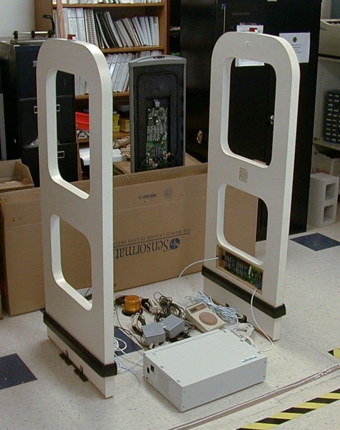
Click to zoom
Application Details
- Equipment Class
- FAP - Part 15 Anti-Pilferage Device
- Date of Grant
- Jun 22, 2000
- Application Purpose
- Original Equipment
- Date of Application
- Jun 11, 2000
- Equipment Note
- Ultra Max Advanced Digital System
- Frequency Range
- 0.05800000 - 0.05800000
- Country
- United States
Documents & Files
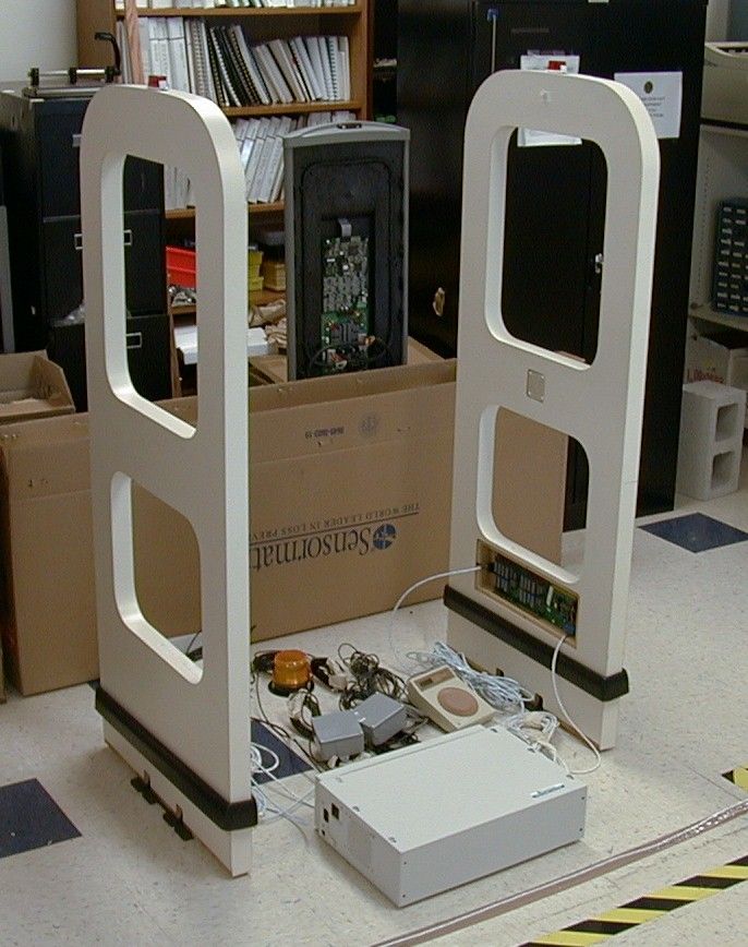
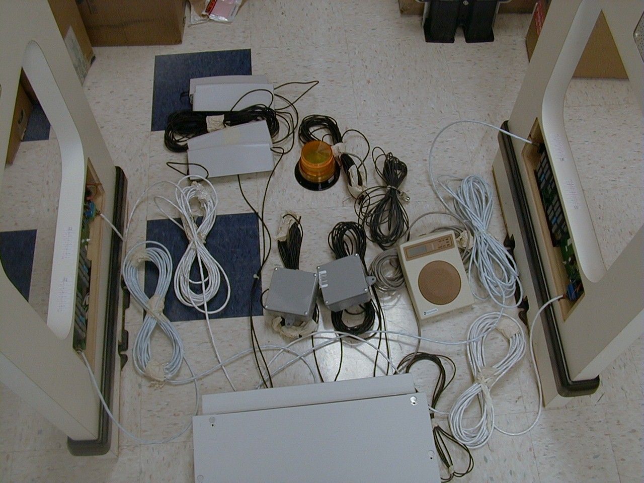
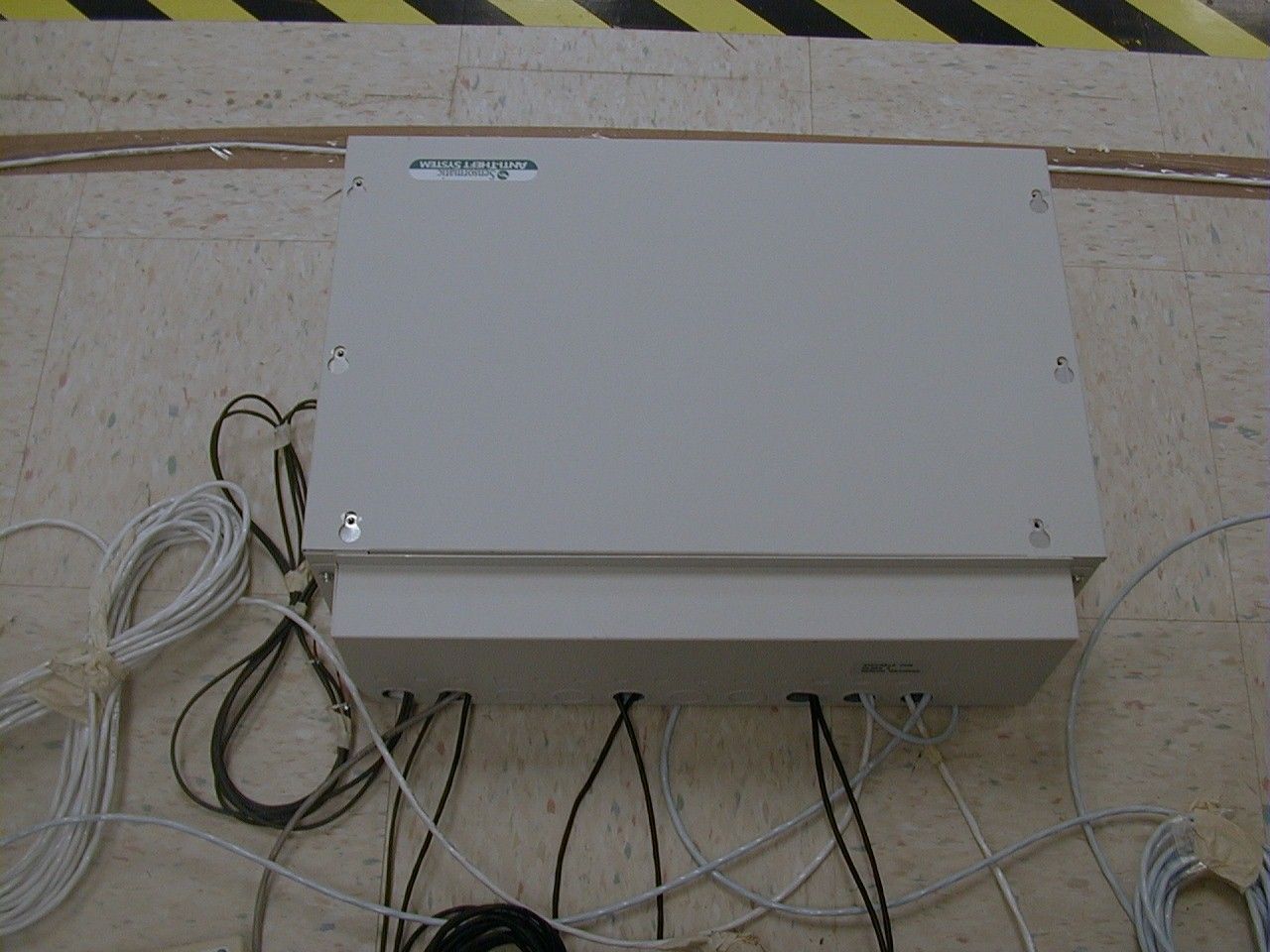
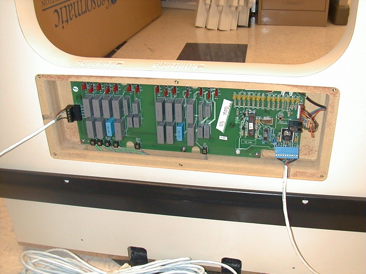
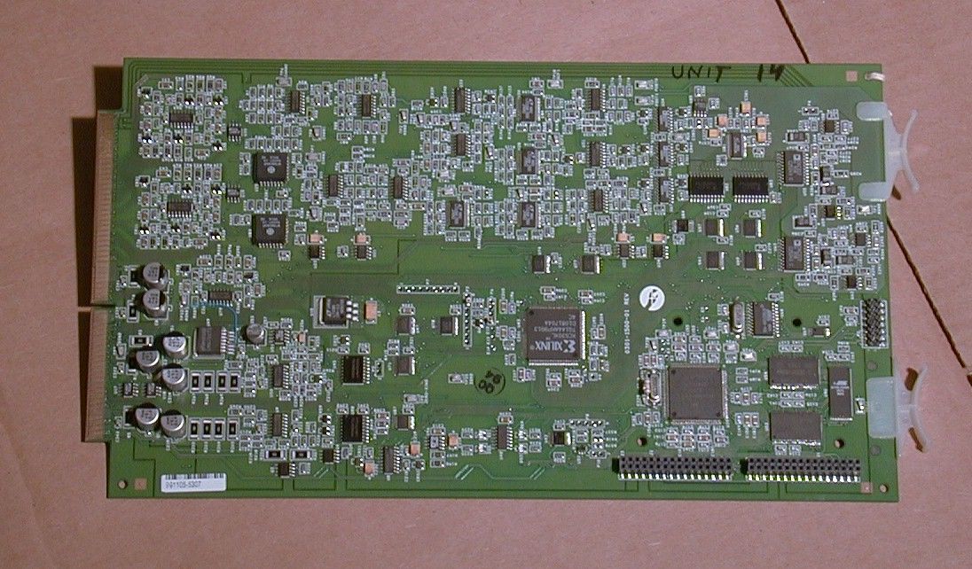
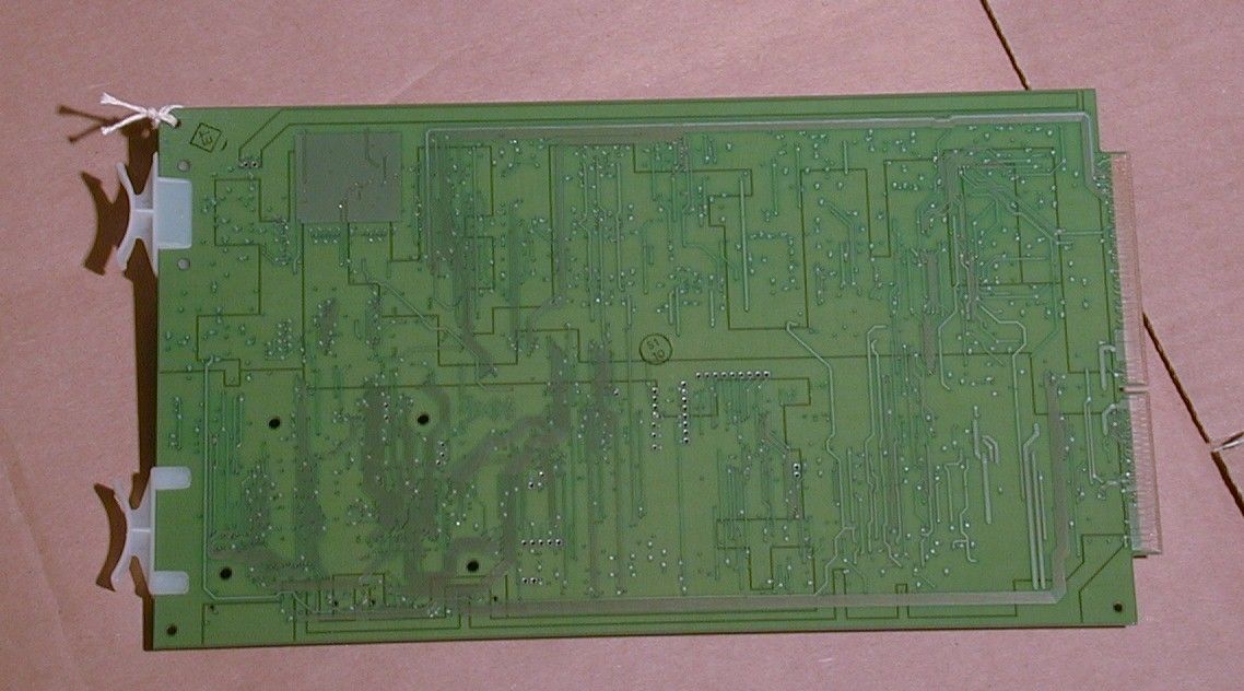
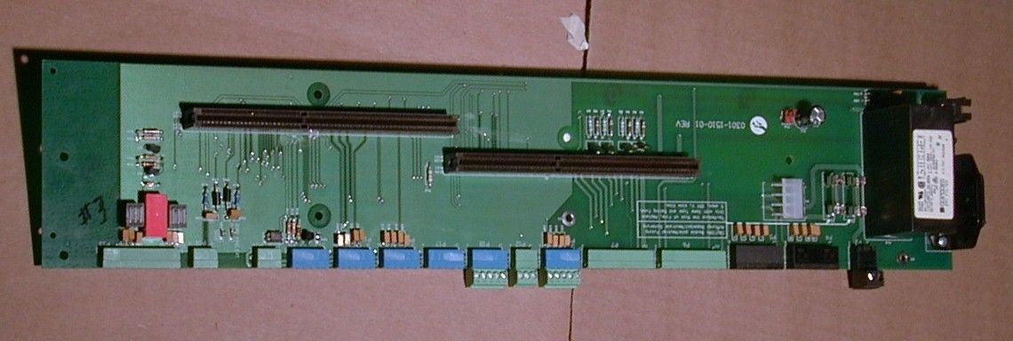
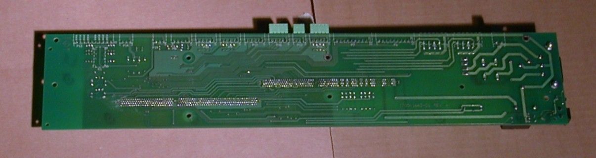
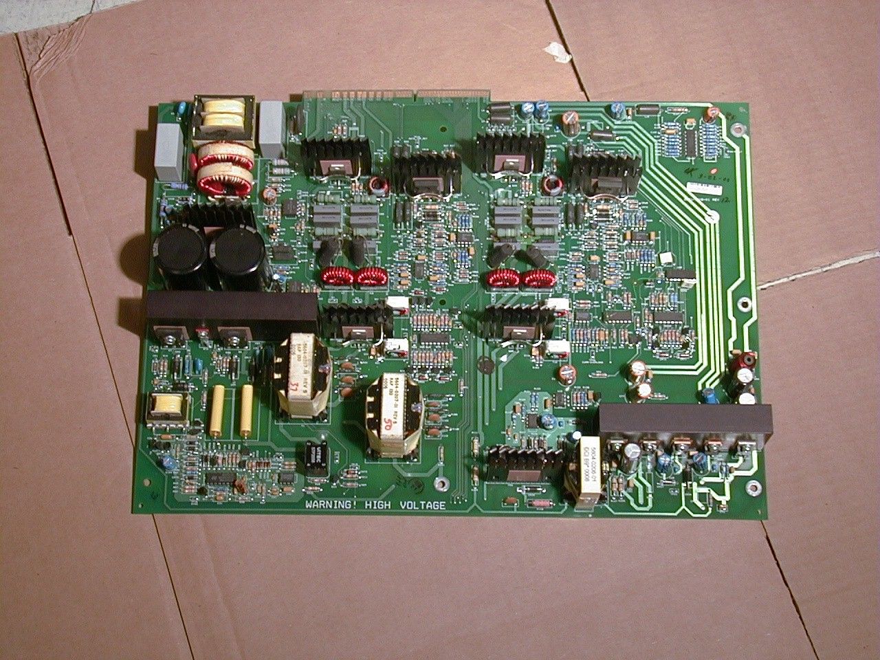
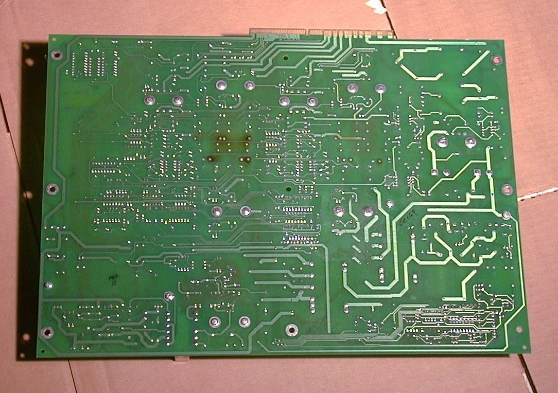
Document Text
Text extracted from the exhibit documents filed with the FCC. Open a document above to read the original.
Users Manual
WORLD LEADER IN ELECTRONIC SECURI TY Installation Guide 8000-2693-02, Rev. A (8 pages) ULTRA•MAX PRODUCTS1 1 ADS 216 Power Pack Contents About this Guide................................................ 1 Limitation of Warranty........................................ 1 Power Pack Overview........................................ 2 Installation Requirements................................... 2 Installing the Power Pack................................... 3 Connecting the Alarm Cable............................... 4 Connecting Power to the Power Pack................. 5 Specifications.................................................... 7 Declarations...................................................... 8 About this Guide This installation guide explains how to install the ADS 216 Power Pack. Other related documents are: • Planning Guide, 8000-2693-01 • Installation G uide, ADS Pro•Max Pedestals, 8000-2693-03 • Installation Guide, ADS Floor•Max Antennas, 8000-2693-03 • Setup and Service Guide, 8000-2693-xx • Reference Guide, 8000-2693-xx Note: Because placement of system components depends on architectural and customer require- ments, your Sensormatic representative will supply this information separately. If you need assistance... Call Sensormatic Customer Support at: 1-800-543-9740 Limitation of Warranty Any deviations from the materials or procedures specified herein shall void Sensor matic's warranty with the owner/buyer. In no event shall Sensor- matic be liable for loss or damage caused by the use of materials or procedures that do not meet Sensormatic's specifications. Ultra•Max, Sensormatic, and the Sensormatic logo are registered trademarks of Sensormatic Electronics Corporation. Other product names (if any) mentioned herein may be trademarks or registered trademarks of other companies. No part of this guide may be reproduced in any form without written permission from Sensormatic Electronics Corporation. © Copyright 2000. All rights reserved. DOJ 01/00 PRELIMINARY – 01/05/00 2INSTALLATION GUIDE ADS 216 POWER PACK 8000-2693-02, REV. A Power Pack Overview The ADS 216 Power Pack is part of an Ultra•Max security label detector. The power pack controls up to two transceiver antennas and two remote alarms. Figure 1. Ultra•Max Detector The ADS 216 Power Pack, ZEADS216 (Non- European) ships with the antennas or can be ordered separately. Installation Requirements Verifying Equipment and Unpacking ❑ Verify that all equipment has arrived. Make sure the system configuration is the right one for the installation site. ❑ Unpack major components in a back room. At the install site, lay out parts in the order you will need them. Do not clutter the aisle or cause a trip hazard. Installer/Contractor ❑ Shall have electrical work comply with the latest national electrical code, national fire code, and all applicable local codes and ordinances. ❑ Shall coordinate all work with other trades to avoid interference. ❑ Shall verify existing site conditions and coordinate with the owner’s representative and appropriate utilities as required. ❑ Shall obtain copies of all related plans, specifications, shop drawings and addenda to schedule and coordinate related work. ❑ Shall thoroughly review the project to ensure that all work meets or exceeds the above requirements. Any alleged discrepancies shall be brought to the attention of Sensormatic Electronics. ! WARNING! Do not install this product in hazardous areas where highly combustible or explosive products are stored or used. Electrical Requirements ❑ Connect the pack to a 100-120Vac or 220- 240Vac source. No fuse exchange is required for the power pack. ❑ The ac source must be unswitched with less than 0.5Vac between neutral and ground. ❑ DO NOT share the ac source with neon signs, motors, computers, cash registers, terminals, or data communications equipment. ❑ DO NOT use orange-colored outlets dedicated for computer equipment. Power pack Optional remote alarm Antennas ADS 216 POWER PACK 8000-2693-02, Rev. A INSTALLATION GUIDE3 Power Pack ❑ The pack can be placed on a shelf or mounted on a wall. The pack can be hidden in a remote location such as checkout counter, back room, or basement. ❑ Provide a minimum of 20cm (8") of unobstructed space around the pack for ve nti latio n. ❑ Use the appropriate power cord based on the country of use. USA-IEC 320, 18/3, 125V, 10A, 7.5ft.0351-0547-01 Schuko-IEC 320, 1mm sq., 250V, 10A, 2.5m0351-0547-02 UK-IEC 320, 1mm sq., 250V, 10A, 2.5m0351-0547-03 Japan-IEC 320, 2mm sq., 250V, 15A, 2.5m0351-0547-04 US-Filter, Line, 125V, 6A, Plug-in0351-0547-05 Australia to IEC 320, 2.5m, 250V, 10A0351-0547-07 ❑ Replace the pack’s slow-blow fuses only with a fuse of the same type and rating. ❑ Maximum cable distance from the antennas to the power pack is 12.2m (40'). ZC30-XP/ZC35-XP Remote Alarm Unit (if used) ❑ Plug the transformer used to power the alarm into a 24-hour, unswitched outlet. ❑ Maximum cable distance from the power pack to each alarm unit is about 7.6m (25'). Tools and Equipment Required For all system installations: • 6 mil (minimum) plastic sheeting (to protect nearby items from dust) • Permanent marker and/or pencil • Hammer drill with 6.5mm (1/4") and 9.6mm (3/8") masonry drill bits • Power drill with 1.6mm (1/16"), 6.5mm (1/4"), and 9.6mm (3/8") drill bits • Hammer • Phillips and slotted screwdrivers • Ratchet and socket set • Vacuum and broom Installing the Power Pack The pack can rest on a shelf (no mounting procedure required) or can be hung on a wall. To mount the pack on a wall, proceed to the section “Wall-mounting the Power Pack” on page 3 . Otherwise, go to “Connecting the Alarm Cable” on page 4 . Wall-mounting the Power Pack 1. Attach the bracket to the wall (Figure 2). The pack can be mounted on studs using screws or on wall-board using screws and anchors. a. Position wall-mount bracket and level it to mark the mounting hole locations. Remove the bracket. b. If mounting on wall-board, drill four holes fo…
Text truncated - open the document above for the full version.
Users Manual
WORLD LEADER IN ELECTRONIC SECURI TY Installation Guide 8000-2693-03, Rev. A (10 pages) ULTRA•MAX PRODUCTS1 1 ADS Pro•Max Pedestals (Alpha I Version) Contents About this Guide................................................ 1 Limitation of Warranty........................................ 1 Pedestal Overview............................................ 2 Component Part Numbers ................................. 2 Installation Requirements................................... 4 Installing ADS Pro•Max Pedestals...................... 5 Specifications.................................................... 9 Declarations.................................................... 10 About this Guide This installation guide explains how to install ADS Pro•Max ™ pedestals. Other related documents are: • Planning Guide, 8000-2693-01 • Installation Guide, ADS 216 Power Pack, 8000- 2693-02 • Setup and Service Guide, 8000-2693-xx • Reference Guide, 8000-2693-xx Note: Because the placement of antenna components can vary depending on architectural and customer requirements, your Sensormatic representative will supply t his information separately. If you need assistance... Call Sensormatic Customer Support at: 1-800-543-9740 Limitation of Warranty Any deviations from the materials or procedures specified herein shall void Sensor matic’s warranty with the owner/buyer. In no event shall Sensor- matic be liable for loss or damage caused by the use of materials or procedures that do not meet Sensormatic’s specifications. Ultra•Max, Sensormatic, and the Sensormatic logo are registered trademarks and Pro•Max is a trademark of Sensormatic Electronics Corporation. Other product names (if any) mentioned herein may be trademarks or registered trademarks of other companies. No part of this guide may be reproduced in any form without written permission from Sensormatic Electronics Corporation. © Copyright 2000. All rights reserved. DOJ 01/00 PRELIMINARY 01/05/00 2INSTALLATION GUIDE ADS PRO•MAX PEDESTALS 8000-2693-03, REV. A Pedestal Overview ADS Pro•Max pedestals are part of an Ultra • Max ® security label detector that deters theft. One or two ADS Pro•Max pedestals are attached to a power pack. Pedestals are positioned opposite each other at an exit. CAUTION: Space pedestals no more than 2.4m (9') apart. Figure 1. ADS Pro•Max Detector Component Part Numbers ADS Pro•Max Pedestal System, Single – xxxxxxxx − One ADS Pro•Max Pedestal (0300-2302-01) − One Power Pack (ZEADS216) − One Power Cord Option (0351-0547-xx) ADS Pro•Max Pedestal System, Dual – xxxxxxxx − Two ADS Pro•Max Pedestals (0300-2302-01) − One Power Pack (ZEADS216) − One Power Cord Option (0351-0547-xx) Power pack Optional remote alarm Pedestals ADS PRO•MAX PEDESTALS 8000-2693-03, Rev. A INSTALLATION GUIDE3 Figure 2. Wiring diagram Com Cable 0650-2220-01 (9 conductor) P4 Tx/Rx Ped. A P6 Com Ped. A P5 Tx/Rx Ped. B P7 Com Ped. B P13 Relay A-B P11 Ferrite P12 Option 3 P18 Option 2 P17 Option 1 P9 Noise Coil A P10 Noise Coil B P14 RS485 P8 ADS Alarm ADS Power Pack BLKREDGRNWHTSHLD Tx/Rx 1 2 3 4 5 Com 1 2 3 4 5 6 7 8 9 10 BLKBRNREDORGYELGRNBLUVIOGRYSHLD Pedestal A BLKREDGRNWHTSHLD P1 1 2 3 4 5 P6 1 2 3 4 5 6 7 8 9 10 BLKBRNREDORGYELGRNBLUVIOGRYSHLD Pedestal B Tx/Rx Cable 0650-2219-01 (4 conductor) Com Cable 0650-2220-01 (9 conductor) Tx/Rx Cable 0650-2219-01 (4 conductor) P6 P1 P6 P1 4INSTALLATION GUIDE ADS PRO•MAX PEDESTALS 8000-2693-03, REV. A Installation Requirements Verifying Equipment and Unpacking ❑ Verify that all equipment has arrived. Make sure the system configuration is the right one for the installation site. ❑ Unpack major components in a back room. At the install site, lay out parts in the order you will need them. Do not clutter the aisle or cause a trip hazard. Installer/Contractor ❑ Shall have electrical work comply with the latest national electrical code, national fire code, and all applicable local codes and ordinances. ❑ Shall coordinate all work with other trades to avoid interference. ❑ Shall verify existing site conditions and coordinate with the owner’s representative and appropriate utilities as required. ❑ Shall obtain copies of all related plans, specifications, shop drawings and addenda to schedule and coordinate related work. ❑ Shall thoroughly review the project to ensure that all work meets or exceeds the above requirements. Any alleged discrepancies shall be brought to the attention of Sensormatic Electronics. ! WARNING! Do not install this product in hazardous areas where highly combustible or explosive products are stored or used. Antenna Placement and Cabling ❑ Whenever possible, keep the pedestals at least 2.4m (8') away from noise sources such as computer monitors, TV’s, switching power supplies, and neon displays. ❑ Do not position pedestals more than 2.7m (9') apart. ❑ Maximum cable distance from the pedestals to the power pack is 12.2m (40'). Tools and Equipment Required For all ADS Pro•Max installations: • 6 mil (minimum) plastic sheeting (to protect nearby items from dust) • Permanent marker and/or pencil • Floor saw • Hammer drill with 6.5mm (1/4") and 9.6mm (3/8") masonry drill bits • Power drill with 1.6mm (1/16"), 6.5mm (1/4"), and 9.6mm (3/8") drill bits • Hammer • Phillips and slotted screwdrivers • 14-16 AWG and 16-22 AWG wire strippers • 2.4mm (.093") Molex extractor tool • Ratchet and socket set • Hand vacuum and broom ADS PRO•MAX PEDESTALS 8000-2693-03, Rev. A INSTALLATION GUIDE5 Installing ADS Pro•Max Pedestals 1. Position ADS Pro•Max pedestals at exact mounting location (Figure 3). DO NOT space pedestals more than 2.7m (9') apart. Figure 3. Pedestal spacing 2. If you need to trench the floor between the pedestals, do the following: Using the floor saw and the appropriate blade, trench the floor from pedestal to pedestal. Trench depth is 1.5cm (3/4"); trench width is .5cm (1/4"). Trench depth allows for .5cm (1/4") of floor compound above the cable. Make sure that the trench extends under the pedestal location so cables…
Text truncated - open the document above for the full version.
Users Manual
WORLD LEADER IN ELECTRONIC SECURI TY Installation Guide 8000-2693-04, Rev. A (19 pages) ULTRA•MAX PRODUCTS1 1 ADS Floor•Max Antennas Contents About this Guide................................................ 1 Limitation of Warranty........................................ 1 Antenna Overview............................................. 2 Installation Requirements................................... 3 Installing ADS Floor•Max Antennas.................... 7 Connecting Conduit and Cables....................... 11 Antenna Tuning............................................... 15 Pouring the Concrete....................................... 16 Specifications.................................................. 18 Declarations.................................................... 19 About this Guide This installation guide explains how to install ADS Floor•Max antennas. Other related documents are: • Planning Guide, 8000-2693-01 • Installation G uide, ADS 216 Power Pack, 8000-2693-02 • Setup and Service Guide, 8000-2693-xx • Reference Guide, 8000-2693-xx Note: Because placement of antenna components depends on architectural and customer require- ments, your Sensormatic representative will supply this information separately. If you need assistance... Call Sensormatic Customer Support at: 1-800-543-9740 Limitation of Warranty Any deviations from the materials or procedures specified herein shall void Sensor matic's warranty with the owner/buyer. In no event shall Sensor- matic be liable for loss or damage caused by the use of materials or procedures that do not meet Sensormatic's specifications. Ultra•Max, Floor•Max, Sensormatic, and the Sensormatic logo are registered trademarks of Sensormatic Electronics Corporation. Other product names (if any) mentioned herein may be trademarks or registered trademarks of other companies. No part of this guide may be reproduced in any form without written permission from Sensormatic Electronics Corporation. © Copyright 2000. All rights reserved. DOJ 01/00 PRELIMINARY – 01/31/00 2INSTALLATION GUIDE AD S FL O OR • M A X AN TE N N AS 8000-2693-04, REV. A Antenna Overview ADS Floor•Max antennas, positioned at an exit, are part of an Ultra•Max security label detector that deters theft. One or two ADS Floor•Max in-floor antennas are attached to a power pack through a capacitor board enclosure. Figure 1. ADS Floor•Max Detector Component Part Numbers ADS Floor•Max 6' System − 1 ADS Floor•Max Antenna (ZSFLORMX- ANT) − ADS Enclosure Assembly (ZPFLORMX- ENC) − RS232 Assembly (ZPFLORMX-232) − ADS Power Pack (ZEADS216) ADS Floor•Max 12' System − 2 ADS Floor•Max Antennas (ZSFLORMX- ANT) − ADS Enclosure Assembly (ZPFLORMX- ENC) − RS232 Assembly (ZPFLORMX-232) − ADS Power Pack (ZEADS216) ADS Floor•Max Antenna (ZSFLORMX-ANT) − Install kit (0351-1696-01) − Capacitor board (0301-1536-01) − Antenna (0300-2289-01) ADS Floor•Max Shield (ZPFLORMX-SH) − Shield tray - left (0300-9219-01 − Shield tray - right (0300-9219-02) − Shield tiles (0500-9216-01) Power pack Optional remote alarm In-floor antennas Cap board enclosure RS232 plate AD S FL O OR • M A X AN TE N N AS 8000-2693-04, Rev. A INSTALLATION GUIDE3 Installation Requirements Verifying Equipment and Unpacking ❑ Verify that all equipment has arrived. Make sure the system configuration is the right one for the installation site. ❑ Unpack major components in a back room. At the install site, lay out parts in the order you will need them. Do not clutter the aisle or cause a trip hazard. Note: The capacitor board is in a cardboard sleeve taped to the bottom of the antenna shipping box. The PVC leveling legs are inside one of the cardboard support ribs on the end of the box. Installer/Contractor ❑ Shall have electrical work comply with the latest national electrical code, national fire code, and all applicable local codes and ordinances. ❑ Shall coordinate all work with other trades to avoid interference. ❑ Shall verify existing site conditions and coordinate with the owner’s representative and appropriate utilities as required. ❑ Shall obtain copies of all related plans, specifications, shop drawings and addenda to schedule and coordinate related work. ❑ Shall thoroughly review the project to ensure that all work meets or exceeds the above requirements. Any alleged discrepancies shall be brought to the attention of Sensormatic Electronics. Chemical Interaction ! WARNING! Do not install this product in hazardous areas where highly combustible or explosive products are stored or used. Antenna Placement and Cabling ❑ Whenever possible, keep the antennas at least 2.4m (8') away from noise sources such as computer monitors, TV’s, switching power supplies, and neon displays. ❑ Maximum cable distance from the antennas to the capacitor board enclosure is 12.2m (40'). DO NOT splice antenna cables. ❑ Maximum cable distance from the power pack to the cap board enclosure is 2m (7'). ! WARNING! DO NOT compromise the structural integrity of the floor by cutting or removing rebar. Contractors must obtain approval for all proposed structural changes. All structural changes must meet national and local requirements. CAUTION: To avoid adding significant time and cost to the in-floor installation, check detector per- formance and label detection height at the exact installation site. Do this BEFORE cutting the floor and again BEFORE pouring the concrete. ❏ Locate panels inside t he facility and as close to exit doors as possible. ❏ To provide 1.8m (6') of coverage width per panel, space panels no more than 25-30cm (10-12") apart. Spacing of 25cm (10") is recommended. ❏ For On Grade installations, the panels must be between 3cm (1.25") and 5cm (2") below the surface of the finished floor. ❏ For Off Grade installation, the panels must be 1.25cm (.5") below the surface of the finished floor. ❏ For On Grade installations, no metal such as rebar or wire mesh should be located under or adjacent to the antenna. If metal is required, it must be spaced greater than 2…
Text truncated - open the document above for the full version.
Block Diagram
Power Supply/Transmitter Board I/O Option Port B a c k p l a n e AC input IEC or Hard wire Tx Outputs Alarm/RS232 Remote Alarm Noise Canselation Ferrite Rx 60 Hz Sync RS485 ADS216 Power Pack Block Diagram I/O Option Port Signals AC Switch RS 232 Power on LED 12VDC FAN Receiver/DSP Board Analog Front End Crosspoint Switch Mux A/ D SCF Clock (1.45MHz) FPGA A/D Clock (909090 Hz) Alarm Driver Pedestal Comm Buffer 2F0 (116KHz) DSP FPGA Clock (80 Mhz) 20.0 MHz Crystal Atmel Controller 3.6864 MHz Crystal NVM RS485 Power Sync Clock 2F0 (116KHz) P ow er Amplif ier 57.8 / 58.2 KHz Logic Supply 96 KHz RC Control
ID Label/Location Info
THIS DRAWING MAY CONTAIN PATENTED OR PROPRIETARY INFORMATION AND MUST NOT BE USED FOR MANUFACTUR- ING OR ANY PURPOSE DETRI- MENTAL TO SENSORMATIC ELECTRONICS. ACCEPTANCE OF THIS DRAWING WILL BE CONSTRUED AS AN AGREE- MENT TO AND ACCEPTANCE OF THE FOREGOING. DECIMALS X. X = +/ - . 5 mm X. XX = +/ - . 3 mm X. XXX = +/ - . 1 mm FINISH N/A ANGLES +/- 1/2 DEGREE RELEASE APP’D CHECKED DRAWN R. CERASINI APPROVALS DIMENSIONS ARE SHOWN IN MILLIMETERS DATE 5-23-94 SENSORMATIC ELECTRONICS CORP. DEERFIELD BEACH, FLORIDA SIZE A DRAWING NUMBER 2402-0469-00 TITLE LABEL,UNIVERSAL REV BV SHEET 2 OF 73 ENGR TOLERANCES ARE: MATERIAL 1 Sensormatic THE WORLD LEADER IN LOSS PREVENTION TECHNOLOGY 1.54 MIN 4 x V ~ VOLTAGE SYMBOL PRINT SYMBOL AS SHOWN NOTES: 1 MATERIAL: MAKE FROM 2402-0357-08. (SEE B/M) 2. FIELD VARIABLES ARE SHOWN AS HEXAGONS. SEE ATTACHED LISTING FOR DESCRIPTIONS. 12 1 2 3 4 5 67 13 8 11 10 9 Figure A Figure B Figure C Figure D Figure E Figure F LISTED 441X LISTED 5F48 C ANTITHEFT DEVICES, AND HOSPITAL SIGNALLING ACCESSORY EQUIP. AND MISC. SIGNALLING DEVICE MISC. SIGNALLING DEVICE INFORMATION TECHNOLOGY EQUIPMENT INFORMATION TECHNOLOGY EQUIPMENT E.D.P. EQUIPMENT REV BV SHEET 3 OF 73 SCALE: NO NE DRAWING NUMBER 2402-0469-00 SIZE A C U L U L U L C U L U L PART NO.NO.DESCRIPTION 2402-0469-71PRINT THE FOLLOWING FIELD INFORMATION PRODUCT CODES1ZEADS216 REG ID2REG ID: UM ADSDAAA PART NUMBER3P/N: 0309-0069-01 REV (CURRENT) SERIAL NUMBER4S/N: (CURRENT) RATING5100-120/220-240V~ 4.0/2.0A 50-60HZ (PRINT “V~” PER SHEET 2) UL LOGO6( PRINT AS SHOWN ON PAGE 3 FIG. C ) C-UL LOGO7( PRINT AS SHOWN ON PAGE 3 FIG. F ) COUNTRY OF MANUF8MADE IN (COUNTRY OF ORIGIN) (FOR COUNTRY OF ORIGIN PRODUCTION CONTROL TO INSERT COUNTRY BASED UPON M ANUFACTURI NG LO CATI O N) TUV LOGO9 FCC STATEMENT10FCC ID: BVCUMADSNE THIS DEVICE COMPLIES WITH PART 15 OF THE FCC RULES. OPERATION IS SUBJECT TO THE FOLLOWING TWO CONDITIONS: (1) THIS DEVICE MAY NOT CAUSE HARMFUL INTERFERENCE, AND (2) THIS DEVICE MUST ACCEPT ANY INTER- FERENCE RECEIVED, INCLUDING INTERFERENCE THAT MAY CAUSE UNDESIRED OPERATION. MFG BARCODE11(LOCATE AS SHOWN) S.E.C. LOGO12(LOCATE AS SHOWN) CE13(PRINT WHERE SHOWN, VERTICAL DIMENSION AT LEAST 5 mm) NOTES/COMMENTSVARIABLES ARE DEFINED IN THE “DESCRIPTION” COLUMN. ITEMS LISTED IN PARENTHESIS ARE NOT VARIABLES, BUT DEFINE THE VARIABLE FOR THE RESPECTIVE LINE ITEM. DOMESTIC/INTERNATIONAL VERSION LABEL PART NO. 2402-0469-71REVBP
ID Label/Location Info
Label
Operational Description
ADS216 Power Pack Theory of Operation Preliminary Overview The ADS Power Pack 216 self-contained electronics is capable of driving two ADS pedestals to generate the magnetic field to excite tags as well as receive and alarm on any tag signal detected. There are three major PC boards referred to as the Receiver / DSP board, the Power Supply / Transmitter board and the Backplane. The Receiver/DSP and the Power Supply/Transmitter boards are mated together via the Backplane. All the connections to the outside are made via the Backplane. The Power Pack drives up to two pedestals, one external alarm, two noise canceling antenna used to cancel the environmental noise seen by the system. The two pedestals each contain integrated audio and visual alarm circuits. The Power Pack will accept two cancellation coils used to receive localized noise / interference sources such as ballast or motor noise. Two ferrite antennas can be included to enhance system performance. The I/O Options Port of the Power Pack will be used for future expansion if necessary. The 485 Port allows the provision for a wired network. When a tag is place in the pedestal field, an alarm indication will be initiated. This may be the integral alarm, external alarm or both.
Schematics
ZERO_XING ANTB_BOT_RET 5VREF ANTA_BOT_RET DGND E12HOLE IOUT_TOP_A +5VF IOUT_TOP_B SWITCHED_LINE ANTB_BOT +5VF 5VREF NOTE: IOUT_BOT_B TX_AMP_TYPE P1BCON242PM_CE B1B2B3B4B5B6B7B8B9 B10B11B12B13B14B15B16B17B18B19B20B21B22B23B24B25B26B27B28B29B30B31B32B33B34B35B36B37B38B39B40B41B42B43B44B45B46B47B48B49B50B51B52B53B54B55B56B57B58B59B60B61B62B63B64B65B66B67B68B69B70B71B72B73B74B75B76B77B78B79B80B81B82B83B84B85B86B87B88B89B90B91B92B93B94B95B96B97B98B99 B100B101B102B103B104B105B106B107B108B109B110B111B112B113B114B115B116B117B118B119B120B121 ANTB_BOT WIN~ V12U ANT-B-DRV4XMITTER2 TX 2FTX ANTBTOP ANTB_TOP_RET ANTBBOT ANTB_BOT_RET V12UAID FIG8 IOUT_TOP_BIOUT_BOT_B PWMOUTB PWM_OUTB +5VF +12VBIAS -12VBIAS WIN~XFMR_HVXFMR_LV +5VF IOUT_TOP_A ANTA_BOT V12U TXSIG-TOP XFMR_LV IOUT_BOT_B +12VBIAS E14HOLE ANTB_TOP_RET ANTA_BOT_RET BIAS'/TX_WIN IOUT_TOP_B P1A CON242PM_CE A1A2A3A4A5A6A7A8A9A10A11A12A13A14A15A16A17A18A19A20A21A22A23A24A25A26A27A28A29A30A31A32A33A34A35A36A37A38A39A40A41A42A43A44A45A46A47A48A49A50A51A52A53A54A55A56A57A58A59A60A61A62A63A64A65A66A67A68A69A70A71A72A73A74A75A76A77A78A79A80A81A82A83A84A85A86A87A88A89A90A91A92A93A94A95A96A97A98A99A100A101A102A103A104A105A106A107A108A109A110A111A112A113A114A115A116A117A118A119A120A121 PWM_OUTB E11HOLE E15HOLE R170 VOUT_BOT_A +12VBIAS ANTBTOP SWITCHED_NEUTRAL ANTB_TOP_RET FAN VOUT_BOT_A TX_MODEFAN-FAULT P11 TX_AMP_TYPE TRANSMITTER3XMITTER 325V2F0 TX_MODE ANTA_TOP_RET TX 2FTX TX_SW~ ANTABOT ANTA_BOT_RET V12U ANTATOP +12VBIAS -12VBIASTXSIG-TOP TX_SW~ FAN-FAULT AID FIG8 PWMOUTB AMP-TEMP-FAULTCURR-OVERLOAD IOUT_TOP_AIOUT_BOT_A 5VREF WIN~ XFMR_HV XFMR_LV BIAS'/TX_WIN ZERO_XING TX_SW~ E10HOLE ANTBBOT DGNDAMP-TEMP-FAULT ANTA_BOT FIG8 Note: TX 12V_ALARM_RET TX_SW~ -12VBIAS U12 +12V ANTB_TOP ANTA_TOP E13HOLE S0301-1508-01 3C SCHEMATIC, ADS216 XMTR/PWR SUPPLY NE C 16 Tuesday, February 22, 2000 A REL PER ER XXX (PCN#) XXX (DATE) (NAME)(NAME)(NAME)(NAME)(NAME) (DATE)(DATE)(DATE)(DATE)(DATE) 951 YAMATO ROADBOCA RATON, FLORIDA 33431 TitleSize Document Number Rev Date: Sheet of APPD BY DATE DESCRIPTION PCN NO. LTR DrawnCheckedEngrAppdRelease DATE APPROVALS Sensormatic Electronics Corp. XFMR_LV Q48 EARTH DGND PROTECTION CIRCUITS6PROT_CIR IOUT_TOP_A IOUT_BOT_A IOUT_TOP_BIOUT_BOT_B CURR-OVERLOAD FAN-FAULT FAN 12V_ALARM_RET AMP-TEMP-FAULT 12V_ALARM+5VTEMP+5VF 325V AMP-TEMP-FAULT HIGHEST REF DES. USED VOUT_TOP_A AID ANTA_TOP_RET XFMR_HV 12V_ALARM_RET IOUT_BOT_A PRIMARY AC POWER ANTBTOP +5VF ANTATOP FAN-FAULT AID DGND 12V_ALARM IOUT_TOP_B FAN ANTABOT -12VBIAS +5VTEMP PWMOUTB DGND ANT-SEL-A FIG8 +5VF VOUT_BOT_B * THIS SIGNAL USED ON THE LPA BOARD AC INPUT/LOGIC SUPPLY2LVPS SWITCHED_LINE SWITCHED_NEUTRAL ZERO_XING 325V -12V +12V +12VBIAS -12VBIAS 12V_ALARM_RET 12V_ALARM +5VTEMP +5VF 5VREF ANTA_TOP -12VBIAS DO NOT INSERT CR 79-86 VOUT_TOP_A IOUT_BOT_A 12V_ALARM DGNDDGND IOUT_TOP_A TX 2FTX DGND TX_MODE CURR-OVERLOAD +12V VOUT_TOP_B TXSIG-TOP ANT-SEL-B PWMOUTB C107 EARTH SWITCHED_NEUTRAL VOUT_BOT_B Need to be Added tothe BOM on AMAP 50V. +/-5%, 1/4W. Notes: 1. UNLESS OTHERWISE SPECIFIED: ALL RESISTOR VALUES ARE IN OHMS RESISTOR POWER RATINGS ARE CAPACITOR VALUES ARE IN MICRO FARADS, CURR-OVERLOAD VOUT_TOP_B XFMR_HV IOUT_BOT_A J7 ANT-SEL-B OUTPUT SEQUENCER/TUNING5SEQUENCER VOUT_TOP_BVOUT_BOT_B VOUT_TOP_AVOUT_BOT_A ANTATOPANTABOT ANTBTOP ANTBBOTANT-SEL-AANT-SEL-BV12U 5VREFTX 2FTX ANTA_TOP ANTA_BOTANTB_TOP ANTB_BOT -12VBIAS +12VBIAS ANTA_TOP_RET ANTA_BOT_RETANTB_TOP_RETANTB_BOT_RET ANTBBOT -12V TX_SW~ 12V_ALARM_RET FAN-FAULT +5VTEMP IOUT_BOT_B TX_SELA_BOT* SWITCHED_LINE CURR-OVERLOAD R2410 2FTX AMP-TEMP-FAULT WIN~ ANTA_TOP_RET PWM_OUTB -12V +12VBIAS ANTB_BOT_RET 2F0 R8910K ANT-SEL-A J2CON, HDR 1 2 CR40 12V_ALARM ANTB_TOP 2F0 R910
Schematics
R9610K1W5% CR76 751A5.1V 12 VFB CR37RECVRY 1 2 + C771000UF10V + C139 33UF25V HOT R10018.2K C71 .1UF R1284.99K C55 100P 5% + C52 2200UF200VDC U7 AVS1BCP08 12 76 543 8 VssOsc/In Mode NC VGVddOsc/Out Vm R1255.23K R255 33 .5W R92 360K .5W R115 16.9K CR42150 1 2 ZERO_XING C66 .1UF L6500UH 1 2 12V_ALARM_RET NEUT U13LT1085CT 3 1 2 VI GND VO CR79 SUPPR 12 R2485K +12V C47 2200P250VAC 5VREF R1234.75K U8HCNW4502 12 87 4 65 3 R109180K.5W CR40, CR44, U9,U10, AND U13 AREATTACHED TO HS7 VFB + C68 100UF 35V + C62 100UF35V MIN +12VBIAS C83 .001UF 12VSWT U9MC7812CT 1 2 3 VI GND VO C53.1UF L434MH 8 5 1 4 C851UF NEUT C94 .1UF200V 1 TP27TEST PT, JMPR - + CR29 BRIDGE RCT 2 1 3 4 -12V R1300 ZERO_XING + C59 47UF50V CR32 5245B 12 RV2VARISTOR 12 C74 .1UF R94 1M HS7HEATSINK 12 C50 2200P250VAC G A2 A1 Q20 AVS08CB 2 13 CL-70 CR34 305 1 2 R121 4.99K CR38RECVRY 1 2 L910UH 1 2 R111180K.5W + C51 2200UF200VDC C58.01UF t RT1I LIMIT 1 2 325V NEUT CR44FST RCV 1 2 3 C81 .1UF C67 3300P1KV Zero Crossing Circuit 5VREF1 CR43 150 12 R104100K R9951K RV1VARISTOR 12 5VREF1 CR394003 1 2 1 TP31TEST PT, JMPR + C76 47UF35V MIN EMI Filter R1180 CR40745 2 1 R11910K 1 TP29TEST PT, JMPR L8 500UH 1 2 R116130 R10833K2W R112 5.1K SWITCHED_LINE T7PCMT 8 6 7109 1 1211 42 ZERO_XING C70.1UF 1 TP33 TEST PT, JMPR R97160K.5W 325V HOT +5VF C140.1UF + C891000UF 35V C75 .1UF 12V_ALARM + C61 100UF35V MIN C49 1UF250VAC +5VF R10151K 1W CR284007 12 + C801000UF10V C56 1000P CR30 4007 12 R2521.24K 1 TP30TEST PT, JMPR C84 1200P Need to changeR252 value togive 13VDC + C73 100UF35V MIN L5396UH 1800-0159-01 1 2 C64.1UF CR314148 12 SWITCHED_NEUTRAL S0301-1508-01 3C SCHEMATIC, ADS216 XMTR/PWR SUPPLY NE C 26 Tuesday, February 22, 2000 951 YAMATO ROADBOCA RATON, FLORIDA 33431 TitleSize Document Number Rev Date: Sheet of Sensormatic Electronics Corp. 12VSWT R98 191 R1200.5 C60 330P C86.001UF200V R1244.75K R103 51K 1W U10 MC79M12CT 2 1 3 VI GND VO 1 TP28 L3396UH 1800-0159-01 1 2 CR351100E 12 R95160K.5W CR41 5374 12 R122360 L7500UH 1 2 C93.1UF HS5TO218 1 2 C48 1UF250VAC R105470 U11CS3842AN 12345 678 COMPVFBISENSERT/CTGND OUT VCC VREF R126 1K 1 TP26TEST PT, JMPR CR80 SUPPR 12 + C5433UF25V U14 TL431ACLP 23 1 + C69100UF 35V NOTE: PARTS IN DASHED LINESNOT INSTALLED +5VTEMP LOGIC SUPPLY C65 .01UF100V C79 .01UF 100V R114180K1/2W 1 TP34TEST PT, JMPR + C91 1000UF 35V + C781000UF10V R10610K 325V Rectifier/Bulk Storage R10251K R251121 R249 10K C72.01UF100V -12VBIAS C88 .1UF200V C82 1000P2% R12733.5W R1171K HS6TO218 1 2 Q22MFET, N 2 1 3 Q21 NPN, 18 2 13 C141.001UF200V R113 220 1 TP32 CR33 150 12 R107 90.9K + C63 100UF 35V R9310K1W5% C87470P 1 TP23TEST PT, JMPR C92.1UF CR81SUPPR 12 U12CNY17F-1.300W 12 654 3 + C90 1000UF 35V CR82 SUPPR 12
Schematics
IOUT_BOT_A C25.1UF AMP-TEMP-FAULT CR6 460 12 R24453.6K R10 68K U24C MC74HCT08AN 9 10 8 J1CON, HDR 1 2 1TP16 TEST PT, JMPR TX Q11NPN, 2222A 2 13 + - U5BLM393AN 56 7 1 E3 R8610K 5VREF_IC CR105221 1 2 R5110K C18.01UF R651K 1 E1 S0301-1508-01 3C SCHEMATIC, ADS216 XMTR/PWR SUPPLY NE Custom 36 Thursday, March 09, 2000 951 YAMATO ROADBOCA RATON, FLORIDA 33431 TitleSize Document Number Rev Date: Sheet of Sensormatic Electronics Corp. U3ECD74HC14E 11 10 U25ACD74HC123E 1415 123 134168 CEXTREXT/CEXTABCLR QQ VCC GND CR24 4148 1 2 CURR-OVERLOAD +- U1B MB47833P 56 7 +- U5ALM393AN 32 1 84 CR25 1N5818 SHTKYDIO 12 R72.2K T4B100K 23 R70 2.2K 5VREF C6 3300P1KV Q9NPN, 2222A 2 13 Q2 MFET, 240 2 1 3 1 TP5 TEST PT, JMPR V12U CR17 150 12 Q13NPN, 2222A 2 13 WIN~ R61 2.2K R34100 HS3HEATSINK 12 5VREF R524.7K L2 4.7UH 1 2 C29 .1UF R39 68K Q41PNP, 2907A 2 31 2F0 R24150 3W Q17NPN, 2222A 2 13 2FTX R25 20 5W U3BCD74HC14E 3 4 C41 .1UF 2FTX R714.7K C14 .1UF 2FTX TX 2FTX C22 .047UF400V U3CCD74HC14E 5 6 T1AVT 91 R671K HS1TO218 12 R6820K T2CPC 109 Q1 & Q8 mountedto H1 R41 2.4K .5W U2SG3525AN 4 216 12 14161110 9 15 813 753 OSC N.I.INVRTGND OUT B VREF OUT A SDWN COMP+VIN SS VC DISCTSYNC R4710K T1C VT 1410 CR23 4148 1 2 +12VBIAS PWMOUTB R254 0 CR75 1N5818 SHTKYDIO 1 2 R661K CR15 5221 12 R5312.7K C3.01UF CR74 1N5818 SHT…
Text truncated - open the document above for the full version.
Contact Information
Applicant
Mark D. Alexis(Manager Regulatory Compliance)
Technical Specifications
| # | Rule Parts | Frequency Range | Power Output |
|---|---|---|---|
| 1 | 15C | 0.058 MHz - 0.058 MHz | - |
Other Applications from Tyco Safety Products/Sensormatic

BVCIDX5000
Jun 23, 2026UHF RFID Reader
Equipment Class
DSS - Part 15 Spread Spectrum TransmitterBVCAMS1137H
Dec 22, 2025Anti Theft System - Electronic Asset Security
Equipment Class
FAP - Part 15 Anti-Pilferage DeviceBVCAMB9012
Sep 10, 2024Label Deactivator Controller
Equipment Class
DCD - Part 15 Low Power Transmitter Below 1705 kHz
BVC-4000-PI26
Sep 24, 2015RM2L-4000-P126, RM2-4000-P126
Equipment Class
DXX - Part 15 Low Power Communication Device Transmitter
BVCAMS90604
May 20, 2014Anti-pilferage Device
Equipment Class
FAP - Part 15 Anti-Pilferage Device