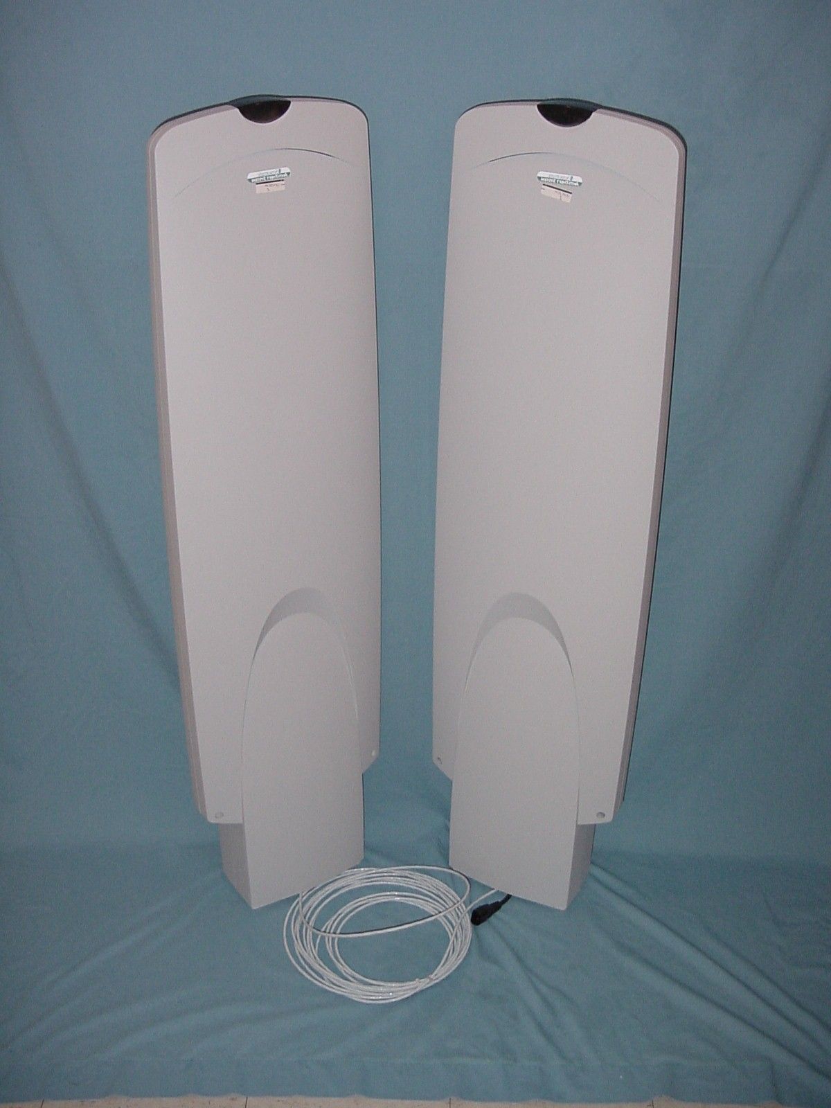
BVCUMEMAX2Anti-Pilferage Device
Tyco Safety Products/Sensormatic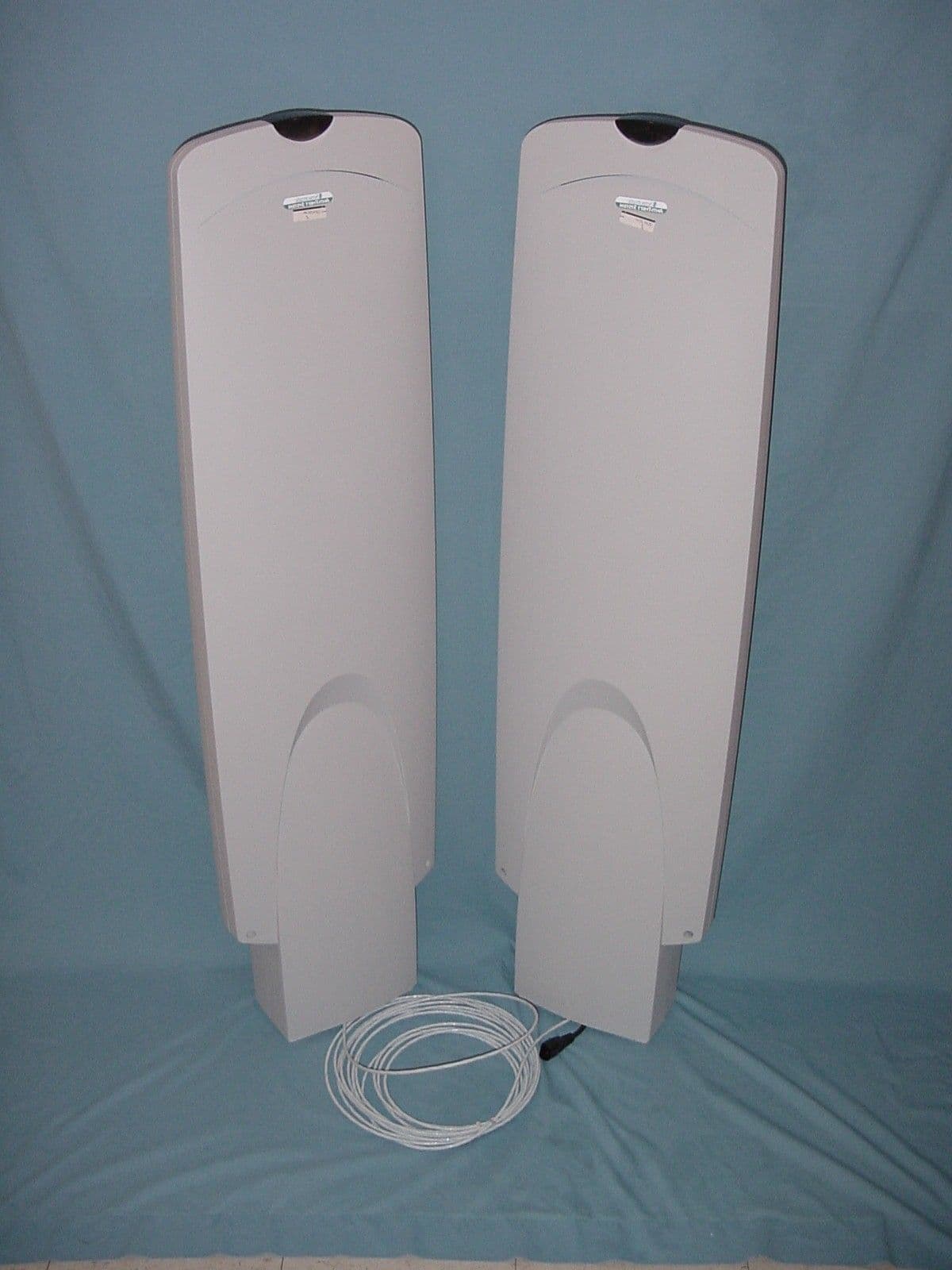
Click to zoom
Application Details
- Equipment Class
- FAP - Part 15 Anti-Pilferage Device
- Date of Grant
- Jan 03, 2002
- Application Purpose
- Original Equipment
- Date of Application
- Jan 03, 2002
- Equipment Note
- Anti-Pilferage Device
- Frequency Range
- 0.05780000 - 0.05820000
- Country
- United States
Documents & Files
Document Text
Text extracted from the exhibit documents filed with the FCC. Open a document above to read the original.
Users Manual
Company Confidential-Preliminary E-MAX EAS DETECTOR INSTALLATION AND TROUBLESHOOTING GUIDE (8000-2853-01, REV. 01) 1 of 8 eeMaxMax™™ EAS Detector EAS Detector Installation and Installation and Troubleshooting GuideTroubleshooting Guide • ZAEMAX2ZAEMAX2--22 Dual Pedestals Dual Pedestals • ZAEMAX2ZAEMAX2--1F11F1 Pedestal with 2 Ranger Pedestal with 2 Ranger AntennasAntennas © Sensormatic 2001 About this GuideAbout this Guide This guide explains how to install and test the eMax detector. Other related documents are: • Quick Install Guide, 8000-2853-02 • Quick Install Guide, 8000-2853-03 If you need assistance...If you need assistance... Call Sensormatic Customer Support at: 1-800-543-9740 (NAR CRC or Tech. Support) ??? Company Confidential-Preliminary E-MAX EAS DETECTOR INSTALLATION AND TROUBLESHOOTING GUIDE (8000-2853-01, REV. 01) 2 of 8 InstallationInstallation This section contains procedures for installing dual pedestals or installing one pedestal with dual ranger antennas. Installing DualInstalling Dual e eMax PedestalsMax Pedestals The eMax detector consists of a transmit pedestal and a receive pedestal. Two ranger antennas can be used instead of the receive pedestal, see “Installing Ranger Antennas”, page __. ParParts Requiredts Required Install Kit, ___________ Pedestal, Transmit 1 Pedestal, Receive 1 Anchors 8 Interconnect cable 1 Wiremold Kit 1 To install the transmit pedestal with the interconnect cable routed through the floor, see page __. To install the transmit pedestal with the interconnect cable routed over the doorway, do the following: Dual Pedestal Installation with Dual Pedestal Installation with Cables Over DoorwayCables Over Doorway This procedure shows how to install a transmit pedestal (the one with the power cord) and a receive pedestal with their interconnect cable routed over the exit between them. IMPORTANT! The transmit pedestal can be installed either on the right or left side of the exit. In this example, the pedestal is mounted on the right side of the exit and the receive pedestal on the left. Note: If the transmit pedestal is to be connected to 240Vac, see page __. 1. Place pedestal bases 1.2m (4 ft) apart, center- to-center, ensuring they are equidistant from the door frame. Using a pencil, mark the outline of each base and mounting hole locations. Move the bases out of the way and drill mounting holes 9cm (3-1/2 in.) deep using a 1.25cm (1/2 in.) drill bit. 2. Run 7.6m (25 ft) interconnect cable supplied through Wiremold supplied from base to base. 3. Ensuring the end of the interconnect cable exits the top of each base and extends .3m (1 ft) above it, secure each base using anchors supplied. 4. For transmit (Tx) and receive (Rx) pedestals, ensuring the cover screws are facing the exit, connect the cable exiting the pedestal to the interconnect cable exiting the base. Also for the Tx pedestal, position the power cord in the outside groove of the base as shown. With cover screws facing the exit, slip each pedestal over its base. Press down for a tight fit. 5. Plug the pedestal-side of the extension cord supplied into the power cord exiting the base and the other end of the extension cord into an AC outlet (a green lamp at the top of the transmit pedestal will light). Note: A red lamp will blink once every 4 seconds to indicate that the system is looking to avoid noise from nearby electronic equipment or to sync to the quietest ac line phase (auto phasing). Auto phasing can take from 1 to 20 minutes depending on noise encountered. Note: Once auto phasing completes, the pedestal emits an audio/visual alarm for 2 seconds to indicate it is ready for routine operation. If the red lamp starts to blink twice every 4 seconds for one minute, then tagged displays may be too close to the system. See “False Alarms” on page __. 6. To check system performance, hold a known good security tag perpendicular to the antennas and walk it through each boxed area shown, stepping out from between the antennas each time. The transmit pedestal should alarm each time the tag approaches the area between the pedestals. Company Confidential-Preliminary E-MAX EAS DETECTOR INSTALLATION AND TROUBLESHOOTING GUIDE (8000-2853-01, REV. 01) 3 of 8 Dual Pedestal Installation Dual Pedestal Installation with Cables in Floorwith Cables in Floor This procedure shows how to install a transmit pedestal (the one with the power cord) and a receive pedestal with their interconnect cable routed through the floor between them. IMPORTANT! The transmit pedestal can be installed either on the right or left side of the exit. In this example, the pedestal is mounted on the right side of the exit and the receive pedestal on the left. Note: If the transmit pedestal is to be connected to 240Vac, see page __. 1. Place pedestal bases 1.2m (4 ft) apart, center- to-center, ensuring they are equidistant from the door frame. Using a pencil, mark the outline of each base and mounting hole locations. Move the bases out of the way and drill mounting holes 9cm (3-1/2 in.) deep using a 1.25cm (1/2 in.) drill bit. 2. Cut a 2cm (3/4 in.) deep by .6cm (1/4 in.) wide trench in the floor between the bases. Ensuring ends of the 3m (10 ft) interconnect cable supplied will exit the top of each base and extend .3m (1 ft) above it, lay the cable in the trench and cover it with appropriate floor material (see instructions supplied with material for application and drying time). 3. Route the end of the interconnect cable through each base and secure each base to the floor using anchors supplied. 4. For transmit (Tx) and receive (Rx) pedestals, ensuring the cover screws are facing the exit, connect the cable exiting the pedestal to the interconnect cable exiting the base. Also for the Tx pedestal, position the AC power cord in the outside groove of the base as shown. With cover screws facing the exit, slip each pedestal over its base. Press down for a tight fit. 5. Plug the pedestal-side of the extension cord supplied into the power c…
Text truncated - open the document above for the full version.
Cover Letter(s)
Sensormatic Electronics Corporation 951 Yamato Road, Boca Raton, FL 33431- 0700 Telephone (561) 989-7000 FAX (561) 989-7548 December 20, 2001 Timco Engineering, Inc. 849 N.W. State Road 45 P.O. Box 370 Newberry, Florida 32669 USA Re: Request for withholding from public disclosure proprietary information submitted pursuant to an application for certification for a low power transmitter. FCC ID: BVCUMEMAX2 Dear Sir or Madam: Sensormatic Electronics Corporation requests certain materials submitted with this application for certification of device FCC ID: BVCUMEMAX2 be withheld from public disclosure. This request is made under the provision of 47 CFR 0.457 (d) and 5 USC 552(b)(4) Freedom of Information Act, Trade Secrets. The items for which confidentiality is requested include the Operational Description, Block Diagram and Schematic Diagrams. The information contains proprietary information (trade secrets) regarding the circuit operation and capabilities (specific values of components, circuit design details and system architecture) which are the result of our extensive investment in research and development. Without the disclosed information, competitive organizations would take considerable more time to assess and develop a workable competitive product. As a result, we believe that disclosure of these company-guarded materials would compromise our leading position in this market. We therefore formally request that the materials identified “Confidential” be kept strictly confidential and not made available for inspections by any other party, except on a need to know basis for the sole purpose of the certification process. Sincerely, Donald J. Umbdenstock Sr. Principal Engineer, Compliance Engineering
ID Label/Location Info
25 B 940999 REV PER ECN 7-8-94 KC DJU C 940422 REV PER ECN 8-25-94 AP DJU D 950999 REV PER ECN 10-31-94 KC SG E 950999 REV PER ECN 12-02-94 KC SG F 950235 REV PER ECN 2-9-95 KC SG G 950354 REV PER ECN 6-5-95 CK SG H 950401 REV PER ECN 6-5-95 CK SG J 950431 REV PER ECN 8-15-95 CK SG K 960101 REV PER ECN 10-17-95 CK SG L 960181 REV PER ECN 10-30-95 RS SG M 950474 REV PER ECN 11-6-95 KC SG N 960203 REV PER PCN 11-16-95 all SG P 960267 REV PER PCN 12-6-95 all SG R 960999-178 REV PER PCN 1-15-96 KC SG S 960999-198 REV PER PCN 1-29-96 all SG T 9603842 REV PER PCN 2-7-96 all SG U 960999-215 REV PER PCN 2-21-96 all SG V 960523 REV PER PCN 4-22-96 LA SG W 960686 REV PER PCN 6-24-96 KC DU X 9709999 REV PER PCN 9-18-96 RSC DU Y 970999-79 REV PER PCN 11-5-96 L.A DJU Z 970999-106 REV PER PCN 11-5-96 L.A DJU AA 970085 REV PER PCN 11-5-96 L.A DJU AB 970006 REV PER PCN 11-5-96 L.A DJU AC 970999-134 REV PER PCN 11-5-96 L.A DJU AD 970999-137 REV PER PCN 11-5-96 L.A DJU AE 970161 REV PER PCN 01/14/97 DDS DJU AF 970999-152 REV PER PCN 01/14/97 SMP DJU AG 970189 CHNG TO -02 02/25/97 JAS DJU AG 970128 CHNG TO -16 2/14/97 RSC DJU AH 970999-325 FIX REV AG -16 3/11/97 DDS JG AJ 970999-320 CHNG TO -28 3/7/97 DDS JG AK 970259 CHNG TO -29 3/24/97 DDS JG AL 970999-402 CHNG TO -24,-26 5/19/97 DDS JG AM 980083 CHNG TO –02 11/04/97 KC JG AN 980999-101 ADDED –39 1/7/98 KC JG AP 980999-99 ADDED –40 1/7/98 KC JG AQ 980136 CHNG TO –02,-36,-37 1/7/98 KC JG AR 970232 CHNG TO –11,-15,-35 1/7/98 KC JG AS 980123 CHNG TO –38 1/12/98 KC JG AT 980193 ADDED –41 3/13/98 DDS JG AU 980999-218 ADDED –42 3/13/98 DDS JG AW 980999-276 AIRMAX 5/12/98 RSC JG AX 980241 REV PER PCN 8/3/98 alm JG AY 980323 REV –29/ADD SHT 1A 9-30-98 AL JG THIS DRAWING MAY CONTAIN PATENTED OR PROPRIETARY INFORMATION AND MUST NOT BE USED FOR MANUFACTUR- ING OR ANY PURPOSE DETRI- MENTAL TO SENSORMATIC ELECTRONICS. ACCEPTANCE OF THIS DRAWING WILL BE CONSTRUED AS AN AGREE- MENT TO AND ACCEPTANCE OF THE FOREGOING. DECIMALS X.X = +/- .5mm X.XX = +/- .3mm X.XXX = +/- .1mm REVISION LTR ER/ECN NO DESCRIPTION DATE BY APP’D A 949041 REL PER ER 5-23-91 RSC DJU FINISH N/A ANGLES +/- 1/2 DEGREE RELEASE K. SUTHERLAND APP’D CHECKED D. UMDENSTOCK DRAWN R. CERASINI APPROVALS DIMENSIONS ARE SHOWN IN MILLIMETERS DATE 5-23-94 5-24-94 5-24-94 SENSORMATIC ELECTRONICS CORP. DEERFIELD BEACH, FLORIDA SIZE A DRAWING NUMBER 2402-0469-00 TITLE LABEL,UNIVERSAL REV DD SHEET 1 OF 89 ENGR W. ACCOLLA 5-24-94 TOLERANCES ARE: MATERIAL N/A THIS DRAWING MAY CONTAIN PATENTED OR PROPRIETARY INFORMATION AND MUST NOT BE USED FOR MANUFACTUR- ING OR ANY PURPOSE DETRI- MENTAL TO SENSORMATIC ELECTRONICS. ACCEPTANCE OF THIS DRAWING WILL BE CONSTRUED AS AN AGREE- MENT TO AND ACCEPTANCE OF THE FOREGOING. DECIMALS X.X = +/- .5mm X.XX = +/- .3mm X.XXX = +/- .1mm FINISH N/A ANGLES +/- 1/2 DEGREE RELEASE K. SUTHERLAND APP’D CHECKED D. UMDENSTOCK DRAWN R. CERASINI APPROVALS DIMENSIONS ARE SHOWN IN MILLIMETERS DATE 5-23-94 5-24-94 5-24-94 SENSORMATIC ELECTRONICS CORP. DEERFIELD BEACH, FLORIDA SIZE A DRAWING NUMBER 2402-0469-00 TITLE LABEL,UNIVERSAL REV DD SHEET 1A OF 89 ENGR W. ACCOLLA 5-24-94 TOLERANCES ARE: MATERIAL N/A REVISION LT R ER/ECN NO DESCRIPTION DATE BY APP’D BA PCN980354 CHANGED -34 9-30-98 L.A JG. BB 990999-13/48 ADDED –45 & -48 9-30-98 L.A J.G. BC 990999-30/32 ADDED –46 & 47 10-1-98 L.A J.G BD 990999-53 ADDED -49 10-1-98 L.A J.G BE 980316 REVISED - 38 11-13-98 PIZZO JG BF 0980253 B/M CHANGES ONLY 1/26/99 L.A JG BG 990999-157 ADDED-50,-51,-52,-53 1/26/99 L.A JG BH 990999-184 ADDED-54--61 3-4-99 K.C. JG BJ 990999-238 ADDED -62 3/23/99 JAS JG BL 990999-208 REV PER PCN 4/23/99 DDS JG BM 990999-308 ADD 63,64,65 5/4/99 DDS JG BN 2000999-76 ADDED -70 9/20/99 DDS JG BP 2000999-184-194 ADD -66, -67, -68, -69, -71 12/23/99 JM JG BR 2000999-179 Change -35 01/07/00 SM JG BS PCN 589 CHANGED -70 01/11/00 BS PCN 589 CHANGED -70 01/11/00 BT PCN 599 CHANGE TO -64 1/20/99 DDS TS BU 2000999-266-269 Add -72, -73, -74, CHANGE -54 2/14/00 jg Jg BV PCN 534 Change -56 3/27/00 ja jg BW 2000999-315-317 Change -54 3/30/00 jg jg BX PCN 672 Change -70 5/18/00 bb Jg BY 2000999-382-385 Change -45 5/18 Jg Jg BZ PCN 778 CHANGED -62 5/19/00 JAS JG CA PCN 772 CHANGED –26 & -60 5/19/00 JAS JG CB 2010999-85-86 Changed -54 10-6-00 Jg Jg CC 2010999-218-219 Added -76 10-27-00 Jg Jg CD 2010999-270-271, 286-287 Change -67, -68, -76, add to page 2 & 3 11/15/00 pl Jg CE 2010999-288 Change-46 11/16/00 Jg Jg CF 2010999-295 Change -66 12-07-00 Jg Jg CG 2010999-361 Change -67 12-08-00 Jg Jg CH 2010999-436-438 Add -77, add icon to page 3 1-17-01 Jg jg CJ PCN 754 CHANGED –46 5/20/00 RSC Jg CK 2010999-485-487 ADD -78 2/14/01 jg JG CL PCN 1057 CHANGED –02,-45,-56,-57,-62 2/6/01 RSC JG CM PCN 201-999-577 DESCRIPTION CHANGE FOR -78 04-03-01 K.C. JG CN 2010999-598-600 ADD -79, -82 4-10-01 Jg Jg CP 2010999-672-678 Change -66, -67, -78 Add -83, -88 5/02/01 Jg Jg CQ 2010999-700-706 Change -10, add -84, -85, -86, -87 5/10/01 Jg jg CR PCN 1081 CHANGED –71 5/15/01 RH JG CS PCN 1108 CHANGED –49, -54, -69, -74 5/15/01 RH JG CT PCN 955 NO CHANGE FROM CS OR CL -56 6/18/01 JG JG CU 2010999-809-813 ADDED TO –49, -54, -69, -74 6/12/01 JG JG CV PCN543 Change -41 3/2/00 Sk jg CW 2010999-830-834 Add plenum to -55, -56, -71, -82 & c-tick to -71 6/21/01 Jg Jg CY 2020999-036-040 Modify -57, -59, add -89, -90 7/20/01 Jg jg THIS DRAWING MAY CONTAIN PATENTED OR PROPRIETARY INFORMATION AND MUST NOT BE USED FOR MANUFACTUR- ING OR ANY PURPOSE DETRI- MENTAL TO SENSORMATIC ELECTRONICS. ACCEPTANCE OF THIS DRAWING WILL BE CONSTRUED AS AN AGREE- MENT TO AND ACCEPTANCE OF THE FOREGOING. DECIMALS X.X = +/- .5mm X.XX = +/- .3mm X.XXX = +/- .1mm FINISH N/A ANGLES +/- 1/2 DEGREE RELEASE K. SUTHERLAND APP’D CHECKED D. UMDENSTOCK DRAWN R. CERASINI APPROVALS DIMENSIONS ARE SHOWN IN MILLIMETERS DATE 5-23-94 5-24-94 5-24-94 SENSORMATIC ELECTRONICS CORP. DEERFIELD BEACH, FLORIDA SIZE A DRAWING NUMBER 2402-0469-00 TITLE LABEL,UNIVERSAL REV DD SHEET 1B OF 89 ENGR W. ACCOLLA 5-24-94 TOLERANCES ARE…
Text truncated - open the document above for the full version.
ID Label/Location Info
FCC ID: BVCUMEMAX2
Test Report
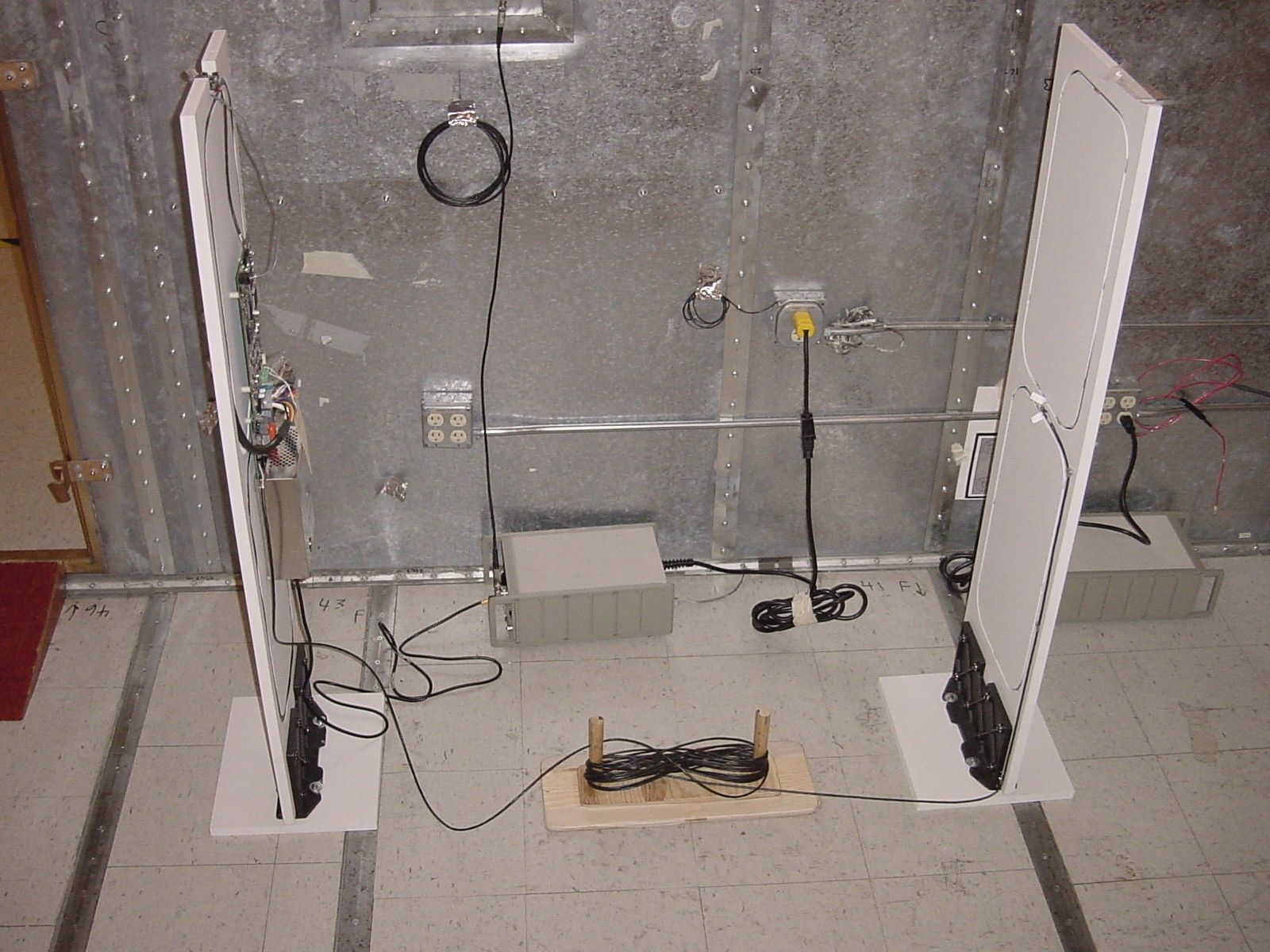
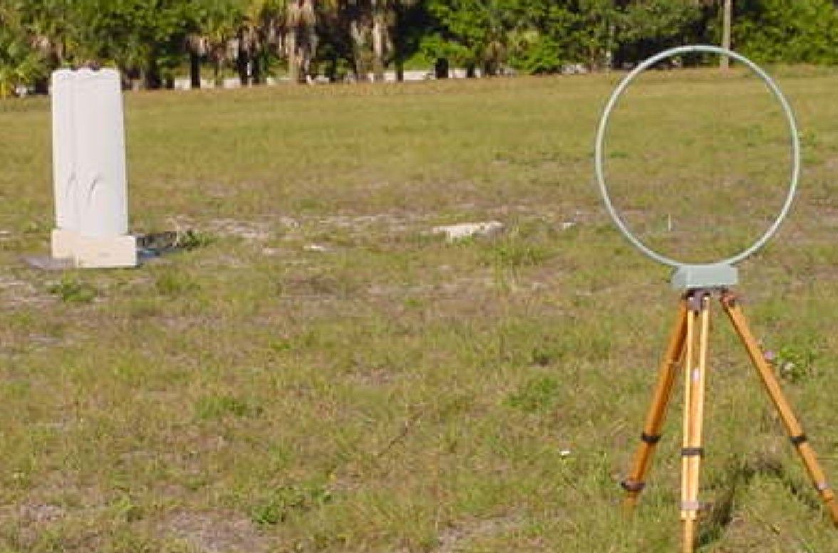
FCC ID: BVCUMEMAX2 1 COMPANY Sensormatic Electronics Corp. 951 Yamato Road Boca Raton, Florida PRODUCT TESTED UltraMax eMax II FCC ID: BVCUMEMAX2 FCC RULES 15.207, 15.209 TEST DATE August 22, September 24, 2001 SUBMITTED BY Donald J. Umbdenstock FCC ID: BVCUMEMAX2 2 INDEX I. SUMMARY OF RESULTS 3 II. GENERAL INFORMATION 3 Test Methodology 3 Test Facility 3 System Description 4 15.203 Compliance 4 III. CONDUCTED EMISSIONS TESTING, 15.207 4 IV. RADIATED EMISSIONS TESTING, 15.209 5 V. (This section intentionally blank) 5 VI. LIST OF MEASUREMENT EQUIPMENT 6 VII. DATA 7 Part A –Conducted Emissions 7 Part B –Radiated Emissions 8 FCC ID: BVCUMEMAX2 3 I. Summary of Results 47 CFR 15.207 CONDUCTED EMISSIONS COMPLIES 47 CFR 15.209 RADIATED EMISSIONS COMPLIES II. General Information 1.1 Test Methodology Both conducted and radiated emissions testing were performed according to the procedures in ANSI C63.4-1992, and the requirements of 15.31, 15.33, 15.35, 15.207, and 15.209. Radiated emissions measurements below 30 MHz were performed at a distance of 10 meters and the results extrapolated to the distance specified per 15.31 and 15.209. 1.2 Test Facility Measurements per 15.207 and 15.209 were performed at Sensormatic Electronics Corporation. The shielded room conducted emissions measurement facility is located at Sensormatic Electronics Corporation Headquarters at 951 Yamato Road, Boca Raton, Florida, 33431. The radiated emissions Open Area Test Site is located at Sensormatic Electronics Corporation manufacturing location, 6600 Congress Avenue, Boca Raton, Florida 33487. These sites have been found acceptable by and are on file with the FCC per FCC Registration Number 90925. FCC ID: BVCUMEMAX2 4 1.3 Test System Description. The system consists of a transmit antenna pedestal that also houses the transmitter and receiver circuitry and a receive antenna pedestal. The pedestal antennas are loop antennas. The receive antenna also comes in the form of a ferrite core antenna. The product tested was a pre-production unit built to production drawings. 15.203. The antenna is contained internally and is permanently attached, thus it is compliant with the requirements of this clause. III. Conducted Emissions 15.207. Conducted emissions data are presented in Section VII “Data”, Part A, Conducted Emissions. The product demonstrated compliance with the requirements. The product was tested at 120 V, 60 Hz. FCC ID: BVCUMEMAX2 5 IV. Radiated Emissions 15.209. Radiated emissions data for this product are presented in Section VII “Data”, Part B, Radiated Emissions. The product demonstrated compliance with the requirements. Radiated emissions measurements were performed at 10 and 20 meters. Propagation loss was determined measuring the emissions at 10 and 20 meters and extrapolating the results to 300 meters as per 15.31(f)(2). Maximum radiation was determined by first assessing symmetry while applying incremental rotation of the product. The product exhibited quadrant symmetry. Measurements were taken at radials of 22.5° throughout one quadrant; the measurement antenna was rotated for maximum pickup about the vertical axis of the measurement antenna at each radial. The maximum emission was determined to be with the measurement loop antenna in the vertical polarization, parallel to the plane of the transmit antenna. The product was tested at input voltages to the transformer ranging from 102 – 138 V, 60 Hz with no significant change in transmitter output. See Section VII, Part B. V. (This section intentionally left blank) FCC ID: BVCUMEMAX2 6 VI. LIST OF MEASURING EQUIPMENT The equipment used for determining compliance of the Ultra Post system with the requirements of 15.207 and 15.209 is marked with an “X” in the first column of the table below. Model Description Vendor Serial # X ALP -70 Loop Antenna Electro Metrics 163 3110B Biconnical Antenna Electro Metrics 1017 3146 Log Periodic Antenna EMCO 3909 3825/2 Line Imp Stable Network EMCO 1562 X 3816/2NM Line Imp Stable Network EMCO 9703 1064 6060B Frequency Generator Giga-tronics 5850202 FM2000 Isotropic Field Monitor Amplifier Research 15171 FP2000 Isotropic Field Probe Amplifier Research 15214 888 Leveler Amplifier Research 14998 75A220 Low Band Amplifier Amplifier Research 15208 10W1000A High Band Amplifier Amplifier Research 15138 PEFT Junior EFT Generator Haefely Trench 083 180-16 PEFT Junior Capacitive Cable Clamp Haefely Trench 083-078-31 NSG435 ESD Simulator Schaffner 1197 NSG431 ESD Simulator Schaffner 1267 X HP8591EM EMC Analyzer Hewlett - Packard 3520A00190 Power Source Pacific Instruments F-2031 EM Injection Clamp Fischer Cust. Comm. 30 FCC-801-M3-16 Coupling Decoupling Nwk Fischer Cust. Comm. 58 FCC-801-M3-16 Coupling Decoupling Nwk Fischer Cust. Comm. 59 F-33-1 RF Current Probe Fischer Cust. Comm. 304 EM 7600 Transient Limiter Electro-Metrics 187 Roberts Ant Tunable Dipole Set Compliance Design 003282 Roberts Ant Tunable Dipole Set Compliance Design 003283 HP8594E Spectrum Analyzer Hewlett Packard 3246A00300 X HP8447F Opt 64 Dual Preamplifier Hewlett Packard 2805A03473 FCC ID: BVCUMEMAX2 7 VII. Data Part A contains conducted emissions data; Part B contains magnetic field radiated emissions data. Part A Conducted Emissions Project Name Conducted Emissions FCC Class B Limit Filename EMaxII_CondEMI_FCC_9-24-01.doc EUT Name e-Max II Serial Number Prototype Engineer Guillermo Padulla Phone Number Date of Test 09/24/2001 3:01:36 PM Test Name Conducted Emission Reg. Technician Stephen Krizmanich Reviewer Don Umbdenstock Comments Line In: 120vac 60hz. No Ferrites. 40’ of interconnect cable fig. 8 on floor between pedestals. Short Communication cable in place. New Oscillator EMC60S5B-16.348Mhz. NOTE 1. Intentional Radiators Only: See FCC Part 15; Sect15.207; pp. 15-703 If the level of the emission measured using quasi-peak instrumentation is 6dB or more higher than the level of the same emission measured with instrumentation having an average detector and 9khz minim…
Text truncated - open the document above for the full version.
Contact Information
Applicant
Mark D. Alexis(Manager Regulatory Compliance)
Test Firm
Sensormatic Electronics CorporationWilliam Elliott
Technical Specifications
| # | Rule Parts | Frequency Range | Power Output |
|---|---|---|---|
| 1 | 15C | 0.0578 MHz - 0.0582 MHz | - |
Other Applications from Tyco Safety Products/Sensormatic

BVCIDX5000
Jun 23, 2026UHF RFID Reader
Equipment Class
DSS - Part 15 Spread Spectrum TransmitterBVCAMS1137H
Dec 22, 2025Anti Theft System - Electronic Asset Security
Equipment Class
FAP - Part 15 Anti-Pilferage DeviceBVCAMB9012
Sep 10, 2024Label Deactivator Controller
Equipment Class
DCD - Part 15 Low Power Transmitter Below 1705 kHz
BVC-4000-PI26
Sep 24, 2015RM2L-4000-P126, RM2-4000-P126
Equipment Class
DXX - Part 15 Low Power Communication Device Transmitter
BVCAMS90604
May 20, 2014Anti-pilferage Device
Equipment Class
FAP - Part 15 Anti-Pilferage Device