BVCUMPHSR-T
Tyco Safety Products/Sensormatic
Click to zoom
Application Details
- Equipment Class
- DXX - Part 15 Low Power Communication Device Transmitter
- Date of Grant
- May 13, 1999
- Application Purpose
- Original Equipment
- Date of Application
- Apr 05, 1999
- Frequency Range
- 902.00000000 - 928.00000000
- Country
- United States
Documents & Files
Document Text
Text extracted from the exhibit documents filed with the FCC. Open a document above to read the original.
Users Manual
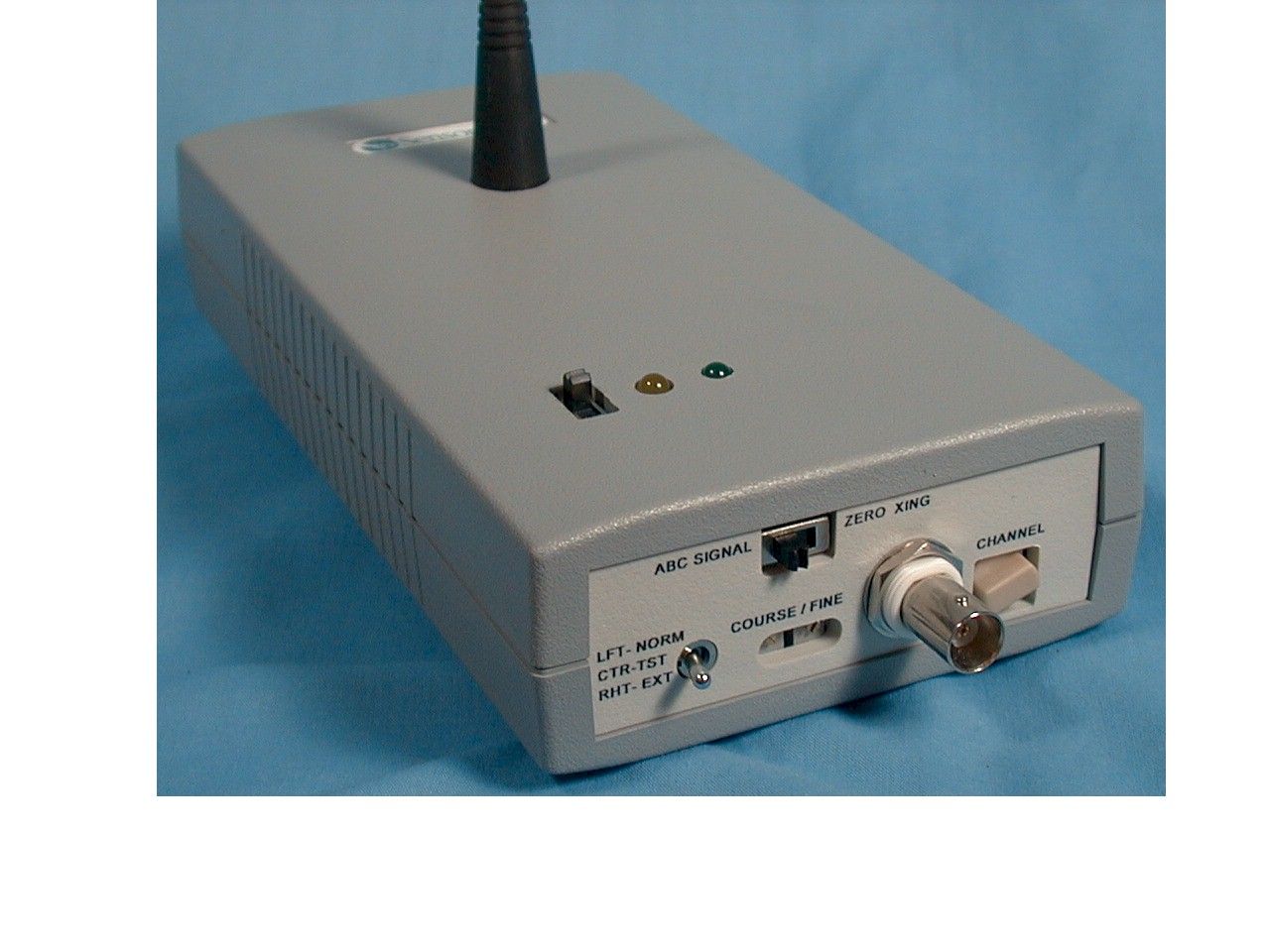
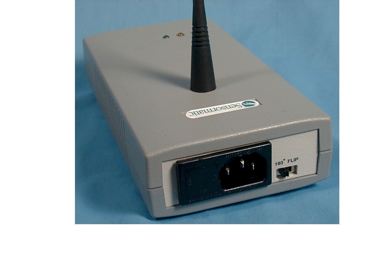
Operating Guide 8000-2574-22, Rev. A (4 pages) ULTRA•MAX PRODUCTS1 1 11 1 Ultra UltraUltra Ultra • •• • Max Phasing Max PhasingMax Phasing Max Phasing Tool (900MHz) Tool (900MHz)Tool (900MHz) Tool (900MHz) Kit 0100-2321-01 Case10400-1187-01 Transmitter (900MHz)20100-2320-01 Receiver (900MHz)10100-2319-01 Sense coil20300-2274-01 12' BNC cable20650-0211-01 3' BNC cable10650-0211-02 Antenna (900MHz)33411-0005-01 Bracket20400-1182-01 Battery14007-0004-01 Power cord26003-0007 Ultra • Max detectors and deactivators derive their timing from the zero crossing of the ac power line. Ultra • Max detectors and deactivators may interfere with each other if there are ac line phasing differences between systems. The Phasing tool is used to synchronize the timing of all Ultra • Max systems located in a store, shopping center, or mall. A reference system is selected and then all other systems are synchronized to the reference system. The basic steps to synchronize all systems are as follows: A. Set up a reference transmitter at the reference system. B. Synchronize all other systems within the range of the reference transmitter. C. Use the second transmitter to extend the range of the reference transmitter. Repeat steps B and C until all systems in the store, shopping center, or mall are synchronized. Phase all of the systems first! Don't spend a lot of time tuning systems until all systems have been phased. Cover as much area as possible from a single transmitter location. There will be some error build up for each time a new transmitter is used. If you have a team of CE’s with several phasing tools, you can efficiently phase an entire mall. See Phasing Team on page 4 . Before you begin, do the following: • Survey the site to identify the location and type of EAS systems present. Systems that can not be phased may need to be upgraded. Upgrading of older equipment should be planned in advance. • Locate all possible sources of 900 MHz interference including cellular, cordless and computer equipment. Where possible, avoid using either the transmitter or the receiver in those immediate areas. No interference has been found with wireless equipment but the presence of such equipment will reduce the effective range of the Phasing tool. • Based on the proximity of the systems to be phased, choose a starting reference system. This is often the most difficult part. Choosing the right reference system can minimize the amount of phasing required. Begin with steps A and B and then repeat steps C and B until all systems are synchronized. A. Setting up a reference transmitter A. Setting up a reference transmitterA. Setting up a reference transmitter A. Setting up a reference transmitter at the reference system. at the reference system.at the reference system. at the reference system. 1. Using the receiver, find the channel with minimal interference. Power on the receiver and rotate through the 8 available channels (position 0-7 only). Observe the signal strength indicator and select the channel with the lowest signal strength. Note: Channels with steady or fluctuating high levels of activity will not provide the maximum range. Figure 1. Receiver Signal strength indicator Channel selector Power on/off Battery (in back) 2OPERATING GUIDE PHASING TOOL (900MHZ) 8000-2574-22, REV. A 2. Set up the transmitter. a. Set the first transmitter to the same channel as the receiver. b. Locate a power outlet at or near the reference system and plug in the first transmitter. CAUTION: Make sure the power select fuse on both transmitters is set for the correct ac voltage. To change the setting, use the blade of a small scewdriver to pry out the power select module. Rotate and insert the module so that the correct voltage (115, 125, 230, 250) is opposite the arrow. Locate the transmitter in a clear and open area that will provide the best possible line of site to all of the systems to be phased. Note: Avoid locating the transmitter in the ceiling or any metal enclosed areas. c. Set the switches of the transmitter to Normal mode and ABC Signal . Figure 2. Transmitter 3. Verify receiver operation. a. On the receiver's signal strength indicator, you should see a steady, strong signal. b. Connect the output of the receiver to channel 1 of an oscilloscope with the short BNC cable and the sense coil to channel 2 with the long BNC cable. c. Verify that channel 1 shows the proper ABC signal from the transmitter. (One wide, 3ms, negative going pulse followed by two narrow, 1ms, negative going pulses with a separation of 5.556ms for 60Hz and 6.667ms for 50Hz.) Best viewed at 1ms/division. 4. Align the reference transmitter a. Beginning at the transmitter antenna of the reference system, place the sense coil against or near the transmitter coil. Position the coil for the strongest possible signal. Note: The sense coil is a cylindrical coil and is very orientation specific. It must be in the proper orientation for maximum sensitivity. b. Verify that channel 2 shows the proper transmitter burst signal. Note: In general, the reference system should be one with No Delay . If the system has been phased, you should consider first setting it back to the No Delay default. c. While watching the receiver signal and burst signal on the oscilloscope, adjust the Phase Adjustment pot on the first transmitter so that the burst signal starts at the Falling Edge (beginning) of any one of the three pulses. Use the “180 ° Flip” switch if more adjustment range is needed. Note: In general, you will want to make a coarse adjustment with scope at a large scale (e.g. 500 μ s or 1ms/division) and then fine tune the adjustment with the scope at 50 μ s/division. Note: Depending on the type of system being adjusted, there will be some timing jitter in the signals displayed. In this case, adjust the transmitter such that the jitter is divided equally between leading and lagging. (Average the variation.) Power on LED Transmit enable indicator (on = enabled) Transmit enable/ disa…
Text truncated - open the document above for the full version.
Users Manual
User’s Guide 8000-2668-01, Rev. A (2 pages) ULTRA•MAX EAS PRODUCTS1 1 11 1 Ultra•Max Ultra•MaxUltra•Max Ultra•Max Hand-Held Verifier Hand-Held VerifierHand-Held Verifier Hand-Held Verifier About the Unit About the UnitAbout the Unit About the Unit The Ultra•Max hand-held verifier is a battery- operated, rechargeable, device used to: • detect active Ultra•Max labels or tags at store exits so they can be returned to the checkout counter for proper deactivation or removal. • audit incoming merchandise for source tagging compliance. The verifier works by generating a short-range field and then listening for signal from an active Ultra•Max label or tag. If a signal is detected, the verifier alarms. The verifier consists of a: • Wand • Wall-mounted charger • Power supply Installing the Charger Installing the ChargerInstalling the Charger Installing the Charger IMPORTANT! To ensure installation complies with all applicable codes and regulations, install the charger exactly as follows: 1. Using two screws provided, mount charger vertically to any flat surface with its open end facing up (see diagram). 2. Plug cord of power supply into side of charger. 3. Plug power supply into an AC wall outlet. Green light on charger should light. Charging the Wand Charging the WandCharging the Wand Charging the Wand 1. With the lights on the wand facing you, slide handle of wand into tube of charger and push down. a. Top light on charger turns red to indicate charging, which can take up to 10 hours max. When top light turns green, wand is fully charged. Wand should be fully charged before using it for the first time. b. This product uses a nickel cadmium battery. To maximize battery life, fully discharge battery before recharging. c. Power supply may get slightly warm during charging (this is normal). 2. Remove wand from charger. Charge should last for about 5 hours. WARNING: Place wand in charger only for recharging, not for routine storage. If you want to use charger for storage, then unplug power supply when not recharging. Wand Charger Power Supply 2USER’S GUIDE ULTRA•MAX EAS PRODUCTS 8000-2668-01, REV. A Using the Wand Using the WandUsing the Wand Using the Wand You detect active labels and tags as follows: 1. Hold button on wand down. 2. The wand will go through an initialization routine (see below). 3. Continuing to hold the button down, move wand in a circular motion over item. If the red light on the wand glows and a steady beep occurs (with the green light remaining lit), then an active label or tag has been found. Initialization Routine Initialization RoutineInitialization Routine Initialization Routine The wand has a button, a buzzer, and two lights (red and green). When you first press down the button, the lights and buzzer go through a sequence as follows: a. Red flashes once b. Green flashes once c. Short beep occurs d. Green light glows steadily and remains on. The verifier is then ready to detect labels or tags. Note: Large metal surfaces can affect detection. The red light on the wand will blink when metal is detected; in which case, move the wand at least 1m (3') away from the metal and retry. If the green light blinks, then wand needs to be recharged. Specifications SpecificationsSpecifications Specifications AC power (N. America) .......120Vac, 1A (60Hz) Class 2 AC power (Europe) .............230Vac, 0.5A (50Hz) LPS Detection height ..................5cm to 10cm (2" to 4") Battery operating time .........5 hours Battery recharge time ..........10 hours max. Weight of wand ...................640g (22.6 oz) Weight of charger................240g (8.5 oz) Declarations DeclarationsDeclarations Declarations Regulatory Compliance Regulatory ComplianceRegulatory Compliance Regulatory Compliance EMC(wand & charger)........47 CFR, Part 15 I-ETS 300330 ETS 300683 Safety (power supply) ........Certified Class 2 EN60950 LPS Safety (wand & charger) ....EN60950 FCC COMPLIANCE: This equipment complies with Part 15 of the FCC rules for intentional radiators and Class A digital devices when installed and used in accordance with the instruction manual. Following these rules provides reasonable protection against harmful interference from equipment operated in a commercial area. This equipment should not be installed in a residential area as it can radiate radio frequency energy that could interfere with radio communications, a situation the user would have to fix at their own expense. EQUIPMENT MODIFICATION CAUTION: Equipment changes or modifications not expressly approved by Sensormatic Electronics Corporation, the party responsible for FCC compliance, could void the user's authority to operate the equipment and could create a hazardous condition. Other Declarations Other DeclarationsOther Declarations Other Declarations WARRANTY DISCLAIMER: Sensormatic Electronics Corporation makes no representation or warranty with respect to the contents hereof and specifically disclaims any implied warranties of merchantability or fitness for any particular purpose. Further, Sensormatic Electronics Corporation reserves the right to revise this publication and make changes from time to time in the content hereof without obligation of Sensormatic Electronics Corporation to notify any person of such revision or changes. LIMITED RIGHTS NOTICE: For units of the Department of Defense, all documentation and manuals were developed at private expense and no part of it was developed using Government Funds. The restrictions governing the use and disclosure of technical data marked with this legend are set forth in the definition of "limited rights" in paragraph (a) (15) of the clause of DFARS 252.227.7013. Unpublished - rights reserved under the Copyright Laws of the United States.
Operational Description
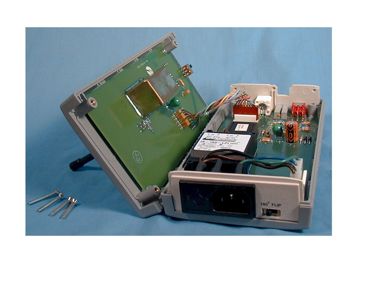
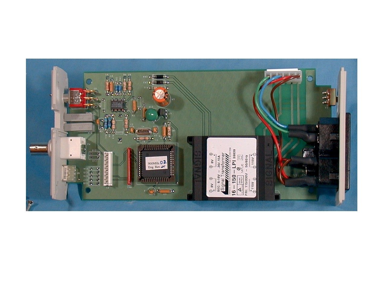
prec i se AC li ne re f erence, th us avo idi ng sys t em t o sys t em i n t erac ti on. All Ult ra *M a x systems are synchronized to the Zero Crossing of their AC power source with someinternal capabilities to phase shift from that reference. However, there are no system tosystem interconnections for precise synchronization of systems. The Ultra*MaxPhasing Kit uses an AC powered, 900 MHz transmitter to send a synchronization signalto a battery powered 900 MHz receiver. The transmitter uses an internal Zero Crossingdetector and phasing shifting capability to provide flexibility with existing systems. Amicroprocessor is used to generate a multi phase signal for use in multi phase powerenvironments.The Transmitter is used as follow, first the transmitter is connected to a near by powersource where it synchronizes to the zero crossing of the local power source. The outputof the transmitter is then adjusted by turning either the course or fine adjustment screwsso that matches a near by “reference” system. Once the Transmitter is adjusted it is leftuntil all near by equipment has been compared or adjusted to is output reference.
Operational Description
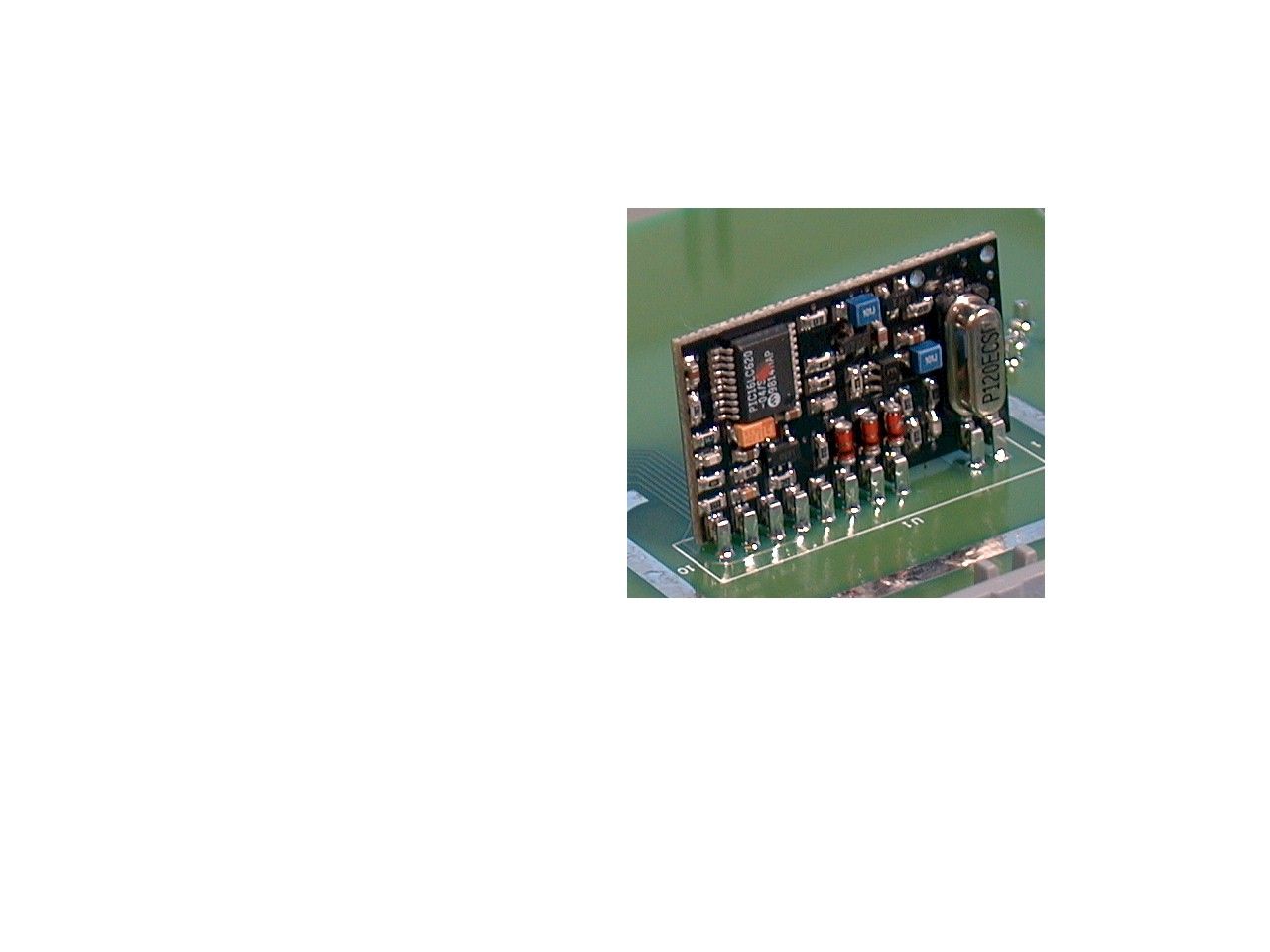
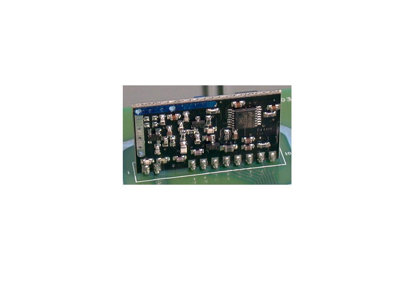
SECEAS Active Product Engineering Transmitter Theory of Operation The HP-TXM is a high performance, eight channel, FM transmitter capable of transmitting digital data. Digital information is modulated at the transmitter using FSK , the binary for of frequency modulation. An accurate 12.00MHz VCXO serves as the frequency reference for the transmitter. The modulation input pin is connect to the VCXO through a 25kHz two pole low pass filter. The low pass filter is used to shape the incoming date and limit the transmission bandwidth to 25 KHz. The reference frequency is directly modulated. The modulated 12.00 MHz reference frequency is applied to the phase locked loop. The PLL combined with the 902-928 MHz VCO forms a stable frequency synthesizer which is programmed to oscillate at a number of preset frequencies. An on board micro controller reads the channel selection lines and programs the PLL to the desired channel frequency. The micro controller also monitors the status of the PLL and indicates when the transmitter is stable and ready to transmit. A buffer amplifier is used to isolate the VCO from the antenna and to increase the output power of the transmitter. The output of the buffer amplifier is connected to a low pass filter which is used to suppress the harmonics emissions.
Schematics
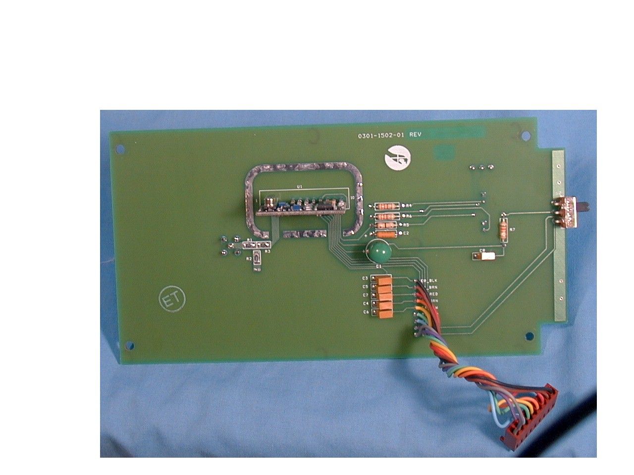
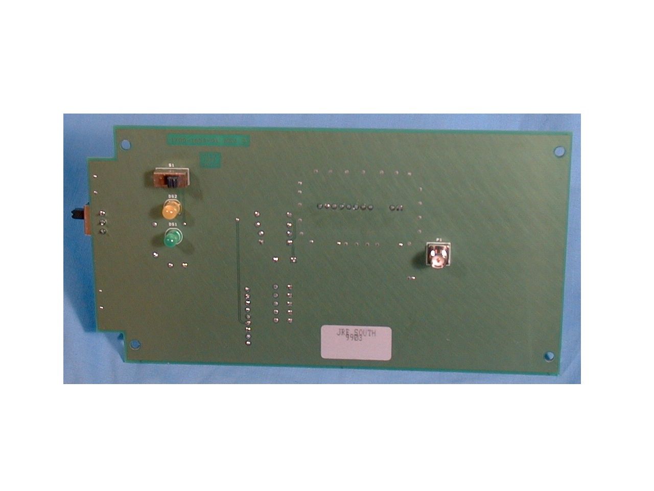
0301-1501 -01 3 Phaser, Transmitter, Power & Micro Module B 11 Wednesday, March 17, 1999 sec 951 Yamato Rd, Boca Raton, FL 33431 TitleSize Document Number Rev Date: Sheet of VCC VCC VCC VCC DGND DGND VCC DGND DGND DGND DGND DGND DGND DGND DGND DGND DGND VCC DGND DGND DGND VCC DGND DGND VCC DGND DGND DGND DGND DGND DGND DGND DGND DGND DGND DGND DGND DGND DGND DGND DGND VCC 240VAC 120VAC 120/240VAC R410K OHM4721-1002-5001% R72.2K OHM4711-2201-700 S45101-0059-01SLIDE 1 23 CR4RECT4800-0010 1 2 R1227 OHM4711-2709-700 CR3RECT4800-0010 1 2 R8150 OHM4711-1500-700 RV920K OHM4751-0028 1 2 3 R610K OHM4711-1002-700 C15100PF RV10500K OHM4751-0044 1 2 3 C18100PF1508-0065-01 R1320K OHM4711-2002-700 + - U2B393A3130-0393 56 7 C122PF1508-0088-01 + C10 100UF1532-0005 P1HDR2109-0201-08 123456789 CR5VOL4815-0010-01 12 Y1 8.00MHZ 2308-0035-01 21 C20 560PF1507-0028-01 P3 HDR 123456 CR2 SCHTKY4810-0012 12 + C9 100UF1536-0010-01 + C11 .1UF1532-0044-01 U3 78L053130-0057-01 3 2 1 VI GND VO 1346 52 7-8 S3TOGGLE5101-0030-01 + C21UF1532-0033-01 C422PF1508-0088-01 R110M OHM4711-1005-700 + C7 .1UF1532-0044-01 + C3 .1UF1532-0044-01 C19 560PF1507-0028-01 P2BNC2112-0009-04 12 C8.015UF 1507-0018-01 S55100-0020-01ROTARY 1 C1 4 2C28 1C142 C2 8 + - U2A393A3130-0393 32 1 84 68HC11 U1IC3130-0255-01 87 171918 2 34333243454749444648505251 31302928274241403938373635910111213141516202122232425354626 1 XTALEXTAL/RESET/IRQ/XIRQ MODB PA0PA1PA2PE0PE1PE2PE3PE4PE5PE6PE7VRHVRL PA3PA4PA5PA6PA7PB0PB1PB2PB3PB4PB5PB6PB7 PC0PC1PC2PC3PC4PC5PC6PC7PD0PD1PD2PD3PD4PD5 MODA E AS R/W VDD VSS + C5 .1UF1532-0044-01 CR1 SCHTKY4810-0012 12 R2 1K OHM4711-1001-700 R510K OHM4711-1002-700 RN147K OHM4715-0034-01 2 1 345678910 C14100PF C16100PF C12100PF C13100PF C17100PF R1140.2K OHM4721-4022-5001% + C6 .1UF1532-0044-01 T1P5604-0202-01 123 8 4 756 RN2_7 RN2_8 RN2_9 RN2_10 RN2_7 RN2_10 PDN PDN CTS CTS RN2_9RN2_8 Phase Adjust 115/230V,50/60Hz16VCT,150mA Sync Input3 Phase Signal Output Vref=4 V ZeroCrossingDetector 100240 Power Entry ModulePower Dynamics#42R34-3111-150 P4P3P2P1NE 120220 Zero Crossing Course Fine ChannelSelect PCB 1700-1653 -01 52PIN PLCC SOCKET2104-0043-06 To PCB Assy0301-1502-01 CS0 CS1 CS2 CTS PDN VCC GND MCOZXing LTR ER/ECN NO DECRIPTION DATE BY APP'D LAST USED REFERENCES C20U3R13S5CR5P3RV10Y1T1RN1 0301-1502 -01 3 Phaser, Transmitter, RF & Antenna Module B 11 Tuesday, March 16, 1999 sec 951 Yamato Rd, Boca Raton, FL 33431 TitleSize Document Number Rev Date: Sheet of DGND DGND DGND DGND DGND DGND DGND DGND DGND DGND DGNDDGND DGND DS1GREEN4820-0035-01 12 + C1100UF 1532-0005 + C2 .1UF 1532-0044-01 R713K OHM4711-1302-700 S25101-0059-01SLIDE 1 23 E0_BLKE1_BRNE2_REDE3_ORNE4_YLWE5_GRNE6_BLUE7_VLTE8_GRY S1SLIDE5101-0080-01 1 23 DS2YELLOW4820-0018-01 12 U1900MHZ3413-0004-01 321456789 10 CS0RF/ANTRF/GNDCS1CS2CTSPDNVCCGNDDATA IN R50 OHM4701-0000-000 C6100PF C4100PF C7100PF C8100PF1508-0065-01 C5100PF C3100PF R20 OHM4780-0000-700 R1 0 OHM 4780-0000-700 R3 0 OHM 4780-0000-700 R6330 OHM4711-3300-700 R4330 OHM4711-3300-700 1 2 P1SMA2111-0063-01 RF GroundPlane Reversed SMA ConnectorLINK# CONREVSMA001 PCB 1700-1654 -01 Mounted on the solder side Power On ABC/Xero Xing CS0CS1CS2CTSPDNVCCGNDMCOZXing TransmitterEnable Mounted on the solder side To PCB0301-1501-01 LTR ER/ECN NO DECRIPTION DATE BY APP'D Tx On LAST USED REFERENCES R7P1DS2C8S2U1
Test Report
ProductUltra Max Phaser TxS/N:0325-1T FCC IDBVCPHSR-T Date CompanySensormatic Electronics Corporation EngineerWilliam Burkholder Test LocationElite Electronics Engineering, Cocoa Beach File No.Cert. No. EMC 001045-NE Test PersonnelChuck Herhold Howard Herhold Tests per 47CFR15.31, 15.35, 15.249 - October 1998; ANSI C63.4 -1992 Test site OATS Test distance3 meters Bandwidth18.100 MHz Required Frequencies LowChannel 7, 903.350 MHz MiddleChannel 4, 909.450 MHz HighChannel 0, 921.450 MHz Signal Maximumdetermined by rotation of turntable and antenna elevation turntable height.8 meters Test Item Description 900 MHz transmitter, whip antenna, mains powered (120V/60Hz), 8 Channels synthesized, FSK modulated with 60 Hz zero crossing. April 1, 1999 Test DataChannel 7 Intentional Radiators: to 10th harmonic Frequency Measured Value Antenna Factor Cable Factor Pre Amp Factor Actual Value Limit MarginBWDetPol MHzdBuV/mdBdBdBdBuV/mdBuV/m 903.45059.727.21.60.088.5945.5120 KHz qpV 1806.90021.126.62.9-16.134.55419.51 MHz Ave V 2710.35025.728.23.7-15.741.95412.11 MHz Ave V 3613.80020.132.03.9-15.840.25413.81 MHz Ave V 4517.25021.732.76.9-14.047.3546.71 MHz Ave V 5420.70019.334.76.3-14.046.3547.71 MHz Ave V 6324.15016.734.76.4-13.644.2549.8100 KHz Ave V 7227.60016.436.37.5-14.046.2547.8100 KHz Ave V 8131.05016.237.08.7-14.847.1546.9100 KHz Ave V 9034.50015.737.68.8-14.947.2546.8100 KHz Ave V Bold,Italic=Ambient Reading 903.45054.027.21.60.082.89411.2120 KHz qpH 1806.90018.226.62.9-16.131.65422.41 MHz Ave H 2710.35021.528.23.7-15.737.75416.31 MHz Ave H 3613.80019.732.03.9-15.839.85414.21 MHz Ave H 4517.25019.932.76.9-14.045.5548.51 MHz Ave H 5420.70019.434.76.3-14.046.4547.61 MHz Ave H 6324.15016.434.76.4-13.643.95410.1100 KHz Ave H 7227.60016.336.37.5-14.046.1547.9100 KHz Ave H 8131.05015.937.08.7-14.846.8547.2100 KHz Ave H 9034.50015.637.68.8-14.947.1546.9100 KHz Ave H Bold,Italic=Ambient Reading Test DataChannel 4 Intentional Radiators: to 10th harmonic Frequency Measured Value Antenna Factor Cable Factor Pre Amp Factor Actual Value Limit MarginBWDetPol MHzdBuV/mdBdBdBdBuV/mdBuV/m 909.45060.427.31.60.089.3944.7120 KHz qpV 1818.90022.426.62.9-16.135.85418.21 MHz Ave V 2728.35026.228.23.7-15.742.45411.61 MHz Ave V 3637.80020.032.03.9-15.840.15413.91 MHz Ave V 4547.25020.032.66.9-14.045.5548.51 MHz Ave V 5456.70019.134.76.3-14.046.1547.91 MHz Ave V 6366.15016.934.76.4-13.644.4549.6100 KHz Ave V 7275.60016.436.37.5-14.046.2547.8100 KHz Ave V 8185.05015.637.08.8-14.946.5547.5100 KHz Ave V 9094.50015.637.68.7-14.947.0547.0100 KHz Ave V Bold,Italic=Ambient Reading 909.45054.927.31.60.083.89410.2120 KHz qpH 1818.90018.426.62.9-16.131.85422.21 MHz Ave H 2728.35024.828.23.7-15.741.05413.01 MHz Ave H 3637.80019.532.03.9-15.839.65414.41 MHz Ave H 4547.25019.932.66.9-14.045.4548.61 MHz Ave H 5456.70019.034.76.3-14.046.0548.01 MHz Ave H 6366.15016.834.76.4-13.644.3549.7100 KHz Ave H 7275.60016.336.37.5-14.046.1547.9100 KHz Ave H 8185.05015.737.08.8-14.946.6547.4100 KHz Ave H 9094.50015.737.68.7-14.947.1546.9100 KHz Ave H Bold,Italic=Ambient Reading Test DataChannel 0 Intentional Radiators: to 10th harmonic Frequency Measured Value Antenna Factor Cable Factor Pre Amp Factor Actual Value Limit MarginBWDetPol MHzdBuV/mdBdBdBuV/mdBuV/m 921.45059.727.41.70.088.8945.2120 KHz qpV 1842.90024.226.83.0-16.038.05416.01 MHz Ave V 2764.35032.329.33.8-15.749.7544.31 MHz Ave V 3685.80019.532.34.2-15.640.45413.61 MHz Ave V 4607.25021.432.86.7-14.046.9547.11 MHz Ave V 5528.70018.834.76.3-13.945.9548.11 MHz Ave V 6450.15018.034.86.5-13.745.6548.4100 KHz Ave V 7371.60015.636.57.7-14.145.7548.3100 KHz Ave V 8293.05015.537.18.8-14.946.5547.5100 KHz Ave V 9214.50015.337.68.7-14.946.7547.3100 KHz Ave V Bold,Italic=Ambient Reading 921.45053.927.41.70.083.09411.0120 KHz qpH 1842.90018.726.83.0-16.032.55421.51 MHz Ave H 2764.35025.129.33.8-15.742.55411.51 MHz Ave H 3685.80019.132.34.2-15.640.05414.01 MHz Ave H 4607.25019.832.86.7-14.045.3548.71 MHz Ave H 5528.70019.134.76.3-13.946.2547.81 MHz Ave H 6450.15018.034.86.5-13.745.6548.4100 KHz Ave H 7371.60015.636.57.7-14.145.7548.3100 KHz Ave H 8293.05014.837.18.8-14.945.8548.2100 KHz Ave H 9214.50015.137.68.7-14.946.5547.5100 KHz Ave H Bold,Italic=Ambient Reading Transmitter Fundamental, Low Line (97 VAC, -15%) Channel 7 Frequency Measured Value Antenna Factor Cable Factor Pre Amp Factor Actual Value Limit MarginBWDetPol MHzdBuV/mdBdBdBdBuV/mdBuV/m 903.45057.527.2001.6000.00086.3947.7120 KHz qpV 903.45052.427.2001.6000.00081.29412.8120 KHz qpH Channel 4 Frequency Measured Value Antenna Factor Cable Factor Pre Amp Factor Actual Value Limit MarginBWDetPol MHzdBuV/mdBdBdBdBuV/mdBuV/m 909.45058.727.3001.6000.00087.6946.4120 KHz qpV 909.45052.427.3001.6000.00081.39412.7120 KHz qpH Channel 0 Frequency Measured Value Antenna Factor Cable Factor Pre Amp Factor Actual Value Limit MarginBWDetPol MHzdBuV/mdBdBdBdBuV/mdBuV/m 921.45058.827.4001.7000.00087.9946.1120 KHz qpV 921.45052.927.4001.7000.00082.09412120 KHz qpH Transmitter Fundamental, High Line (134 VAC, +15%) Channel 7 Frequency Measured Value Antenna Factor Cable Factor Pre Amp Factor Actual Value Limit MarginBWDetPol MHzdBuV/mdBdBdBdBuV/mdBuV/m 903.45057.627.21.60.086.4947.6120 KHz qpV 903.45052.427.21.60.081.29412.8120 KHz qpH Channel 4 Frequency Measured Value Antenna Factor Cable Factor Pre Amp Factor Actual Value Limit MarginBWDetPol MHzdBuV/mdBdBdBdBuV/mdBuV/m 909.45058.627.31.60.087.5946.5120 KHz qpV 909.45052.727.31.60.081.69412.4120 KHz qpH Channel 0 Frequency Measured Value Antenna Factor Cable Factor Pre Amp Factor Actual Value Limit MarginBWDetPol MHzdBuV/mdBdBdBdBuV/mdBuV/m 921.45058.727.41.70.087.8946.2120 KHz qpV 921.45053.127.41.70.082.29411.8120 KHz qpH Actual Value = Measured value + cable factor + PreAmp Factor Test Equipment Used HP 8566A Spectrum Analyzer, SN 2043A0045 HP 85650A Quasi-Peak Adapter, SN 2209A01339 EMCO, Model 3105 Double ridged guide antenna, SN 2035 Empire Devices(NDK-1) Model DM-205/T3 Di-Pole Antenna, SN 515 M…
Text truncated - open the document above for the full version.
Test Report
Sensormatic Electronics Corporation Conducted Emissions Test 1 Project Name Phaser TX 900MHz Cndtd Emissions Filename EUT Name Phaser 900Mhz Transmitter Serial Number 0325-IT Engineer Bill Burkholder Phone Number Date of Test 4/8/99 10:29:24 AM Test Name 450kHz-30MHz, L1 = L2 Reg. Technician Steve Krizmanich FCC ID BVCUMPHSR-T Comments Phaser 900MHz 120VAC 60Hz SEC P/N 0100-2320-01 Rev:A0 Signal List Figure 1. L1 Full Range
Contact Information
Applicant
Mark D. Alexis(Manager Regulatory Compliance)
Test Firm
Elite Electronic Engineering Co.Daniel Crowder
Technical Specifications
| # | Rule Parts | Frequency Range | Power Output |
|---|---|---|---|
| 1 | 15C | 902 MHz - 928 MHz | - |
Other Applications from Tyco Safety Products/Sensormatic

BVCIDX5000
Jun 23, 2026UHF RFID Reader
Equipment Class
DSS - Part 15 Spread Spectrum TransmitterBVCAMS1137H
Dec 22, 2025Anti Theft System - Electronic Asset Security
Equipment Class
FAP - Part 15 Anti-Pilferage DeviceBVCAMB9012
Sep 10, 2024Label Deactivator Controller
Equipment Class
DCD - Part 15 Low Power Transmitter Below 1705 kHz
BVC-4000-PI26
Sep 24, 2015RM2L-4000-P126, RM2-4000-P126
Equipment Class
DXX - Part 15 Low Power Communication Device Transmitter
BVCAMS90604
May 20, 2014Anti-pilferage Device
Equipment Class
FAP - Part 15 Anti-Pilferage Device