BY4-DIR300Digital Remote Control Extender
Trans Electric Co., Ltd.
Click to zoom
Application Details
- Equipment Class
- DSC - Part 15 Security/Remote Control Transmitter
- Date of Grant
- May 10, 2011
- Application Purpose
- Original Equipment
- Date of Application
- May 10, 2011
- Equipment Note
- Digital Remote Control Extender
- Frequency Range
- 433.92000000 - 433.92000000
- Company
- Trans Electric Co., Ltd.
- Country
- Taiwan
Documents & Files
Document Text
Text extracted from the exhibit documents filed with the FCC. Open a document above to read the original.
Users Manual
DIGITAL REMOTE CONTROL EXTENDER MODEL :DIR-300 OWNERS MANUAL LOCATION OF CONTROLS Transmitter Side Receiver Side DC Power DC Power IR Probe Transmitter and Receiver Front Infrared Remote Control Antenna Remote Control Indicators & IR Transmitter/Receiver Accessory DC 12 V AC 120V or 230V Adaptor x2 Infrared Extender X 3 1,1.5,2m in len gth 1 CAUTION: Federal Communication Commission Interference Statement This equipment has been tested and found to comply with the limits for a Class B digital device, pursuant to Part 15 of the FCC Rules. These limits are designed to provide reasonable protection against harmful interference in a residential installation. This equipment generates, uses and can radiate radio frequency energy and, if not installed and used in accordance with the instructions, may cause harmful interference to radio communications. However, there is no guarantee that interference will not occur in a particular installation. If this equipment does cause harmful interference to radio or television reception, which can be determined by turning the equipment off and on, the user is encouraged to try to correct the interference by one of the following measures: Reorient or relocate the receiving antenna. Increase the separation between the equipment and receiver. Connect the equipment into an outlet on a circuit different from that to which the receiver is connected. Consult the dealer or an experienced radio/TV technician for help. FCC Caution: Any changes or modifications not expressly approved by the party responsible for compliance could void the user's authority to operate this equipment. This device complies with Part 15 of the FCC Rules. Operation is subject to the following two conditions: (1) This device may not cause harmful interference, and (2) this device must accept any interference received, including interference that may cause undesired operation. 2 IMPORTANT SAFETY PRECAUTIONS To prevent fire or shock hazard, do not submerge or expose this product to water. To avoid electric shock, do not open the units. The DIR-300 contains no user serviceable parts. Doing so will void the warranty. Use only the power supply provided with the DIR-300 Do not overload wall outlets or extension cords. If you are experiencing difficulty with this product, do not attempt to service it yourself. Please call your vendor for assistance. Product Description The DIR-300 Wireless Infrared Remote Control Extender enables you to extend the range of your present Infrared Remote Control so that you can operate VCRs, stereos, Cable Converter, Satellite receivers, etc., virtually anywhere in the home. Applications The remote operation of electronics products that utilize IR (Infrared) remote control technology such as: Satellite Receivers Television VCR's (Video Cassette Recorders) CDs (Compact Disc) DVD's (Digital Video Disc) LDP's (Laser Disc Players) Cable Converter Boxes Audio / Hi-Fi Stereo Systems Wireless Video Sender Systems Any IR Remote Controlled Devices 3 APPLICATION DIAGRAM IR Signal RFSignal 1. Stereo system with remote control: DIR-300 Receiver Wire to Extension Speaker Probe Stereo Wall IR Remote Control DIR-300 Transmitter 2. DSS / Satellite Receiver with remote control: 2nd TV DSS or Satellite Receiver Wall DIR-300 Receiver IR Remote Control DIR-300 Transmitter 4 Installation & Operation Guide Receiver Picture 1 Picture 2 Working with extender probe Antenna Power Adaptor (Using IR ) Make sure the IR probe is affixed toward IR sensor receiving Window with proper position (within 0.5M and working angles +/- 15°). Keep Vertical Picture 3 Picture 4 Working without extender probe Working without extender probe Side View 5.7 M 6 M 0.3 Not less than 0.3M and not more than 6M Working Angle not more than +/- 15° Working Angle not more than +/- 15° 5 Transmitter Picture 6 Picture 5 Working Angle not more than +/- 15° Antenna Power Adaptor Keep Vertical Remote Control Picture 7 Antenna Distance Not less than 0.3M and not more than 5M Working Angle not more than +/- 15° 6 Care and Maintenance Keep the DIR-300 Remote Extender dry. If it gets wet, wipe it dry immediately. Use and store the DIR-300 only in normal temperature environments. Extreme temperature can shorten the life of electronic devices Handle the DIR-300 gently and carefully. Dropping it can damage the circuit board and can cause it to work improperly. Keep the DIR-300 away from dust and dirt, which can cause premature wear of parts. Wipe the DIR-300 with a damp cloth occasionally to keep it looking new. Do not use harsh chemicals, cleaning solvents, or strong detergents. Specifications Operating Voltage .110 VAC, 60Hz/230V 50Hz DC 12V, 250mA Power Consumption (pair).............................. .....3 Watts Max Transmission Frequency........ .433.92MHz+/-1MHz Power Gain......................................................................10dBm Effective operating range....................... ... ....about 100M (clear line of sight) 7
Users Manual
DIGITAL REMOTE CONTROL EXTENDER MODEL :DIR-500 OWNERS MANUAL LOCATION OF CONTROLS Transmitter Side Receiver Side DC Power DC Power IR Probe Transmitter and Receiver Front Infrared Remote Control Antenna Remote Control Indicators & IR Transmitter/Receiver Accessory DC 12 V AC 120V Adaptor x2 Infrared Extender X 3 1,1.5,2m in len gth 1 CAUTION: Federal Communication Commission Interference Statement This equipment has been tested and found to comply with the limits for a Class B digital device, pursuant to Part 15 of the FCC Rules. These limits are designed to provide reasonable protection against harmful interference in a residential installation. This equipment generates, uses and can radiate radio frequency energy and, if not installed and used in accordance with the instructions, may cause harmful interference to radio communications. However, there is no guarantee that interference will not occur in a particular installation. If this equipment does cause harmful interference to radio or television reception, which can be determined by turning the equipment off and on, the user is encouraged to try to correct the interference by one of the following measures: Reorient or relocate the receiving antenna. Increase the separation between the equipment and receiver. Connect the equipment into an outlet on a circuit different from that to which the receiver is connected. Consult the dealer or an experienced radio/TV technician for help. FCC Caution: Any changes or modifications not expressly approved by the party responsible for compliance could void the user's authority to operate this equipment. This device complies with Part 15 of the FCC Rules. Operation is subject to the following two conditions: (1) This device may not cause harmful interference, and (2) this device must accept any interference received, including interference that may cause undesired operation. 2 IMPORTANT SAFETY PRECAUTIONS TO PREVENT FIRE OR SHOCK HAZARD, DO NOT SUBMERGE OR EXPOSE THIS PRODUCT TO WATER. TO AVOID ELECTRIC SHOCK, DO NOT OPEN THE UNITS. THE DIR-500 CONTAINS NO USER SERVICEABLE PARTS. DOING SO WILL VOID THE WARRANTY. USE ONLY THE POWER SUPPLY PROVIDED WITH THE DIR-500 DO NOT OVERLOAD WALL OUTLETS OR EXTENSION CORDS. IF YOU ARE EXPERIENCING DIFFICULTY WITH THIS PRODUCT, DO NOT ATTEMPT TO SERVICE IT YOURSELF. PLEASE CALL YOUR VENDOR FOR ASSISTANCE. Product Description The DIR-500 Wireless Infrared Remote Control Extender enables you to extend the range of your present Infrared Remote Control so that you can operate VCRs, stereos, Cable Converter, Satellite receivers, etc., virtually anywhere in the home. Applications The remote operation of electronics products that utilize IR (Infrared) remote control technology such as: Satellite Receivers Television VCR's (Video Cassette Recorders) CDs (Compact Disc) DVD's (Digital Video Disc) LDP's (Laser Disc Players) Cable Converter Boxes Audio / Hi-Fi Stereo Systems Wireless Video Sender Systems Any IR Remote Controlled Devices 3 APPLICATION DIAGRAM IR Signal RFSignal 1. Stereo system with remote control: DIR-500 Receiver Wire to Extension Speaker Probe Stereo Wall IR Remote Control DIR-500 Transmitter 2. DSS / Satellite Receiver with remote control: 2nd TV DSS or Satellite Receiver Wall IR Remote Control DIR-500 Receiver DIR-500 Transmitter 4 Installation & Operation Guide Receiver Picture 1 Picture 2 Working with extender probe Antenna Power Adaptor (Using IR ) Make sure the IR probe is affixed toward IR sensor receiving Window with proper position (within 0.5M and working angles +/- 15°). Keep Vertical Picture 3 Picture 4 Working without extender probe Working without extender probe Side View 6.6 M 7 M 0.3 Not less than 0.3M and not more than 7M Working Angle not more than +/- 15° Working Angle not more than +/- 15° 5 Transmitter Picture 6 Picture 5 Working Angle not more than +/- 15° Antenna Power Adaptor Keep Vertical Remote Control Picture 7 Antenna Distance Not less than 0.3M and not more than 5M Working Angle not more than +/- 15° 6 Care and Maintenance Keep the DIR-500 Remote Extender dry. If it gets wet, wipe it dry immediately. Use and store the DIR-500 only in normal temperature environments. Extreme temperature can shorten the life of electronic devices Handle the DIR-500 gently and carefully. Dropping it can damage the circuit board and can cause it to work improperly. Keep the DIR-500 away from dust and dirt, which can cause premature wear of parts. Wipe the DIR-500 with a damp cloth occasionally to keep it looking new. Do not use harsh chemicals, cleaning solvents, or strong detergents. Specifications Operating Voltage .110 VAC, 60Hz/ DC 12V, 250mA Power Consumption (pair).............................. .....3 Watts Max Transmission Frequency........ .433.92MHz+/-1MHz Power Gain......................................................................10dBM Effective operating range....................... ... ....about 100M (clear line of sight) 7
Users Manual
Wireless IR Remote Controller Extender MODEL :MIR-500 OWNERS MANUAL LOCATION OF CONTROLS Transmitter Side Receiver Side DC Power DC Power IR Probe Transmitter and Receiver Front Infrared Remote Control Antenna Remote Control Indicators & IR Transmitter/Receiver Accessory DC 12 V AC 120V Adaptor x2 Infrared Extender X 3 1,1.5,2m in len gth 1 CAUTION: Federal Communication Commission Interference Statement This equipment has been tested and found to comply with the limits for a Class B digital device, pursuant to Part 15 of the FCC Rules. These limits are designed to provide reasonable protection against harmful interference in a residential installation. This equipment generates, uses and can radiate radio frequency energy and, if not installed and used in accordance with the instructions, may cause harmful interference to radio communications. However, there is no guarantee that interference will not occur in a particular installation. If this equipment does cause harmful interference to radio or television reception, which can be determined by turning the equipment off and on, the user is encouraged to try to correct the interference by one of the following measures: Reorient or relocate the receiving antenna. Increase the separation between the equipment and receiver. Connect the equipment into an outlet on a circuit different from that to which the receiver is connected. Consult the dealer or an experienced radio/TV technician for help. FCC Caution: Any changes or modifications not expressly approved by the party responsible for compliance could void the user's authority to operate this equipment. This device complies with Part 15 of the FCC Rules. Operation is subject to the following two conditions: (1) This device may not cause harmful interference, and (2) this device must accept any interference received, including interference that may cause undesired operation. 2 IMPORTANT SAFETY PRECAUTIONS TO PREVENT FIRE OR SHOCK HAZARD, DO NOT SUBMERGE OR EXPOSE THIS PRODUCT TO WATER. TO AVOID ELECTRIC SHOCK, DO NOT OPEN THE UNITS. THE MIR-500 CONTAINS NO USER SERVICEABLE PARTS. DOING SO WILL VOID THE WARRANTY. USE ONLY THE POWER SUPPLY PROVIDED WITH THE MIR-500 DO NOT OVERLOAD WALL OUTLETS OR EXTENSION CORDS. IF YOU ARE EXPERIENCING DIFFICULTY WITH THIS PRODUCT, DO NOT ATTEMPT TO SERVICE IT YOURSELF. PLEASE CALL YOUR VENDOR FOR ASSISTANCE. Product Description The MIR-500 Wireless Infrared Remote Control Extender enables you to extend the range of your present Infrared Remote Control so that you can operate VCRs, stereos, Cable Converter, Satellite receivers, etc., virtually anywhere in the home. Applications The remote operation of electronics products that utilize IR (Infrared) remote control technology such as: Satellite Receivers Television VCR's (Video Cassette Recorders) CDs (Compact Disc) DVD's (Digital Video Disc) LDP's (Laser Disc Players) Cable Converter Boxes Audio / Hi-Fi Stereo Systems Wireless Video Sender Systems Any IR Remote Controlled Devices 3 APPLICATION DIAGRAM IR Signal RF Signal 1. Stereo system with remote control: MIR-500 Receiver Wire to Extension Speaker Probe Stereo Wall IR Remote Control MIR-500 Transmitter 2. DSS / Satellite Receiver with remote control: 2nd TV DSS or Satellite Receiver Wall IR Remote Control MIR-500 Receiver MIR-500 Transmitter 4 Installation & Operation Guide Receiver Picture 1 Picture 2 Working with extender probe Antenna Power Adaptor (Using IR ) Make sure the IR probe is affixed toward IR sensor receiving Window with proper position (within 0.5M and working angles +/- 15°). Keep Vertical Picture 3 Picture 4 Working without extender probe Working without extender probe Side View 6.6 M 7 M 0.3 Not less than 0.3M and not more than 7M Working Angle not more than +/- 15° Working Angle not more than +/- 15° 5 Transmitter Picture 6 Picture 5 Working Angle not more than +/- 15° Antenna Power Adaptor Keep Vertical Remote Control Picture 7 Antenna Distance Not less than 0.3M and not more than 5M Working Angle not more than +/- 15° 6 Care and Maintenance Keep the MIR-500 Remote Extender dry. If it gets wet, wipe it dry immediately. Use and store the MIR-500 only in normal temperature environments. Extreme temperature can shorten the life of electronic devices Handle the MIR-500 gently and carefully. Dropping it can damage the circuit board and can cause it to work improperly. Keep the MIR-500 away from dust and dirt, which can cause premature wear of parts. Wipe the MIR-500 with a damp cloth occasionally to keep it looking new. Do not use harsh chemicals, cleaning solvents, or strong detergents. Specifications Operating Voltage .110 VAC, 60Hz/ DC 12V, 250mA Power Consumption (pair).............................. .....3 Watts Max Transmission Frequency........ .433.92MHz+/-1MHz Power Gain......................................................................10dBM Effective operating range....................... ... ....about 100M (clear line of sight) 7
External Photos
Page 1 CONSTRUCTION PHOTOS OF EUT Mode No.: DIR-300 TX Page 2 Mode No.: DIR-500 TX Page 3 Page 4 Page 5 Page 6
Internal Photos
Page 1 CONSTRUCTION PHOTOS OF EUT Mode No.: DIR-300 TX Page 2 Page 3 Mode No.: DIR-500 TX Page 4
Test Report
Report No.: RF110411E03 1 Report Format Version 4.0.0 FCC TEST REPORT REPORT NO.: RF110411E03 MODEL NO.: DIR-300 TX, DIR-500 TX, MIR-500 TX FCC ID : BY4-DIR300 RECEIVED: Apr. 11, 2011 TESTED: Apr. 25 to May 02, 2011 ISSUED: May 09, 2011 APPLICANT : Trans Electric Co., Ltd. ADDRESS : 771,Sec.2 Chungsan Rd, Huatang,Changhua, Taiwan. ISSUED BY: Bureau Veritas Consumer Products Services (H.K.) Ltd., Taoyuan Branch Hsin Chu Laboratory LAB ADDRESS: No. 81-1, Lu Liao Keng, 9th Ling, Wu Lung Tsuen, Chiung Lin Hsiang, Hsin Chu Hsien 307, Taiwan This test report consists of 35 pages in total. It may be duplicated completely for legal use with the approval of the applicant. It should not be reproduced except in full, without the written approval of our laboratory. The client should not use it to claim product endorsement by TAF or any government agencies. The test results in the report only apply to the tested sample. Report No.: RF110411E03 2 Report Format Version 4.0.0 Table of Contents RELEASE CONTROL RECORD.................................................................................3 1 CERTIFICATION.............................................................................................4 2 SUMMARY OF TEST RESULTS.....................................................................5 2.1 MEASUREMENT UNCERTAINTY..................................................................5 3 GENERAL INFORMATION.............................................................................6 3.1 GENERAL DESCRIPTION OF EUT................................................................6 3.2 DESCRIPTION OF TEST MODES..................................................................7 3.2.1 TEST MODE APPLICABILITY AND TESTED CHANNEL DETAIL..................8 3.3 GENERAL DESCRIPTION OF APPLIED STANDARDS...............................10 3.4 DESCRIPTION OF SUPPORT UNITS...........................................................11 3.5 CONFIGURATION OF SYSTEM UNDER TEST...........................................12 4 TEST PROCEDURE AND RESULT..............................................................14 4.1 RADIATED EMISSION MEASUREMENT.....................................................14 4.1.1 LIMITS OF RADIATED EMISSION MEASUREMENT...................................19 4.1.2 TEST INSTRUMENT.....................................................................................20 4.1.3 TEST PROCEDURE.....................................................................................21 4.1.4 DEVIATION FROM TEST STANDARD.........................................................21 4.1.5 TEST SETUP................................................................................................22 4.1.6 EUT OPERATING CONDITION....................................................................22 4.1.7 TEST RESULTS............................................................................................23 4.2 20dB OCCUPIED BANDWIDTH MEASUREMENT......................................27 4.2.1 LIMITS OF EMISSION BANDWIDTH MEASUREMENT...............................27 4.2.2 TEST INSTRUMENT.....................................................................................27 4.2.3 TEST PROCEDURE.....................................................................................27 4.2.4 DEVIATION FROM TEST STANDARD.........................................................28 4.2.5 TEST SETUP................................................................................................28 4.2.6 TEST RESULTS............................................................................................28 4.3 DEACTIVATION TIME...................................................................................30 4.3.1 LIMITS OF DEACTIVATION TIME MEASUREMENT...................................30 4.3.2 TEST INSTRUMENTS..................................................................................30 4.3.3 TEST PROCEDURES...................................................................................30 4.3.4 DEVIATION FROM TEST STANDARD.........................................................30 4.3.5 TEST SETUP................................................................................................31 4.3.6 TEST RESULTS............................................................................................31 5 PHOTOGRAPHS OF THE TEST CONFIGURATION....................................33 6 INFORMATION ON THE TESTING LABORATORIES..................................34 7 APPENDIX A - MODIFICATIONS RECORDERS FOR ENGINEERING CHANGES TO THE EUT BY THE LAB..........................................................35 Report No.: RF110411E03 3 Report Format Version 4.0.0 RELEASE CONTROL RECORD ISSUE NO. REASON FOR CHANGE DATE ISSUED RF110411E03 Original release May 09, 2011 Report No.: RF110411E03 4 Report Format Version 4.0.0 1 CERTIFICATION PRODUCT: Digital Remote Control Extender BRAND NAME: PX MODEL NO: DIR-300 TX, DIR-500 TX, MIR-500 TX TEST SAMPLE: ENGINEERING SAMPLE APPLICANT: Trans Electric Co., Ltd. TESTED: Apr. 25 to May 02, 2011 STANDARDS: FCC Part 15, Subpart C (Section 15.231) ANSI C63.4-2003 ANSI C63.10-2009 The above equipment (model: DIR-300 TX, DIR-500 TX) have been tested by Bureau Veritas Consumer Products Services (H.K.) Ltd., Taoyuan Branch, and found compliance with the requirement of the above standards. The test record, data evaluation & Equipment Under Test (EUT) configurations represented herein are true and accurate accounts of the measurements of the sample’s EMC characteristics under the conditions specified in this report. PREPARED BY : , DATE: May 09, 2011 ( Carol Liao, Specialist ) APPROVED BY : , DATE: May 09, 2011 ( May Chen, Deputy Manager ) Report No.: RF110411E03 5 Report Format Version 4.0.0 2 SUMMARY OF TEST RESULTS The EUT has been tested according to the following specifications: APPLIED STANDARD: FCC Part 15, Subpart C (Section 15.231) STANDARD SECTION TEST TYPE AND LIMIT RESULT REMARK 15.207 AC Pow…
Text truncated - open the document above for the full version.
Test Setup Photos
1 PHOTOGRAPHS OF THE TEST CONFIGURATION CONDUCTED EMISSION TEST 2 RADIATED EMISSION TEST
Contact Information
Applicant
Grace Wang(Vice-General Manager, Intel' sales Dept.)
Technical Contact
Bureau Veritas CPS (H.K.) Ltd. Taoyuan BranchHank Chung
[email protected]886-3-593-5343
81-1, Lu Laio Keng, 9th Ling, Wu Lung Tsuen, Chiun · Hsinchu Hsien · Taiwan
Non-Technical Contact
Bureau Veritas CPS (H.K.) Ltd. Taoyuan BranchNatacha Chen
[email protected]886-3-3183232
Test Firm
Bureau Veritas CPS (H.K.) Ltd. Taoyuan BranchRichard Chen
Technical Specifications
| # | Rule Parts | Frequency Range | Power Output |
|---|---|---|---|
| 1 | 15.231 | 433.92 MHz - 433.92 MHz | - |
Other Applications from Trans Electric Co., Ltd.
BY4WTR1500C
Sep 18, 2024Wireless HD Transmitter & Receiver Kit
Equipment Class
NII - Unlicensed National Information Infrastructure TX
BY4BRX5200A
Sep 25, 2022Portable Bluetooth Wireless Transmitter & Receiver
Equipment Class
DSS - Part 15 Spread Spectrum Transmitter
BY4WFD5000PRO
Jan 17, 20224K UHD Wireless Presentation Receiver
Equipment Class
DTS - Digital Transmission System
BY4WFD1500PRO
Jan 17, 2022Full-HD Wireless Presentation Receiver
Equipment Class
DTS - Digital Transmission System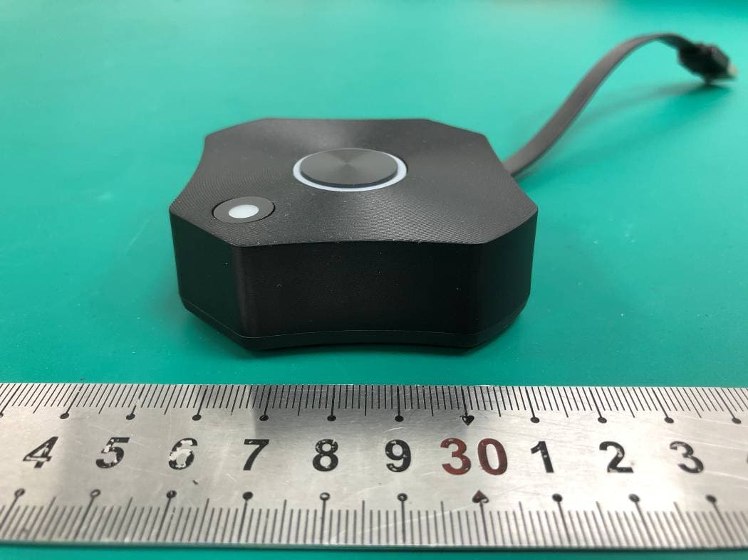
BY4WTR6000TX
Jul 28, 2021HD Wireless Conference System
Equipment Class
NII - Unlicensed National Information Infrastructure TX