BY4WTR6000TXHD Wireless Conference System
Trans Electric Co., Ltd.
Click to zoom
Application Details
- Equipment Class
- NII - Unlicensed National Information Infrastructure TX
- Date of Grant
- Jul 28, 2021
- Application Purpose
- Original Equipment
- Date of Application
- Jul 28, 2021
- Equipment Note
- HD Wireless Conference System
- Frequency Range
- 5755.00000000 - 5795.00000000
- Company
- Trans Electric Co., Ltd.
- Country
- Taiwan
Documents & Files
Document Text
Text extracted from the exhibit documents filed with the FCC. Open a document above to read the original.
Users Manual
1 HD Wireless Presentation System Model: WTR-6000 1080P Wireless HDMI Transmission INTRODUCTION Thank you for purchasing Trans WTR-6000 Wireless Presentation System. WTR-6000 is an ideal solution for Bring Your Own Device (BYOD) meeting. It supports multiple platforms including iOS, Android, Mac, and Windows operating systems for productive and flexible presentations and collaboration from individual devices. It also enables powerful 2 way split-screen sharing, making it useful and for ideas sharing and on-screen comparisons. A wireless connection to a shared display from participants’ seats will also remove the need for complex configuring and cabling. You can share BYOD content effortlessly with just one click in huddle rooms and many other types of meeting spaces FEATURES AND CONTENTS Features: Supports wireless transmission of HDMI up to 1080p 2-to-1 split-screen display at same time. Plug and Play-No App required, quick click to cast wirelessly Supports iOS、Android、MAC、Windows system for notebooks, tablets and smart phones. Wifi display support Wireless connectivity in up to 100ft (30 meters) (L.O.S) Up to 32 wireless transmitters with one receiver ( Additional TX required) Lantency : 200ms max. Package Contents: 1 x WTR-6000 Transmitter main unit 1 x WTR-6000 Receiver main unit 1x HDMI A-A cable 1x DC 5V/2A power adaptor User Manual 2 CONNECTION & OPERATION Transmitter Box Receiver Box Top I/O Descriptions LED Indication To p I/O Descriptions LED Indication HDMI In Main Button / LED Side Button / LED DC-in Reset USB Host RJ-45 HDMI Power Button 3 Transmitter LED Status Activate Host Standby w/o source input Main LED: OFF Host LED:Green ON Activate Guest Standby w/o source input Main LED: OFF Guest LED:Red ON Activate Host & in projecting Main LED:White ON Host LED:Green ON Host received request of projection Host LED: Green FLASH Guest standby w/o Projecting Main LED:Red ON Guest LED:Red ON Host standby w/o projecting Main LED:Red ON Host LED: Green ON Guest send request of projection and wait for allow Main LED:Red FLASH Guest LED:Red ON 1. Under connection 2. Pairing/TX OTA 3. Fail to connection (blinking over 1minutes) Activate Guest & in projecting Main LED:White ON Guest LED:Red ON Pairing done Main LED:White ON Host LED: OFF Transmitter OTA Completed Main LED:White FLASH Host LED: OFF Transmitter OTA Fail Main LED:Red FLASH Host LED: OFF 4 Installation Transmitter connection Step1: Use the HDMI A-A cable connect with WTR-6000 Transmitter and Source device (Laptop, Notebook) Step2: Connect the USB power cable of WTR-6000 Transmitter to the USB port of Notebook. Receiver connection Step3: Use HDMI cable to connect the HDMI OUT of WTR-6000 receiver to a display device (HDTV, Projector). Step4: Connect DC 5V/2A power adaptor to the Power Jack of WTR-6000 Receiver. Step5: Connection completed .When the receiver and transmitter are ready simply press the main button on the transmitter to mirror your device. Single click for mirror or disconnent. HDMI 5V 0.9A USB 3.0 HDMI Adapter Adapter HDMI 5 Note : The receiver and transmitter have finished the pairing setup before delivery. If no video signal on your display,. Please do the pairing Setup again by Plugging in transmitter’s USB cable to receiver USB port. (Follow the pairing instructions described in Pairing of TX and RX ) Additional Transmitter connection For second transmitter (optional) connection, please follow step 1 & 2. ‧For 2-to-1 split-screen display at same time. ‧Supports iOS、Android、MAC、Windows system for pc, notebooks, tablets and smart phones. Notice: If the HDMI cable is not long enough, please use extension cable to ensure the connection 6 Transmitter Operation Main Button (Mirror button) Host Guest Single click Mirror/Disconnect Send mirror request Hold for 3 seconds Full screen mirror send full screen mirror request Side button (control button ) Host Guest Single click Allow guest to mirror 一 Double click Deny request 一 Hold for 3 seconds Quit all display 一 Main Screen of RX When WTR-6000 TX is successfully turned on, the screen will be shown on display * Outbound link can select only one of W i-Fi and RJ45 wire line (LAN). PAIRING of TX & RX 1. When WTR-6000 TX is successfully turned on, the screen will be shown on display 2. Connect the end of the Transmitter USB-A cable to the USB port on the back of the Receiver, and it will automatically enter the Pairing mode 3. At this time, the display screen will display "Pairing..." Enter the automatic pairing connection, Sometime later display "Pairing OK". 7 Setup screen mirroring with mobile devices for receiver The receiver is connected to a screen or projector via HDMI for a wireless presentation. You can also cast your content via wifi display. Use your device's own built-in screen mirroring function. You do not require the WTR-6000 transmitter. Connect with WTR-6000 TX with SSID & Password directly. 1. SSID: Selecting the SSID WTR-6000 in the device’s Wi-Fi list 2. Password: Entering the password 12345678 to connect your device with WTR-6000 Receiver. Web Setting *WTR-6000 TX IP- when Devices (either laptops or mobile phones) connect with WTR-6000 TX with SSID & Password first, applying the IP in web browser can enter Admin setting page for more advance setting. 1. Preparation- To access the setting page, you have to choose either way to connect the devices. 1.1 Direct link- you can apply notebook or mobile phone to search WTR-6000 by wifi and key in relative SSID and Password. Turn on web browser and enter “192.168.168.1” in the address bar. 1.2 Through Wifi AP or Routers- if your WTR-6000 TX has been connected to a certain networking device, you can apply notebook or mobile phone to connect the same device. Turn on web browser and enter the address show in mainpage in the WTR-6000 IP shown below. After connecting to Tx and open the IP, please log in Admin for more advanced settings. WIFI D I S P L AY 8 2. Log in: If you are not logging…
Text truncated - open the document above for the full version.
Attestation Statements
Trans Electric Co., Ltd. ADD: 771, Sec. 2, Chungsan Road, Huatang, Changhua, Taiwan Email: [email protected] Tel: 886 4 763-3361Extension:210 Date: 2021-07-21 Dear Sir or Madam: The RF module, model RTL8821CU, installed in our product: HD Wireless Conference System, which supports Bluetooth, 2.4GHz/5GHz WiFi functions. But for marketing purpose, only 802.11 ac40 in 5150-5250GHz band was used in this product, all the other bands/functions have been shielded by manufacturer though software. Meanwhile, The product installed 2 antennas, but for marketing purpose, only ANT0 will enabled, the ANT1 has been disabled by manufacturer though software. We confirm that all information above is true, and we’ll be responsible for all the consequences. Please contact me if you have any question.
External Photos
Bay Area Compliance Laboratories Corp. (Shenzhen) Project No.: SZ4210526-19650E-RF Page 1 of 2 EXHIBIT B - EUT EXTERNAL PHOTOGRAPHS Bay Area Compliance Laboratories Corp. (Shenzhen) Project No.: SZ4210526-19650E-RF Page 2 of 2
ID Label/Location Info
Bay Area Compliance Laboratories Corp. (Shenzhen) Project No.: SZ4210526-19650E-RF EXHIBIT A - FCC ID LABEL AND LOCATION FCC ID Label FCC ID Label Location Information The label shown shall be permanently affixed at a conspicuous location on the device and be readily visible to the user at the time purchase (Labeling requirements per 2.925)
Internal Photos
Bay Area Compliance Laboratories Corp. (Shenzhen) Project No.: SZ4210526-19650E-RF Page 1 of 3 EXHIBIT C - EUT INTERNAL PHOTOGRAPHS Antenna Antenna has been disabled and will not use Bay Area Compliance Laboratories Corp. (Shenzhen) Project No.: SZ4210526-19650E-RF Page 2 of 3 Bay Area Compliance Laboratories Corp. (Shenzhen) Project No.: SZ4210526-19650E-RF Page 3 of 3
RF Exposure Info
Bay Area Compliance Laboratories Corp. (Shenzhen) Report No.: SZ4210526-19650E-00 FCC Part 15.407 Page 11 of 43 §1.1307 (b) (1) & §2.1091- MAXIMUM PERMISSIBLE EXPOSURE (MPE) Applicable Standard According to subpart 1.1307 (b)(1), 2.1091 systems operating under the provisions of this section shall be operated in a manner that ensures the public is not exposed to RF energy level in excess of the communication guidelines. Limits for General Population/Uncontrolled Exposure Limits for General Population/Uncontrolled Exposure Frequency Range (MHz) Electric Field Strength (V/m) Magnetic Field Strength (A/m) Power Density (mW/cm 2 ) Averaging Time (Minutes) 0.3-1.34 614 1.63 *(100) 30 1.34-30 824/f 2.19/f *(180/f 2 ) 30 30-300 27.5 0.073 0.2 30 300-1500 / / f/1500 30 1500-100,000 / / 1.0 30 f = frequency in MHz * = Plane-wave equivalent power density Result Calculated Formulary: Predication of MPE limit at a given distance S = 2 4R PG π S = power density (in appropriate units, e.g. mW/cm 2 ) P = power input to the antenna (in appropriate units, e.g., mW). G = power gain of the antenna in the direction of interest relative to an isotropic radiator, the power gain factor, is normally numeric gain. R = distance to the center of radiation of the antenna (appropriate units, e.g., cm) For worst case: Frequency (MHz) Antenna Gain Conducted Tune up Power Evaluation Distance (cm) Power Density (mW/cm 2 ) MPE Limit (mW/cm 2 ) (dBi) (numeric) (dBm) (mW) 5150-5250 0 1.0 12.0 15.85 20 0.0032 1.0 5725-5850 0 1.0 12.0 15.85 20 0.0032 1.0 To maintain compliance with the FCC’s RF exposure guidelines, place the equipment at least 20cm from nearby persons. Result: Compliance
Test Report
Note: This report may contain data that are not covered by the A2LA accreditation and are marked with an asterisk “★”. BACL is not responsible for the authenticity of any test data provided by the applicant. Data included from the applicant that may affect test results are marked with an asterisk ’*’. Customer model name, addresses, names, trademarks etc. are not considered data. This report cannot be reproduced except in full, without prior written approval of the Company. Unless otherwise stated the results shown in this test report refer only to the sample(s) tested. This report is valid only with a valid digital signature. The digital signature may be available only under the Adobe software above version 7.0. FCC PART 15.407 TEST REPORT For Trans Electric Co., Ltd. 771 Sec.2 Chungsan Rd, Huatang, Changhua, Taiwan FCC ID: BY4WTR6000TX Report Type: Original Report Product Type: HD Wireless Conference System Re port Number: SZ4210526-19650E-00 Re port Date: 2021-07-07 Reviewed B y: Jacob Kong RF En gineer Prepared By: Bay Area Compliance Laboratories Corp. (Shenzhen) 5F(B-West) , 6F, 7F, the 3rd Phase of Wan Li Industrial Building D, Shihua Rd, FuTian Free Trade Zone, Shenzhen, China Tel: +86-755-33320018 Fax: +86-755-33320008 www.baclcorp.com.cn Bay Area Compliance Laboratories Corp. (Shenzhen) Report No.: SZ4210526-19650E-00 FCC Part 15.407 Page 2 of 43 TABLE OF CONTENTS GENERAL INFORMATION ....................................................................................................................................... 4 PRODUCT DESCRIPTION FOR EQUIPMENT UNDER TEST (EUT) ..................................................................................... 4 OBJECTIVE ................................................................................................................................................................... 4 TEST METHODOLOGY .................................................................................................................................................. 4 MEASUREMENT UNCERTAINTY .................................................................................................................................... 5 TEST FACILITY ............................................................................................................................................................. 5 SYSTEM TEST CONFIGURATION .......................................................................................................................... 6 DESCRIPTION OF TEST CONFIGURATION ...................................................................................................................... 6 EUT EXERCISE SOFTWARE .......................................................................................................................................... 6 DUTY CYCLE ................................................................................................................................................................ 6 EQUIPMENT MODIFICATIONS ....................................................................................................................................... 6 SUPPORT EQUIPMENT LIST AND DETAILS .................................................................................................................... 7 EXTERNAL I/O CABLE .................................................................................................................................................. 7 BLOCK DIAGRAM OF TEST SETUP ................................................................................................................................ 7 SUMMARY OF TEST RESULTS ............................................................................................................................... 8 TEST EQUIPMENT LIST ........................................................................................................................................... 9 §1.1307 (b) (1) & §2.1091- MAXIMUM PERMISSIBLE EXPOSURE (MPE) .......................................................... 11 APPLICABLE STANDARD ............................................................................................................................................ 11 RESULT ...................................................................................................................................................................... 11 FCC §15.203 – ANTENNA REQUIREMENT .......................................................................................................... 12 APPLICABLE STANDARD ............................................................................................................................................ 12 ANTENNA CONNECTOR CONSTRUCTION .................................................................................................................... 12 FCC §15.407 (b) (9) §15.207 (a) – CONDUCTED EMISSIONS ............................................................................. 13 APPLICABLE STANDARD ............................................................................................................................................ 13 EUT SETUP ................................................................................................................................................................ 13 EMI TEST RECEIVER SETUP ....................................................................................................................................... 13 TEST PROCEDURE ...................................................................................................................................................... 13 TEST DATA ................................................................................................................................................................ 14 §15.205 & §15.209 & §15.407(B) (1), (4), (9), (10) – UNDESIRABLE EMISSION ............................................... 17 A…
Text truncated - open the document above for the full version.
Test Setup Photos
Bay Area Compliance Laboratories Corp. (Shenzhen) Project No.: SZ4210526-19650E-RF Page 1 of 2 EXHIBIT D - TEST SETUP PHOTOGRAPHS Conducted Emissions - Front View Conducted Emissions - Side View Bay Area Compliance Laboratories Corp. (Shenzhen) Project No.: SZ4210526-19650E-RF Page 2 of 2 Radiated Emissions – Front View (Below 1 GHz) Radiated Emissions View (Above 1 GHz)
Contact Information
Applicant
Grace Wang(Vice-General Manager, Intel' sales Dept.)
Test Firm
Bay Area Compliance Laboratories Corp. (Shenzhen)Well Wang
[email protected]+86 (0) 755 33320018
Technical Specifications
| # | Rule Parts | Frequency Range | Power Output |
|---|---|---|---|
| 2 | 15E | 5.75 GHz - 5.79 GHz | 14.00 mW |
Other Applications from Trans Electric Co., Ltd.
BY4WTR1500C
Sep 18, 2024Wireless HD Transmitter & Receiver Kit
Equipment Class
NII - Unlicensed National Information Infrastructure TX
BY4BRX5200A
Sep 25, 2022Portable Bluetooth Wireless Transmitter & Receiver
Equipment Class
DSS - Part 15 Spread Spectrum Transmitter
BY4WFD5000PRO
Jan 17, 20224K UHD Wireless Presentation Receiver
Equipment Class
DTS - Digital Transmission System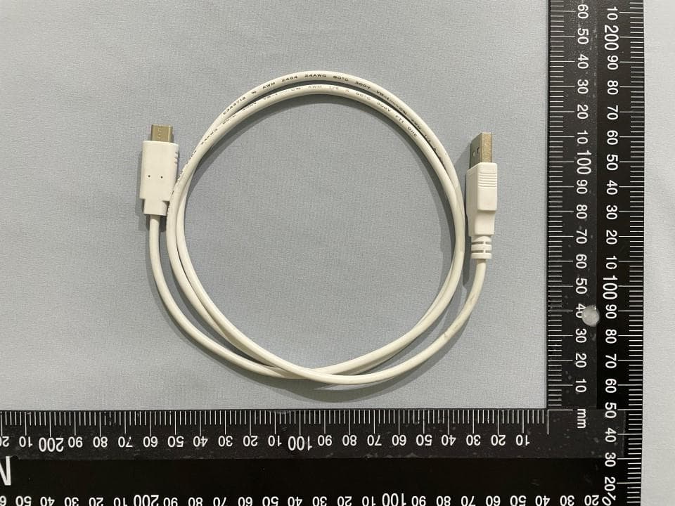
BY4WFD1500PRO
Jan 17, 2022Full-HD Wireless Presentation Receiver
Equipment Class
DTS - Digital Transmission System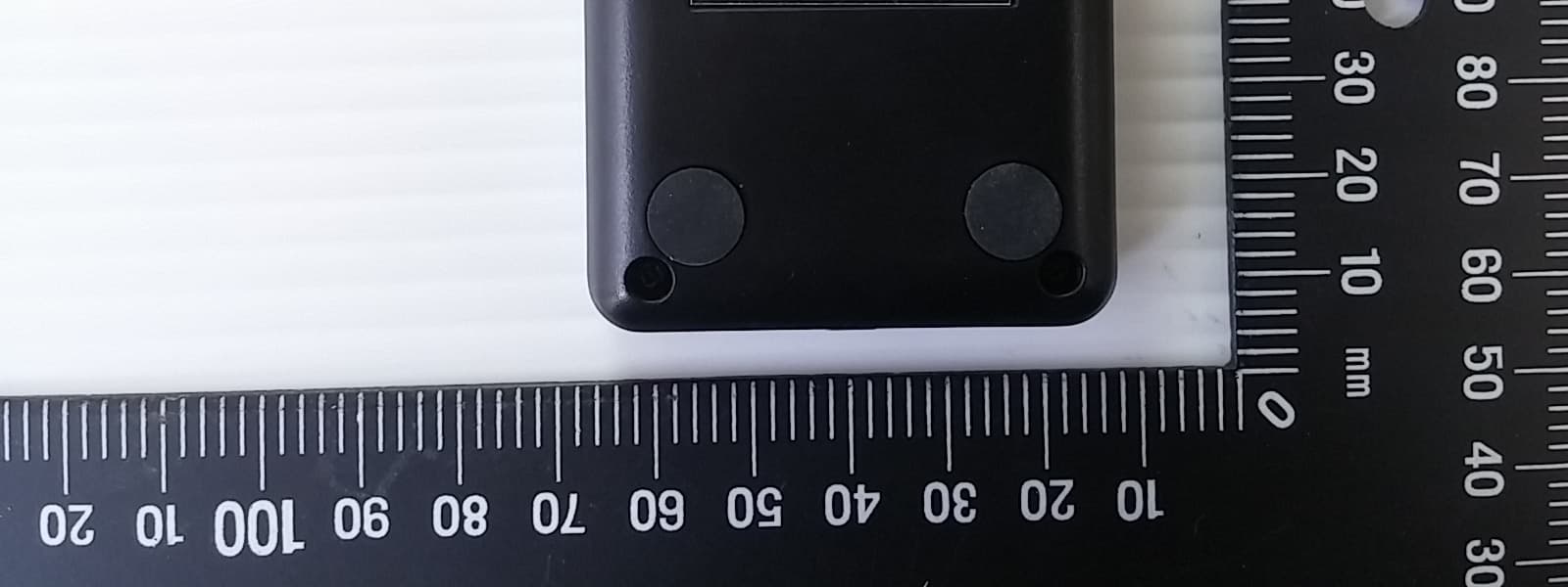
BY4WTR1000
Nov 15, 20151080P HD wireless sender
Equipment Class
NII - Unlicensed National Information Infrastructure TX