BY4DAS3002.4GHz USB Connection Digital Audio Link
Trans Electric Co., Ltd.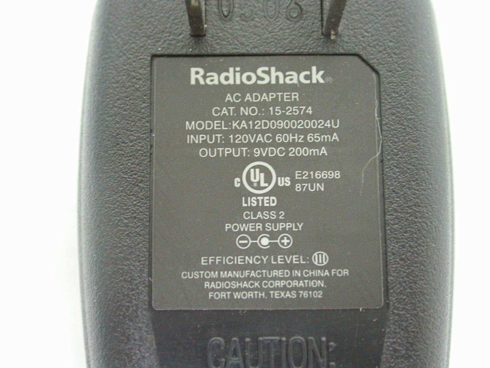
Click to zoom
Application Details
- Equipment Class
- DTS - Digital Transmission System
- Date of Grant
- Jul 30, 2006
- Application Purpose
- Original Equipment
- Date of Application
- Jul 30, 2006
- Equipment Note
- 2.4GHz USB Connection Digital Audio Link
- Frequency Range
- 2410.00000000 - 2473.00000000
- Company
- Trans Electric Co., Ltd.
- Country
- Taiwan
Documents & Files
Document Text
Text extracted from the exhibit documents filed with the FCC. Open a document above to read the original.
Users Manual
Thank you for purchasing your 2.4 GHz USB Connection Digital Audio Link from RadioShack. From now on you can listen to your music library from your computer, iPod, MP3, or CD player through a stereo system or other audio source in your house. 15-2574 2.4 GHz USB Connection Digital Audio Link • Keep your ditial audio link dry and clean. If it gets wet or dirty, wipe it dry or clean immediately. • Wipe your digital audio link with a damp cloth occasionally to keep it looking new. • Use and store your digital audio link in room temperature environments only. • Modifying or tampering the 2.4 GHz digital audio link’s internal components can cause malfunction and might invalidate its warranty. If your 2.4 GHz audio link is not performing as it should, take it to your local RadioShack store for assistance. care and service This equipment has been tested and found to comply with the limits for a Class B digital device, pursuant to part 15 of the FCC Rules. These limits are designed to provide reasonable protection against harmful interference in a residential installation. This equipment generates, uses and can radiate radio frequency energy and, if not installed and used in accordance with the instructions, may cause harmful interference to radio communications. However, there is no guarantee that interference will not occur in a particular installation. If this equipment does cause harmful interference to radio or television reception, which can be determined by turning the equipment off and on, the user is encouraged to try to correct the interference by one or more of the following measures: • Reorient or relocate the receiving antenna. • Increase the separation between the equipment and receiver. • Connect the equipment into an outlet on a circuit different from that to which the receiver is connected. • Consult your local RadioShack store or an experienced radio/TV technician for help. If you cannot eliminate the interference, the FCC requires that you stop using your product. Changes or modifications not expressly approved by RadioShack may cause interference and void the user’s authority to operate the equipment. This device complies with Part 15 of the FCC Rules. Operation is subject to the following two conditions: (1) this device may not cause harmful interference, and (2) this device must accept any interference received, including interference that may cause undesired operation. rf emissions information Product 2.4 GHz USB Connection Digital Audio Link Model15-2574 Responsible Party RadioShack 300 RadioShack Circle Fort Worth,TX 76102 Phone817-415-3200 Frequency Range ...................................................... 2.4 ~ 2.4835 GHz Channel Frequency ........................................ 2410, 2419 ~ 2473 MHz Channel Spacing ......................................................................... 9 MHz Frequency Stability ................................................................... ±1 MHz Transmission Range .......................... 45 ft (15 m, in the home) (Max.)............... 45 ft (15 m, in the home) (Max.)......... 45 ft (15 m, in the home) (Max.).... 45 ft (15 m, in the home) (Max.)... 45 ft (15 m, in the home) (Max.)45 ft (15 m, in the home) (Max.) (15 m, in the home) (Max.)15 m, in the home) (Max.), in the home) (Max.) ......................................................... 100 ft (30.5 m, line of sight) (Max.) 100 ft (30.5 m, line of sight) (Max.)100 ft (30.5 m, line of sight) (Max.)(30.5 m, line of sight) (Max.)30.5 m, line of sight) (Max.), line of sight) (Max.) Operating Temperature ............................. 3232°F to 104°F (0 (00°C to 40°C)) Power Supply ..........................................120VAC/60Hz, 9V DC/200mA Response .................................................................... 20 ~ 20kHz±3dB S/N Ratio ............................................................................. 40dB (Min.) Transmitter Modulation Type ......................................................... FSK Modulation Power .............................................................10 dBm for FCC (Typical).........................................................10 dBm for FCC (Typical)..........................................10 dBm for FCC (Typical) Input Impedance ................................................. >10K Ohm (3.5 mm) Input Level ....................................................................... 2 Vms (Max.) Dimensions (H x W x D) ....................................... 3⅜ x 3⅜ x 1¼ Inch .................................................................................... (86 x86 x 32 mm) Weight ...............................................................................2.47 oz (70 g)...............................................................................2.47 oz (70 g) Receiver Sensitivity ..................................................................... −85 dBm (Min.) Output Impedance .............................................. >10K Ohm (3.5 mm) Output Level ...................................................................... 2 Vms±10% Dimensions (H x W x D) ....................................... 3⅜ x 3⅜ x 1¼ Inch .................................................................................... (86 x86 x 32 mm) Weight ...............................................................................2.29 oz (65 g) Specifications are typical; individual units might vary. Specifications are subject to change and improvement without notice. Actual product may vary from the images found in this document. specifications This product is warranted by RadioShack against manufacturing defects in material and workmanship under normal use for ninety (90) days from the date of purchase from RadioShack company-owned stores and authorized RadioShack franchisees and dealers. For complete warranty details and exclusions, check with your local RadioShack store. RadioShack Customer Relations 300 RadioShack Circle, Fort Worth, TX 761…
Text truncated - open the document above for the full version.
Cover Letter(s)
1 Helen Zhao Subject: FW: Trans Electric Co Ltd, FCC ID: BY4DAS300, Assessment NO.: AN06T6014, Notice#1 ID Label_Location.pdf 06-07-MAS-016-01 _Test Report_0... From: hsieh Sent: Monday, July 31, 2006 2:06 AM To: Helen Zhao Subject: Re: Trans Electric Co Ltd, FCC ID: BY4DAS300, Assessment NO.: AN06T6014, Notice#1 Dear Helen, Thank you for your mail. Re-Q#1: Attached please find the new FCC ID label. The FCC DoC Logo has been added on the label. Re-Q#2: Attached please find the revise report. We add the AV limit information at the report. Best regards, Joe -----Original Message----- Sent: Friday, July 28, 2006 3:04 PM Subject: Trans Electric Co Ltd, FCC ID: BY4DAS300, Assessment NO.: AN06T6014, Notice#1 Question #1: This device is a PC peripheral, if the digital is authorized through DoC, please add FCC DoC logo on the FCC ID label; if it is authorized throught certification, please submit a separate filing under equipment class of "JBP". Question #2: Test report section 4.3 - it indicates "if QP value is under AVG limit, so AVG value does not need to be measured". In the following tables, please change from QP limit to AVG limit, also please update the margin. 2 Best Regards, Helen Zhao The items indicated above must be submitted before processing can continue on the above referenced application. Failure to provide the requested information within 30 days of the original e-mail date may result in application dismissal and forfeiture of the filing fee. Also, please note that partial responses increase processing time and should not be submitted. Any questions about the content of this correspondence should be directed to the e-mail address listed below the name of the sender.
External Photos
ETC Report No.: 06-07-MAS-016-01 Page A1 of A2 FCC ID. :BY4DAS330 ANNEX A: EXTERNAL CONSTRUCTION PHOTOS OF EUT 1. Outside view 1 of EUT 2. Outside view 2 of EUT ETC Report No.: 06-07-MAS-016-01 Page A2 of A2 FCC ID. :BY4DAS330 3. Adaptor
ID Label/Location Info
ID Label / Location
Internal Photos
ETC Report No.: 06-07-MAS-016-01 Page B1 of B3 FCC ID. :BY4DAS330 ANNEX B: INTERNAL CONSTRUCTION PHOTOS OF EUT 1. Inside View of EUT 2. Front view of PCB1 ETC Report No.: 06-07-MAS-016-01 Page B2 of B3 FCC ID. :BY4DAS330 3. Rear view of PCB1 4. Front view of PCB2 ETC Report No.: 06-07-MAS-016-01 Page B3 of B3 FCC ID. :BY4DAS330 5. Rear view of PCB2 6. Rear view of PCB2
Test Report
ETC Report No. : 06-07-MAS-016-01 Sheet 1 of 53 Sheets FCC ID. :BY4DAS300 Rev. No 1.0 CONFORMANCE TEST REPORT FOR FCC 47 CFR, Part 15 Subpart C Report No.: 06-07-MAS-016-01 Client: TRANS ELECTRIC CO., LTD. Product: 2.4GHz USB Connection Digital Audio Link Model: DAS-300 FCC ID: BY4DAS300 Manufacturer/supplier: TRANS ELECTRIC CO., LTD. Date test item received: 2006/07/04 Date test campaign completed: 2006/07/20 Date of issue: 2006/07/25 The test result only corresponds to the tested sample. It is not permitted to copy this report, in part or in full, without the permission of the test laboratory. Total number of pages of this test report: 53 pages Total number of pages of photos: External photos 2 pages Internal photos 3 pages Setup photos 2 pages Test Engineer Checked By Approved By Mark James Joe Hsieh ELECTRONICS TESTING CENTER, TAIWAN NO.8, LANE 29, WENMING RD., LESHAN TSUEN, GUISHAN SHIANG, TAOYUAN COUNTY, TAIWAN 33383, R.O.C. TEL: (03) 3276170~4 INT: +886-3-3276170~4 FAX: (03) 3276188 INT: +886-3-3276188 ETC Report No. : 06-07-MAS-016-01 Sheet 2 of 53 Sheets FCC ID. :BY4DAS300 Rev. No 1.0 Client : TRANS ELECTRIC CO., LTD. Address : 765, Sec.2, Chungsan Rd., Huatang, Changhua, Taiwan, R.O.C. Manufacturer : TRANS ELECTRIC CO., LTD. Address : 765, Sec.2, Chungsan Rd., Huatang, Changhua, Taiwan, R.O.C. EUT : 2.4GHz USB Connection Digital Audio Link Trade name : Trans Model No. : DAS-300 Power Source : Adapter : RadioShack / KA12D090020024U Input: 120Vac, 60Hz, 65mA Output: DC 9VDC, 200mA Regulations applied : FCC 47 CFR, Part 15 Subpart C (2006) The testing described in this report has been carried out to the best of our knowledge and ability, and our responsibility is limited to the exercise of reasonable care. This certification is not intended to believe the sellers from their legal and/or contractual obligations. The compliance test is only certified for the test equipment and the results of the testing report relate only to the item tested. The compliance test of this report was conducted in accordance with the appropriate standards. It’s not intention to assure the quality and performance of the product. This report shall not be reproduced except in full, without the approval of ETC. This report must not be used by the client to claim product endorsement by NVLAP or any agency of the U.S. Government. Laboratory Introduction: Electronics Testing Center, Taiwan is recognized, filed and mutual recognition arrangement as following: 1 ISO9001: TüV Product Service 2 ISO/IEC 17025: BSMI, CNLA, DGT, NVLAP, CCIBLAC, UL, Compliance 3 Filing: FCC, Industry Canada, VCCI 4 MRA: Australia, Hong Kong, New Zealand, Singapore, USA, Japan, Korea, China, APLAC through CNLA 5 FCC Registration Number: 90588, 91094, 91095 NVLAP Lab Code 200133-0 ETC Report No. : 06-07-MAS-016-01 Sheet 3 of 53 Sheets FCC ID. :BY4DAS300 Rev. No 1.0 Table of Contents Page 1 GENERAL INFORMATION .............................................................................................................. 5 1.1 Product Description..............................................................................................................................5 1.2 Characteristics of Device .....................................................................................................................5 1.3 Test Methodology................................................................................................................................5 1.4 Test Facility..........................................................................................................................................5 2 PROVISIONS APPLICABLE ............................................................................................................. 6 2.1 Definition.............................................................................................................................................6 2.2 Requirement for Compliance...............................................................................................................7 2.3 Restricted Bands of Operation.............................................................................................................9 2.4 Labeling Requirement..........................................................................................................................9 2.5 User Information................................................................................................................................10 3. SYSTEM TEST CONFIGURATION ............................................................................................... 11 3.1 Devices for Tested System.................................................................................................................11 4 CONDUCTED EMISSION MEASUREMENT............................................................................... 12 4.1 Standard Applicable...........................................................................................................................12 4.2 Measurement Procedure.....................................................................................................................12 4.3 Conducted Emission Data..................................................................................................................13 4.4 Result Data Calculation......................................................................................................................19 4.5 Conducted Measurement Equipment.................................................................................................19 5 ANTENNA REQUIREMENT ........................................................................................................... 20 5.1 Standard Applicable...........................................................................................................................20 5.2 Antenna Construction and Directional Gain.....................................................…
Text truncated - open the document above for the full version.
Test Report
ETC Report No. : 06-07-MAS-016-01 Sheet 36 of 53 Sheets FCC ID. :BY4DAS300 Rev. No 1.0 9 SPURIOUS EMISSION - RF CONDUCTED MEASUREMENT 9.1 Standard Applicable According to 12.247 (c) , in any 100 kHz bandwidth outside the frequency band in which the spread spectrum or digitally modulated intentional radiator is operating, the radio frequency power that is produced by the intentional radiator shall be at least 20 dB below that in the 100 kHz bandwidth within the band that contains the highest level of the desired power, based on either an RF conducted or a radiated measurement. Attenuation below the general limits specified in Section 15.209(a) is not required. In addition, radiated emissions which fall in the restricted bands, as defined in Section 15.205(a), must also comply with the radiated emission limits specified in Section 15.209(a) (see Section 15.205(c)). 9.2 Measurement Procedure 1. Check the calibration of the measuring instrument using either an internal calibrator or a known signal from an external generator. 2. Position the EUT as shown in figure 2. Turn on the EUT and connect its antenna terminal to measurement instrument via a low loss cable. Then set it to any one measured frequency within its operating range and make sure the instrument is operated in its linear range. 3. Set both RBW and VBW of spectrum analyzer to 100 kHz with a convenient frequency span including 100kHz bandwidth from band edge. 4. Measure the highest amplitude appearing on spectral display and set it as a reference level. Plot the graph with marking the highest point and edge frequency. 5. Repeat above procedures until all measured frequencies were complete. 9.3 Measurement Equipment Equipment Manufacturer Model No. Next Cal. Due Spectrum Analyzer Hewlett-Packard 8564EC 09/23/2006 ETC Report No. : 06-07-MAS-016-01 Sheet 37 of 53 Sheets FCC ID. :BY4DAS300 Rev. No 1.0 9.4 Measurement Data Test Date: Jul. 19, 2006 Temperature: 22 °C Humidity: 68% Channel Frequency(MHz) Chart 1 2410 Page 38, Page 40 5 2446 Page 41 8 2473 Page 39, Page 42 All out-of –band conducted emissions were more than 20dB below the carrier. Note: Please refer to page 38 to page 42 for chart ETC Report No. : 06-07-MAS-016-01 Sheet 38 of 53 Sheets FCC ID. :BY4DAS300 Rev. No 1.0 ETC Report No. : 06-07-MAS-016-01 Sheet 39 of 53 Sheets FCC ID. :BY4DAS300 Rev. No 1.0 ETC Report No. : 06-07-MAS-016-01 Sheet 40 of 53 Sheets FCC ID. :BY4DAS300 Rev. No 1.0 ETC Report No. : 06-07-MAS-016-01 Sheet 41 of 53 Sheets FCC ID. :BY4DAS300 Rev. No 1.0 ETC Report No. : 06-07-MAS-016-01 Sheet 42 of 53 Sheets FCC ID. :BY4DAS300 Rev. No 1.0 ETC Report No. : 06-07-MAS-016-01 Sheet 43 of 53 Sheets FCC ID. :BY4DAS300 Rev. No 1.0 10 RADIATED EMISSION MEASUREMENT 10.1 Standard Applicable For unintentional radiator, the radiated emission shall comply with § 15.109(a). For intentional radiators, according to § 15.247 (a), operation under this provision is limited to frequency hopping and direct sequence spread spectrum, and the out band emission shall be comply with § 15.247 (c) 10.2 Measurement Procedure 1. Setup the configuration per figure 3 and 4 for frequencies measured below and above 1 GHz respectively. 2. For emission frequencies measured below 1 GHz, it is performed in a semi-anechoic chamber to determine the accurate frequencies of higher emissions. For emission frequencies measured above 1 GHz, a pre-scan be performed with a 1 meter measuring distance before final test. 3. For emission frequencies measured below and above 1 GHz, set the spectrum analyzer on a 120 kHz and 1 MHz resolution bandwidth respectively for each frequency measured in step 2. 4. The search antenna is to be raised and lowered over a range from 1 to 4 meters in horizontally polarized orientation. Position the highness when the highest value is indicated on spectrum analyzer, then change the orientation of EUT on test table over a range from 0 。 to 360 。 with a speed as slow as possible, and keep the azimuth that highest emission is indicated on the spectrum analyzer. Vary the antenna position again and record the highest value as a final reading. A RF test receiver is also used to confirm emissions measured. Note : A filter was used to avoid pre-amplifier saturated when measure TX operation mode. 5. Repeat step 4 until all frequencies need to be measured were complete. 6. Repeat step 5 with search antenna in vertical polarized orientations. 7. Check the three frequencies of highest emission with varying the datarate, placement of ANT. cables associated with EUT to obtain the worse case and record the result. ETC Report No. : 06-07-MAS-016-01 Sheet 44 of 53 Sheets FCC ID. :BY4DAS300 Rev. No 1.0 Figure 3 : Frequencies measured below 1 GHz configuration RF Test Receiver Search Antenna 3m 4m 1m Turn Table EUT 0.8m Antenna Tower Ground Plane Figure 4 : Frequencies measured above 1 GHz configuration Spectrum Analyzer Horn Antenna 3m 4m 1m Turn Table EUT 0.8m Antenna Tower Amplifier ETC Report No. : 06-07-MAS-016-01 Sheet 45 of 53 Sheets FCC ID. :BY4DAS300 Rev. No 1.0 10.3 Measuring Instrument The following instrument are used for radiated emissions measurement : Equipment Manufacturer Model No. Next Cal. Due EMI Test Receiver Hewlett-Packard 8546A 12/12/2006 Spectrum Analyzer Rohde & Schwarz FSU46 11/02/2006 Horn Antenna EMCO 3115 06/06/2007 Horn Antenna EMCO 3116 07/21/2006 Preamplifier Hewlett-Packard 8449B 09/19/2006 BiLog Antenna Schaffner CBL 6112B 06/11/2007 Spectrum Analyzer Hewlett-Packard 8564EC 09/23/2006 Measuring instrument setup in measured frequency band when specified detector function is used : Frequency Band (MHz) Instrument Function Resolution bandwidth Video Bandwidth RF Test Receiver Quasi-Peak 120 kHz 300 kHz 30 to 1000 Spectrum Analyzer Peak 120 kHz 300 kHz Spectrum Analyzer Peak 1 MHz 1 MHz Above 1000 Spectrum Analyzer Average 1 MHz 10 Hz Measuring instrument setup in measured frequency band when specified detector function is used: Frequency Band (MHz) Instrument …
Text truncated - open the document above for the full version.
Test Setup Photos
ETC Report No. : 06-07-MAS-016-01 Sheet 1 of 2 Sheets FCC ID. :BY4DAS330 Photos of Radiation Measuring Setup ETC Report No. : 06-07-MAS-016-01 Sheet 2 of 2 Sheets FCC ID. :BY4DAS330 Photos of Conduction Measuring Setup
Contact Information
Applicant
Grace Wang(Vice-General Manager, Intel' sales Dept.)
Test Firm
Electronics Testing Center, TaiwanWin-Po Tsai
Technical Specifications
| # | Rule Parts | Frequency Range | Power Output |
|---|---|---|---|
| 1 | 15C | 2.41 GHz - 2.47 GHz | 5.21 mW |
Other Applications from Trans Electric Co., Ltd.
BY4WTR1500C
Sep 18, 2024Wireless HD Transmitter & Receiver Kit
Equipment Class
NII - Unlicensed National Information Infrastructure TX
BY4BRX5200A
Sep 25, 2022Portable Bluetooth Wireless Transmitter & Receiver
Equipment Class
DSS - Part 15 Spread Spectrum Transmitter
BY4WFD5000PRO
Jan 17, 20224K UHD Wireless Presentation Receiver
Equipment Class
DTS - Digital Transmission System
BY4WFD1500PRO
Jan 17, 2022Full-HD Wireless Presentation Receiver
Equipment Class
DTS - Digital Transmission System
BY4WTR6000TX
Jul 28, 2021HD Wireless Conference System
Equipment Class
NII - Unlicensed National Information Infrastructure TX