BY4IR100ARemote Control Extender
Trans Electric Co., Ltd.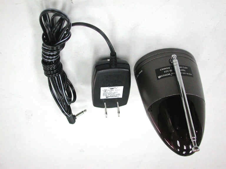
Click to zoom
Application Details
- Equipment Class
- DSC - Part 15 Security/Remote Control Transmitter
- Date of Grant
- Feb 28, 2002
- Application Purpose
- Original Equipment
- Date of Application
- Feb 28, 2002
- Equipment Note
- Remote Control Extender
- Frequency Range
- 418.00000000 - 418.00000000
- Company
- Trans Electric Co., Ltd.
- Country
- Taiwan
Documents & Files
Document Text
Text extracted from the exhibit documents filed with the FCC. Open a document above to read the original.
Users Manual
REMOTE CONTROL EXTENDER DSC-IR100A USER MANUAL Product Description Applications The Remote operation of electronics products that utilize IR (Infrared) remote control technology such as: The DSC-IR100A Wireless Infrared Remote Control Extender enables you to extend their range of your present Infrared IR Remote Control so that you can operate VCRs, stereos, Cable Converter, Satellite receivers, etc. Virtually any where within your home. Unlike ordinary remote controls which are only effective in close range. " line of sight" use, The DSC-IR100A uses radio frequencies and can operate through walls, doors, around corners, etc. Television VCR's (Video Cassette Recorders) CDs (Compact Disc) DVD's (Digital Video Disc) LDP's (Laser Disc Players) Cable Converter Boxes Satellite Receivers Audio / Hi-Fi Stereo Systems Wireless Video Sender Systems Any (IR) Remote Controlled Devices Installation Transmitter: Receiver / Probe: You will be using your normal IR remote control and "aiming" it at DSC- IR100A IR extender transmitter. 1. Plug the supplied AC adapter into any standard electrical wall outlet. 2. Connect the other end of the AC adapter cable in the"power in" socket located on the side of your transmitter unit. 3. Place the transmitter in the remote location so that it is in the line of sight of the position where you are located (couch, chair, bed, etc.) so that you can "aim" your remote control at the transmitter. 1. Plug the supplied AC adapter into any standard electrical wall outlet. 2. Connect the other end of the AC adapter cable into the "power in" socket located on the side of the receiver unit. 3. Place the DSC-IR100A receiver in a high, line-of-sight position facing in front of the electronic device you are going to control. Be certain that there are no obstructions between the DSC-IR100A receiver and the infrared 4. In situation where it is not possible or convenient to place the DSC-IR 100A a high location, or near the equipment being controlled, and have the receiving window of the Plug one end of the probe cable into the jack located on the side of the DSC-IR100A receiver. Attach the other end of the probe to the IR receiving attached to the probe. receiving window of the equipment. receiver in line-of-sight of the controlled equipment, a remote probe is supplied. The remote probe enables you to place the DSC-IR100A receiver in probe transmit the IR data directly to the IR equipment. window of the equipment being controlled using to double stick tape INSTALLATION DIAGRAM B. Stereo System with remote Probe: A. Stereo System: D. VCR / TV /Wireless Video System with remote Probe: C. VCR / TV /Wireless Video System: Care and Maintenance Keep the DSC-IR100A Remote Extender dry. If it gets wet, wipe it dry immediately. Use and store the DSC-IR100A only in normal temperature environm ents.Extreme temperature can shorten the life of electronic devices Handle the DSC-IR100A gently and carefully. Dropping it can damage the circuit board anc can cause it to work improperly. Keep the DSC-IR100A away from dust and dirt, which can cause wear of parts. Wipe the DSC-IR100A with a damp cloth occasionally to keep it Do not use harsh chemicals, cleaning solvents, or strong detergents. premature looking new. Specifications Operating Voltage .......................................105-130 VAC, 60Hz Power Consumption (pair)............................4 Watts Max Transmission Frequency...............................418 MHz + / - 1 MHz User Informaton This device complies with part 15 of the FCC Rules. Operation is subject to the following two conditions: (1) This device may not cause harmful interference, and (2) this device must accept any interference received, including interference that may cause undesired operation. Caution: The changes or modifications not expressly approved by the party responsible for compliance could void the user’s authority to operate the equipment.
Block Diagram
1234 A B C D 4321 D C B A IR DETECTOR LPF AND DRIVER ASK MODULATOR RF OSCILLATOR ANTENNA IR SENSOR REGULATORREGULATOR DC POWER +5V+10V +12V BLOCK DIAGRAM OF DSC IR100A
Operational Description
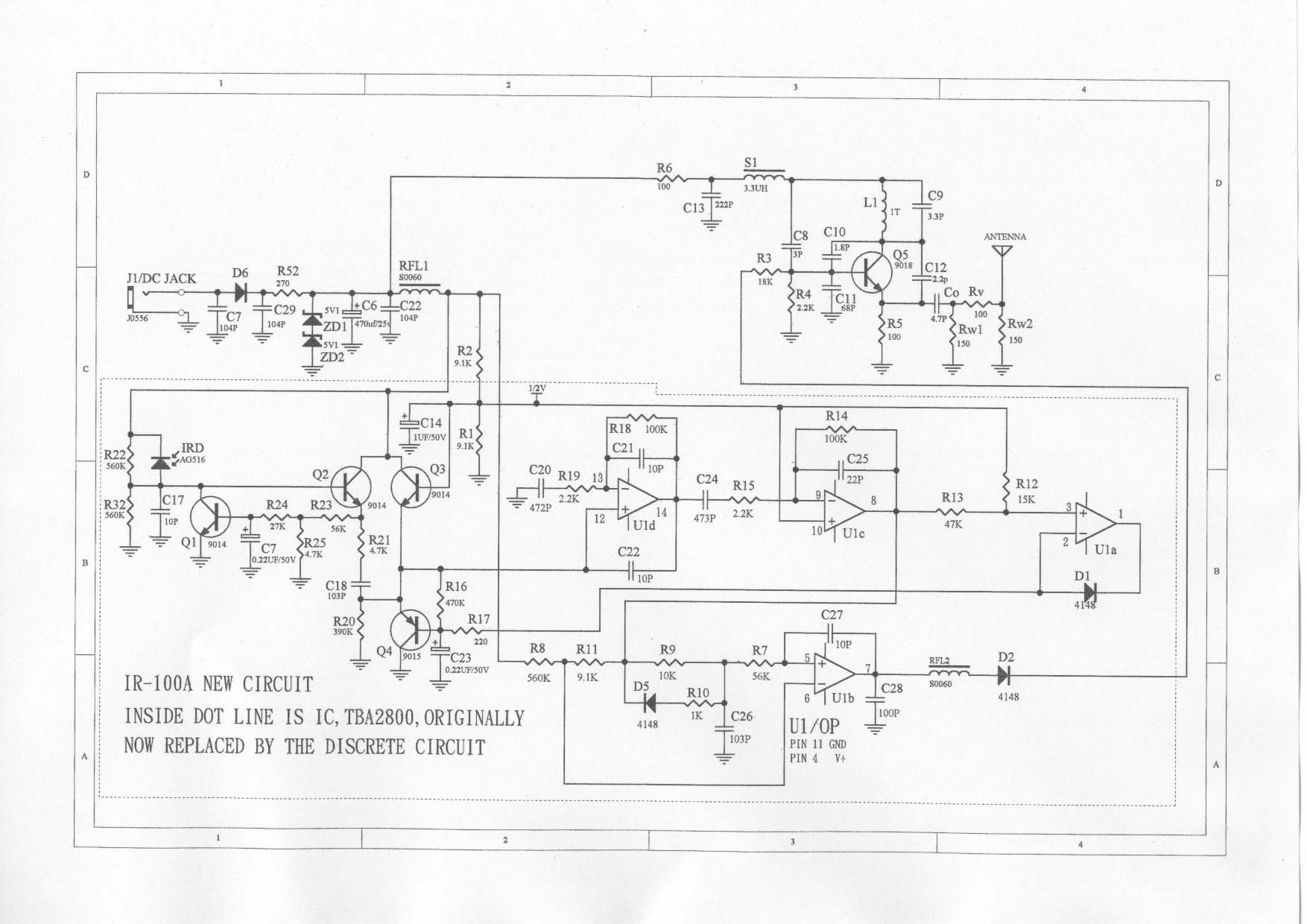
IR100A Working Principals IR; infrared ray; remote controller is spread used at family house, unfortunately IR natural is working under line of sight, So IR remote controller is no way to work properly room by room due to space shielding by wall. Including carrier and coding, IR remote control signal detected by IR sensor, then the sensor transfers current to voltage and amplified by the following booster circuit. The colpitts LC oscillator resonate at 418MHz; trigger to oscillate is controlled by boosted IR signal. In other words, via the ASK; Amplitude Shift Keying; modulation, IR signal was carried on the 418MHz radio. Using the basic regenerative receiver to recover the modulated IR signal, which drives IR- LED to duplicate IR remote control signal.
Test Report
FCC ID.: BY4IR100A Rev. No 1.0 FCC Part 15 Subpart C EMI TEST REPORT of E.U.T. : Remote Control Extender(Transmitter) FCC ID. : BY4IR100A MODEL : DSC-IR100A Working Frequency : 418MHz for APPLICANT: Trans Electric Co., Ltd. ADDRESS: 765 Chungsan Road, Section 2, Huatang, Changhua, TAIWAN Test Performed by ELECTRONICS TESTING CENTER, TAIWAN NO. 8 LANE 29, WENMIMG ROAD, LOSHAN TSUN, KWEISHAN HSIANG, TAOYUAN, TAIWAN, R.O.C. Tel:(03)3276170-3276174 Fax:(03)3276188 Report Number : ET91S-01-188 ETC Report No.:ET91S-01-188FCC ID.: BY4IR100A Rev. No 1.0 TEST REPORT CERTIFICATION Applicant: Trans Electric Co., Ltd. 765 Chungsan Road, Section 2, Huatang, Changhua, TAIWAN Manufacturer: Trans Electric Co., Ltd. 765 Chungsan Road, Section 2, Huatang, Changhua, TAIWAN Description of EUT: a) Type of EUT: Remote Control Extender(Transmitter) b) Trade Name: RECOTON c) Model No.: DSC-IR100A d) FCC ID: BY4IR100A e) Working Frequency: 418MHz f) Power Supply: AC120V/60Hz g) Adapter: I/P AC 120V/60Hz O/P DC 12V, 100mA Regulation Applied: FCC Rules and Regulations Part 15 Subpart C (1999) I HEREBY CERTIFY THAT; The data shown in this report were made in accordance with the procedures given in ANSI C63.4 and the energy emitted by the device was founded to be within the limits applicable. I assume full responsibility for accuracy and completeness of these data. Note : 1. The results of the testing report relate only to the items tested. 2. The testing report shall not be reproduced except in full, without the written approval of ETC. Test Date : Jan. 30, 2002 Test Engineer : Approve & Authorized Signer : Win-Po Tsai, Supervisor, NVLAP Signatory EMC Dept. I of ELECTRONICS TESTING CENTER, TAIWAN ETC Report No.:ET91S-01-188FCC ID.: BY4IR100A Rev. No 1.0 Table of Contents Page 1. GENERAL INFORMATION............................................................................................................................................................1 1.1 PRODUCT DESCRIPTION...................................................................................................................................................................1 1.2 CHARACTERISTICS OF DEVICE:.......................................................................................................................................................1 1.3 TEST METHODOLOGY......................................................................................................................................................................1 1.4 TEST FACILITY..................................................................................................................................................................................1 2. DEFINITION AND LIMITS..............................................................................................................................................................2 2.1 DEFINITION........................................................................................................................................................................................2 2.2 RESTRICTED BANDS OF OPERATION.............................................................................................................................................2 2.3 LIMITATION.......................................................................................................................................................................................2 2.4 LABELING REQUIREMENT...............................................................................................................................................................4 2.5 USER INFORMATION.........................................................................................................................................................................4 3. RADIATED EMISSION MEASUREMENT....................................................................................................................................5 3.1 APPLICABLE STANDARD.................................................................................................................................................................5 3.2 MEASUREMENT PROCEDURE..........................................................................................................................................................5 3.3 TEST DATA.........................................................................................................................................................................................7 3.4 FIELD STRENGTH CALCULATION..................................................................................................................................................8 3.5 RADIATED TEST EQUIPMENT.........................................................................................................................................................8 3.6 MEASURING INSTRUMENT SETUP...............................................................................................................................................13 3.7 RADIATED MEASUREMENT PHOTOS...........................................................................................................................................14 4. BANDWIDTH OF EMISSION......................................................................................................................................................15 4.1 APPLICABLE STANDARD PLOT GRAPHIC OF BANDWIDTH....................................................................................................15 4.2 BANDWIDTH TEST EQUIPMENT...................................................................................................................................................15 4.3 TEST RESULT...................................................................................................................................................................................15 5. C…
Text truncated - open the document above for the full version.
Test Setup Photos
ETC Report No.:ET91S-01-188Page 14 of 24 FCC ID.: BY4IR100A Rev. No 1.0 3.7 Radiated Measurement Photos
Contact Information
Applicant
Grace Wang(Vice-General Manager, Intel' sales Dept.)
Test Firm
Electronics Testing Center, TaiwanWin-Po Tsai
Technical Specifications
| # | Rule Parts | Frequency Range | Power Output |
|---|---|---|---|
| 1 | 15.231 | 418 MHz - 418 MHz | - |
Other Applications from Trans Electric Co., Ltd.
BY4WTR1500C
Sep 18, 2024Wireless HD Transmitter & Receiver Kit
Equipment Class
NII - Unlicensed National Information Infrastructure TX
BY4BRX5200A
Sep 25, 2022Portable Bluetooth Wireless Transmitter & Receiver
Equipment Class
DSS - Part 15 Spread Spectrum Transmitter
BY4WFD5000PRO
Jan 17, 20224K UHD Wireless Presentation Receiver
Equipment Class
DTS - Digital Transmission System
BY4WFD1500PRO
Jan 17, 2022Full-HD Wireless Presentation Receiver
Equipment Class
DTS - Digital Transmission System
BY4WTR6000TX
Jul 28, 2021HD Wireless Conference System
Equipment Class
NII - Unlicensed National Information Infrastructure TX