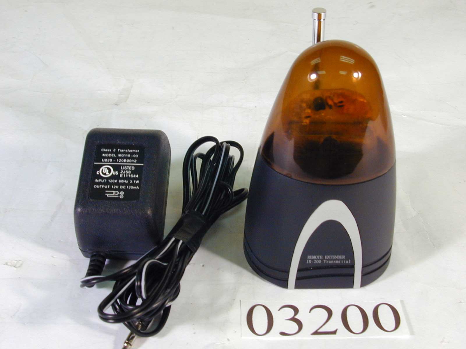
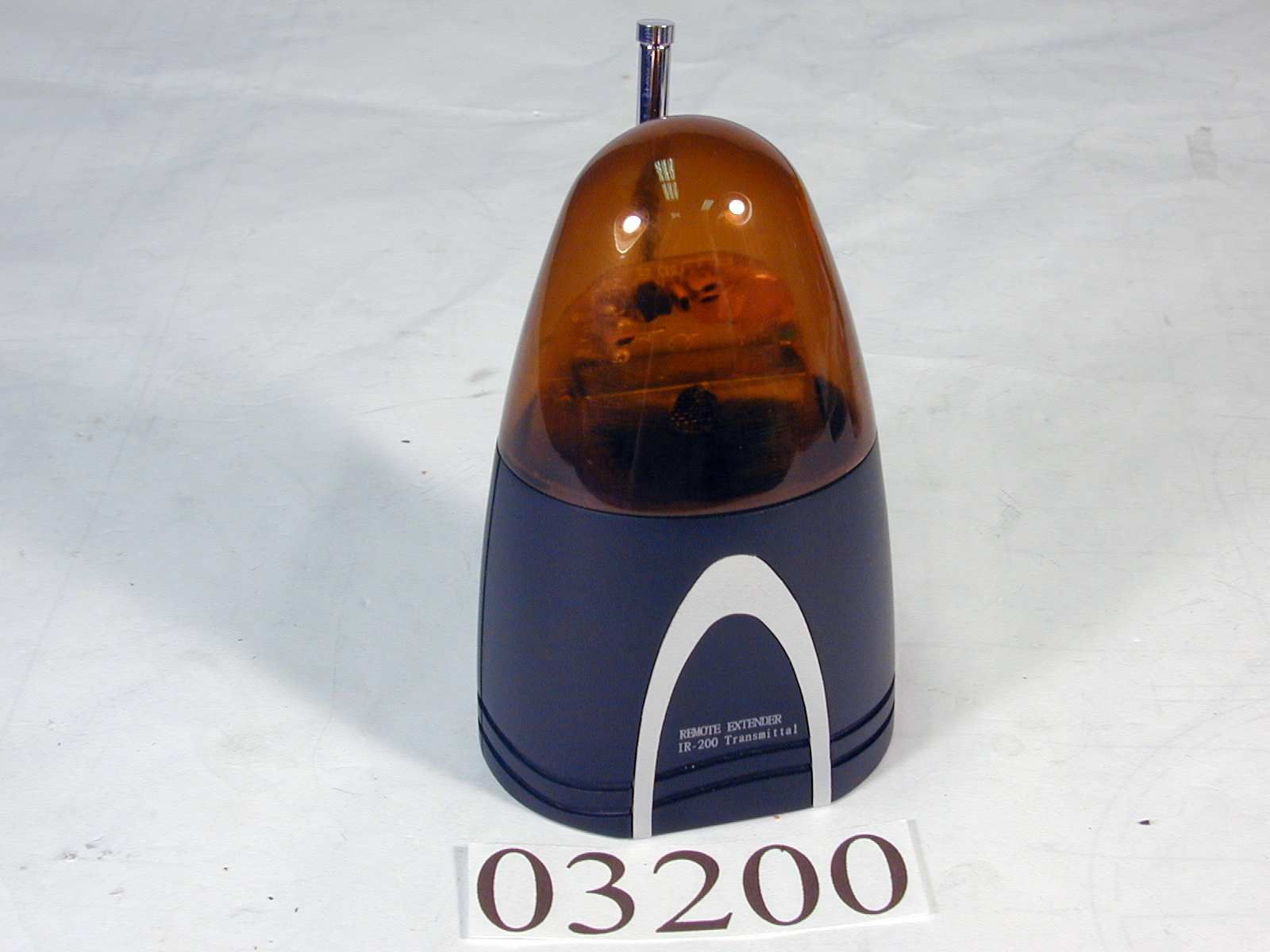
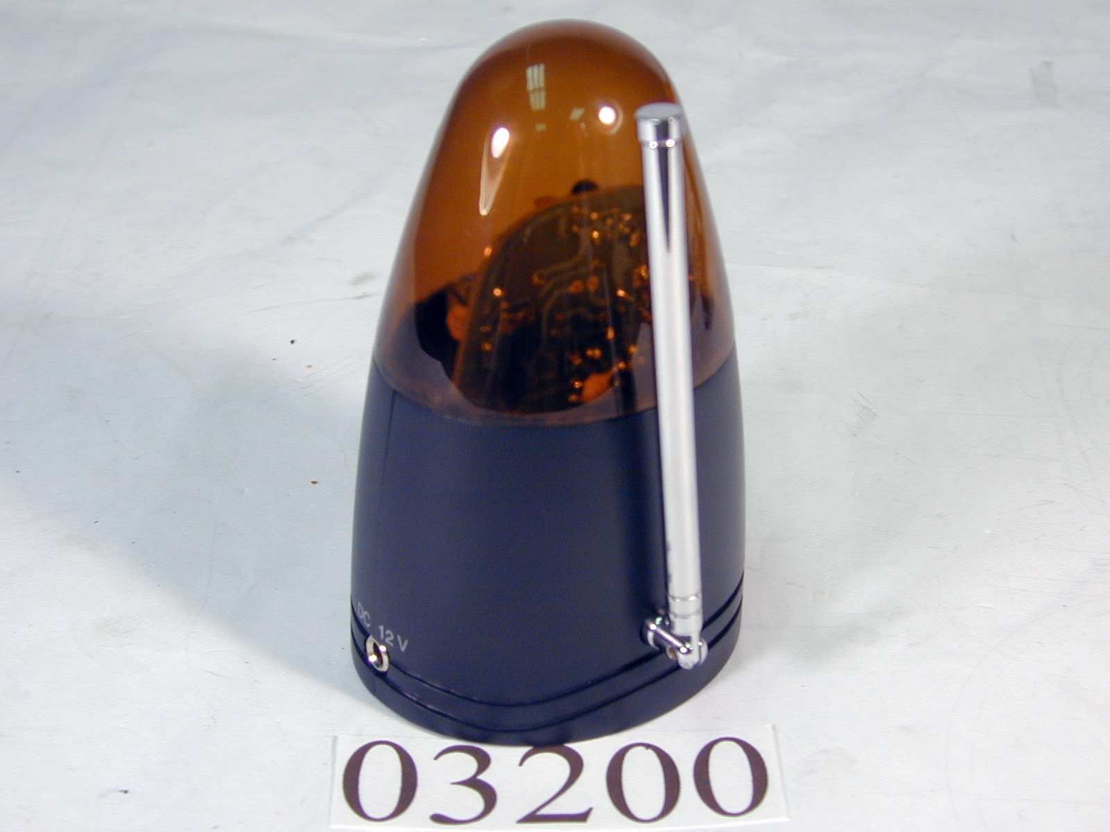
BY4IR100TRemote Control Extender
Trans Electric Co., Ltd.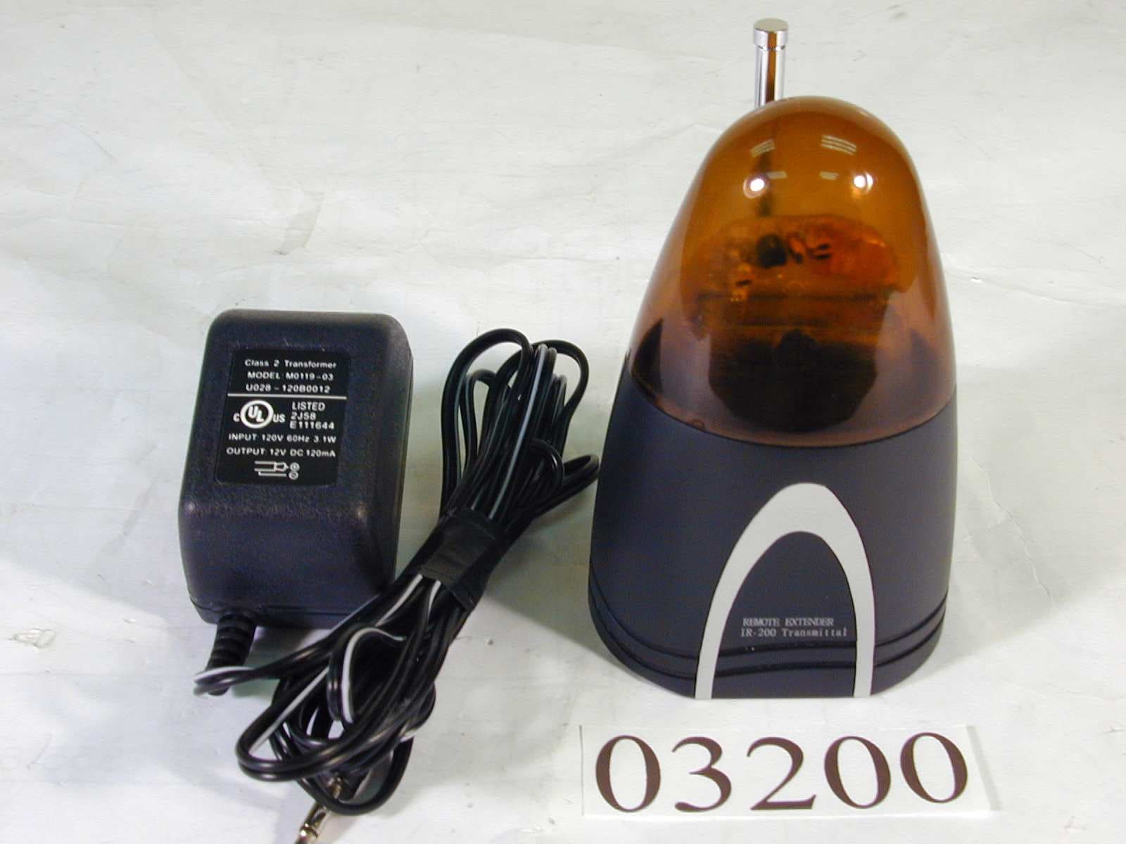
Click to zoom
Application Details
- Equipment Class
- DSC - Part 15 Security/Remote Control Transmitter
- Date of Grant
- Jul 11, 2000
- Application Purpose
- Original Equipment
- Date of Application
- Jul 02, 2000
- Equipment Note
- Remote Control Extender
- Frequency Range
- 418.00000000 - 418.00000000
- Company
- Trans Electric Co., Ltd.
- Country
- Taiwan
Documents & Files
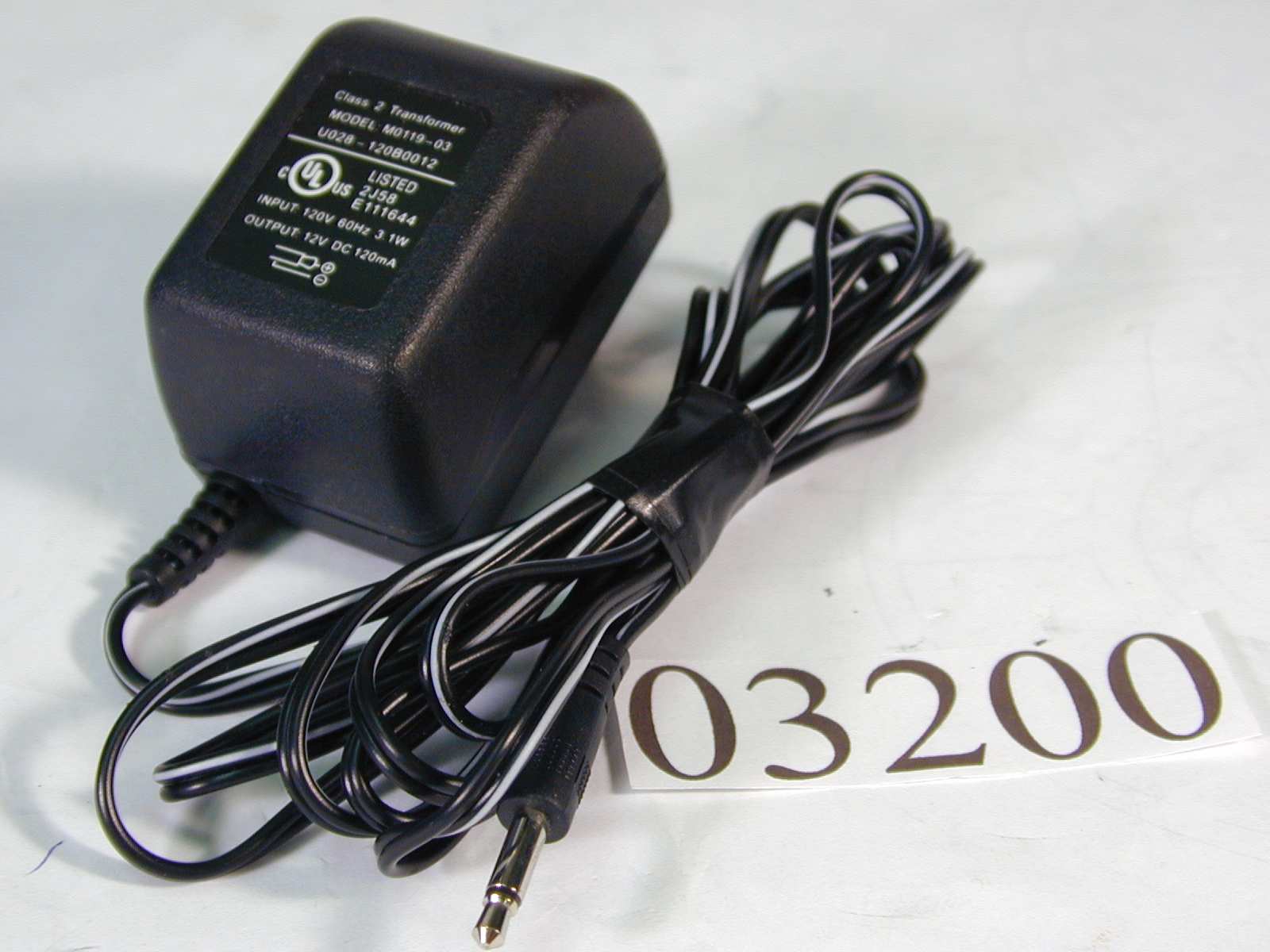
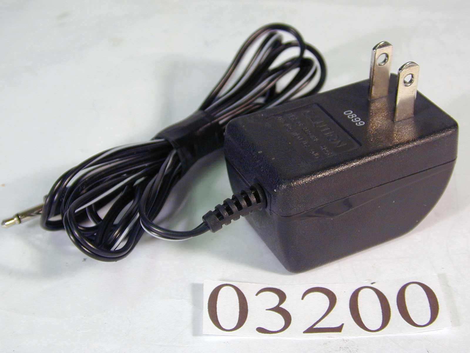
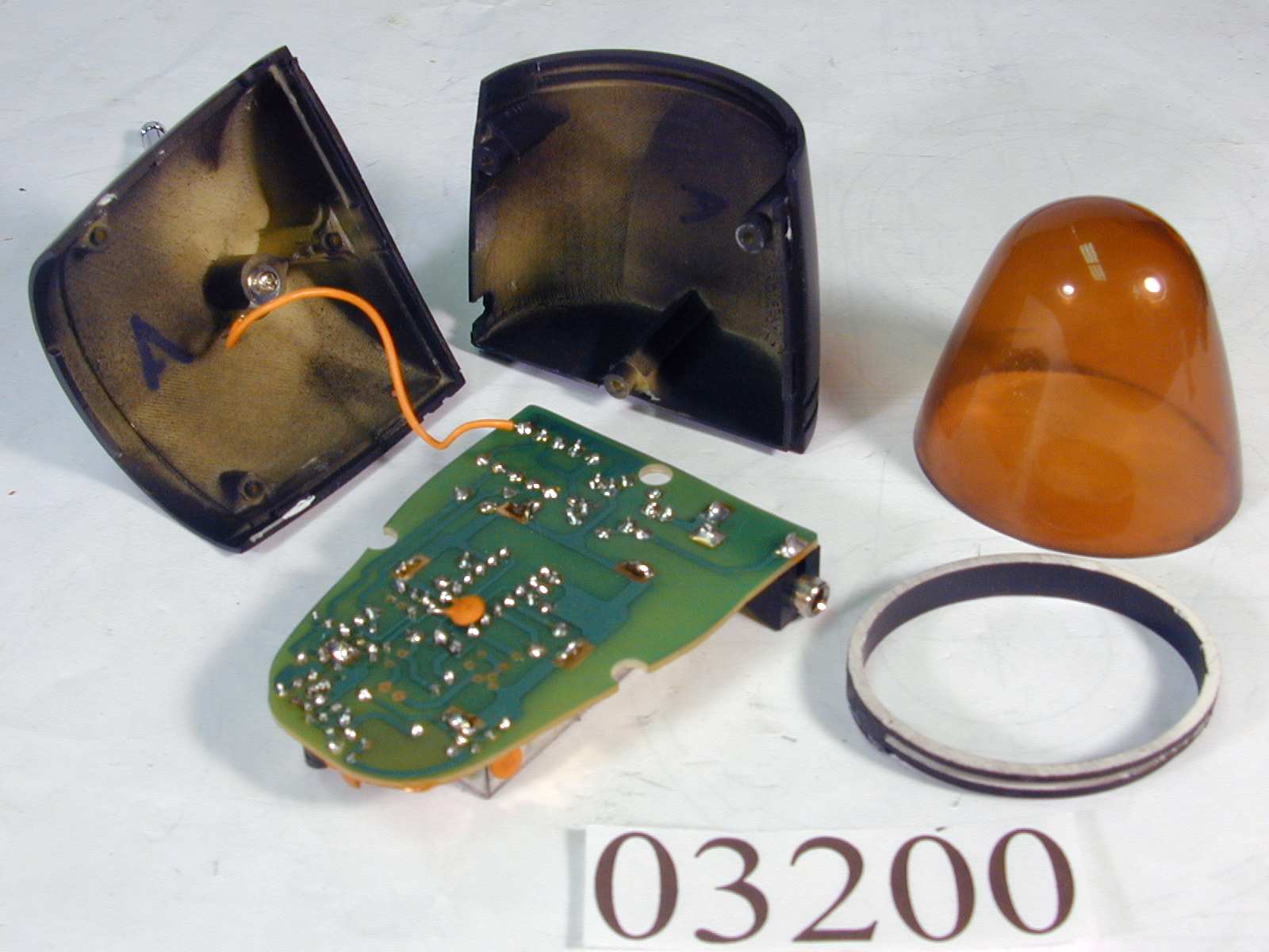
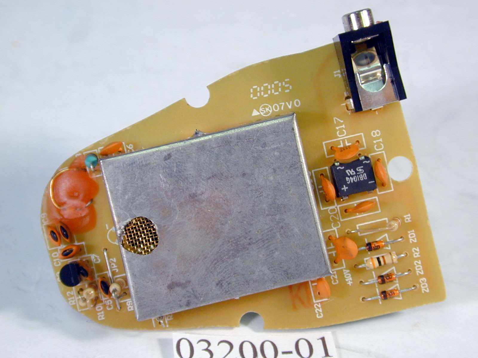
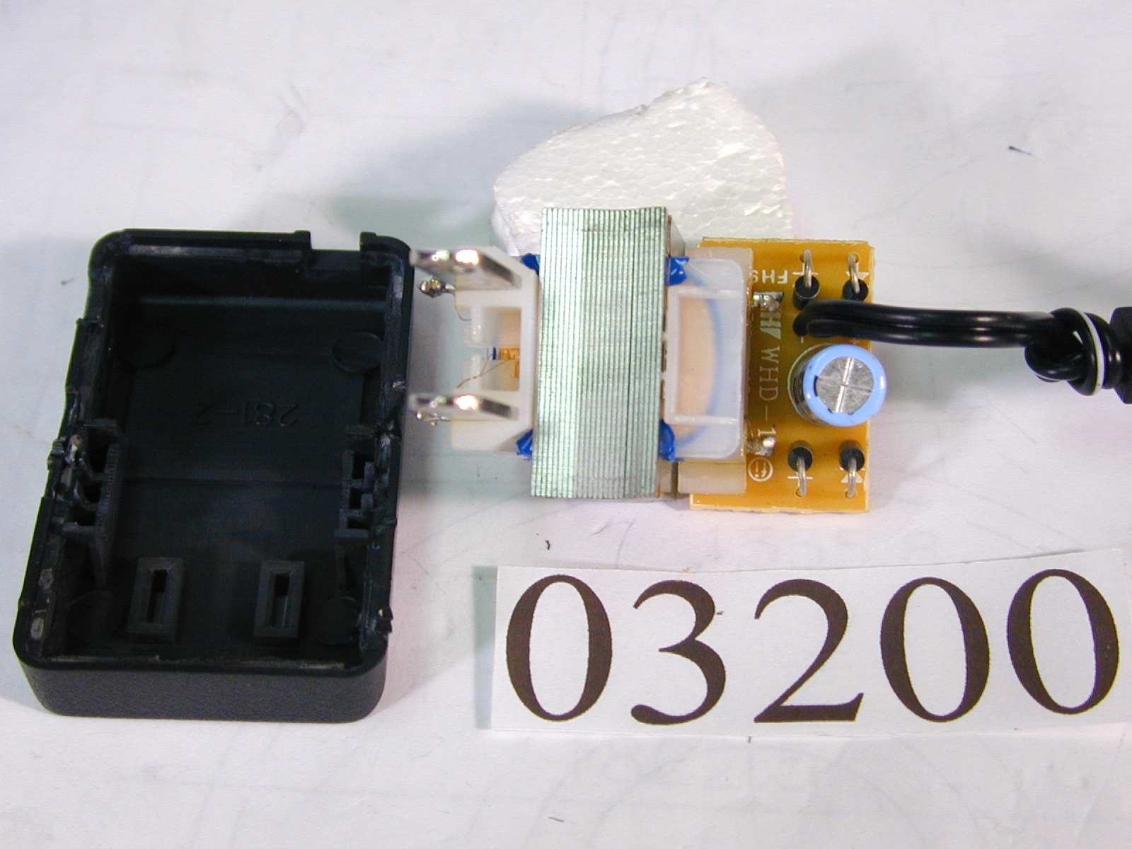
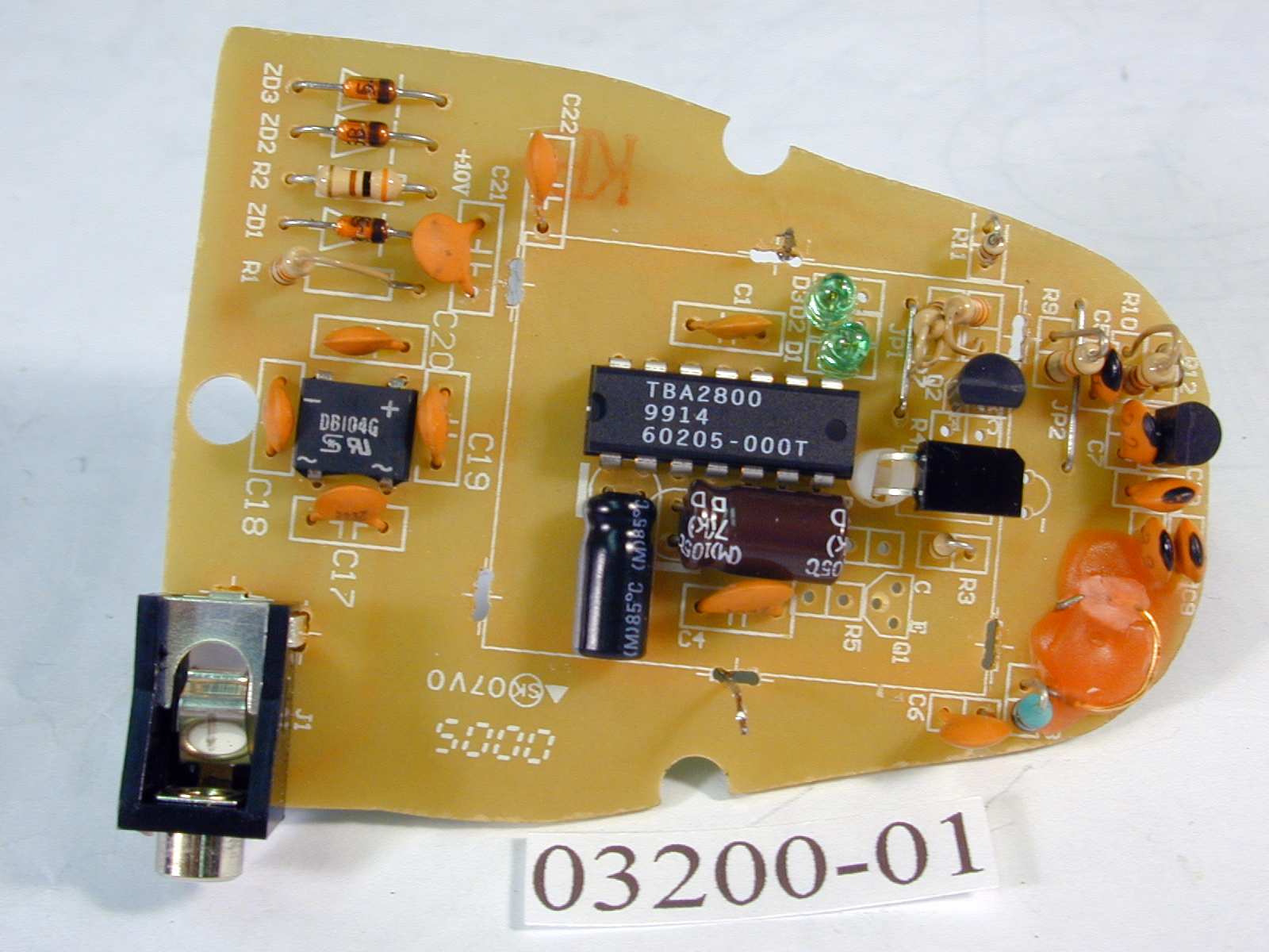
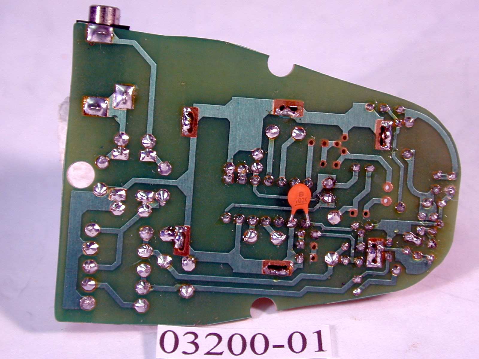
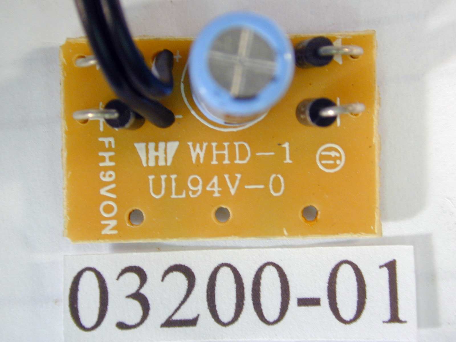
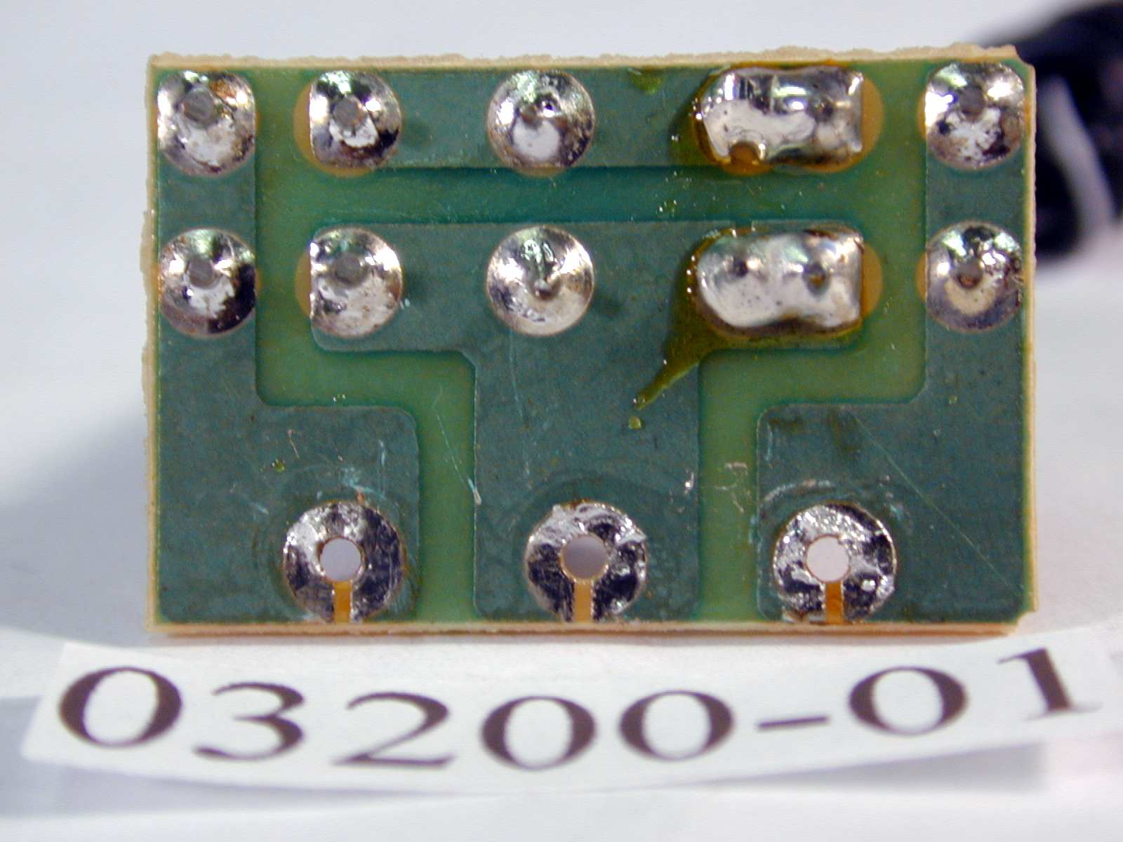
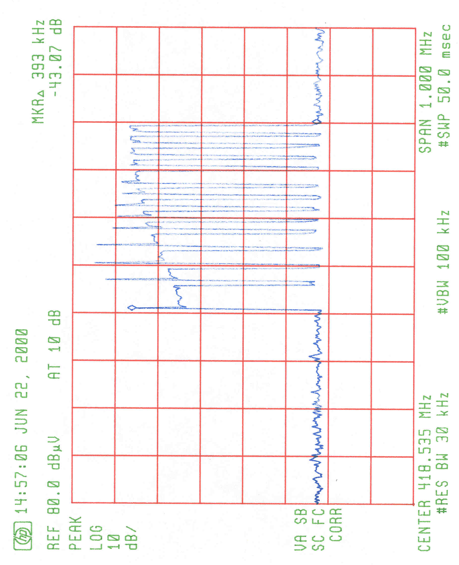
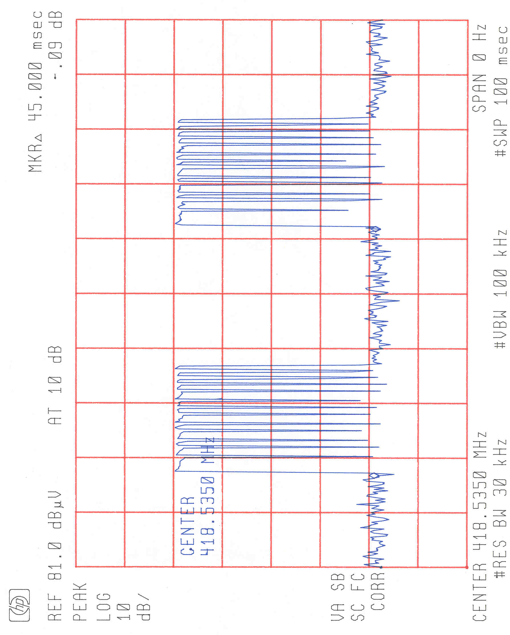
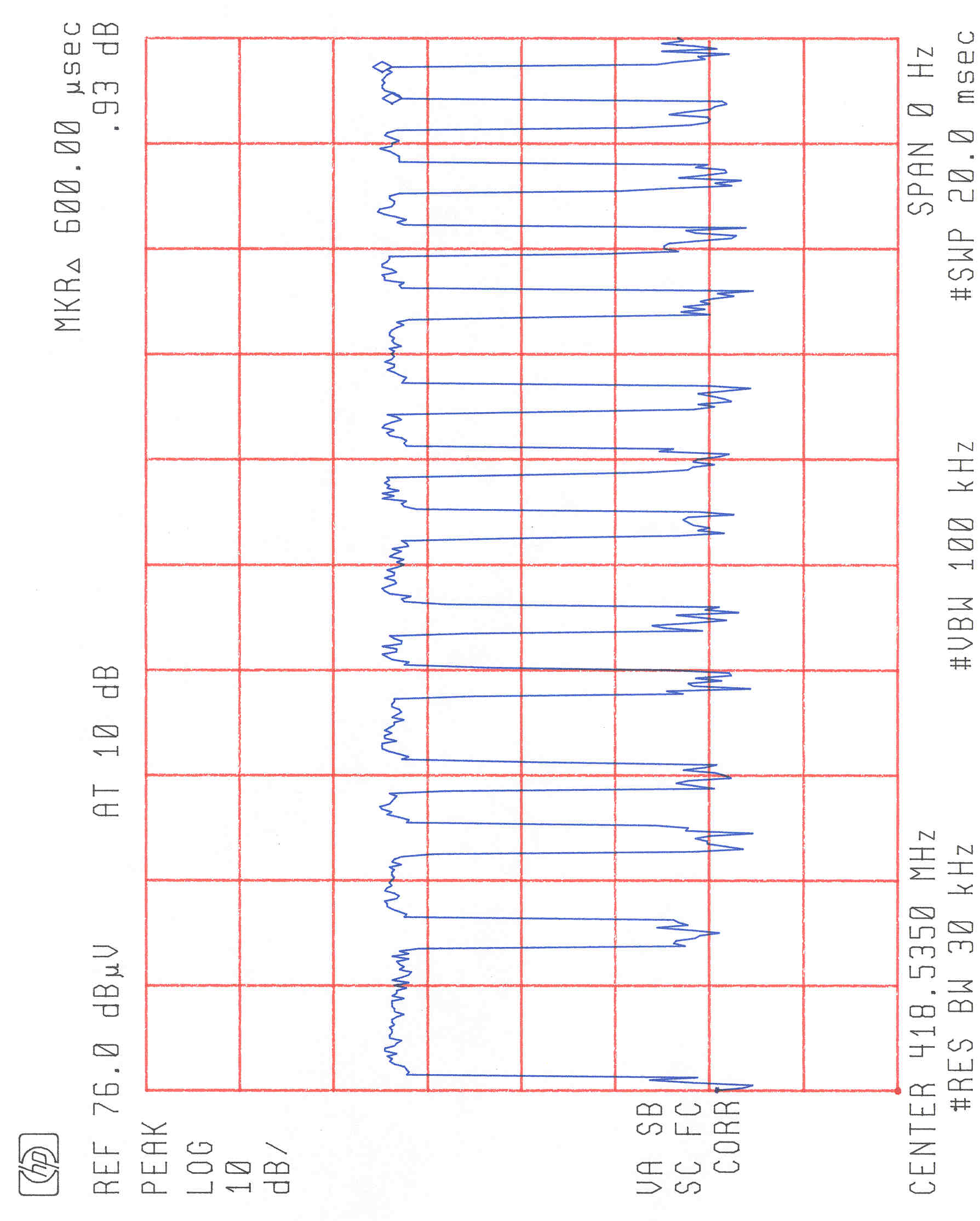
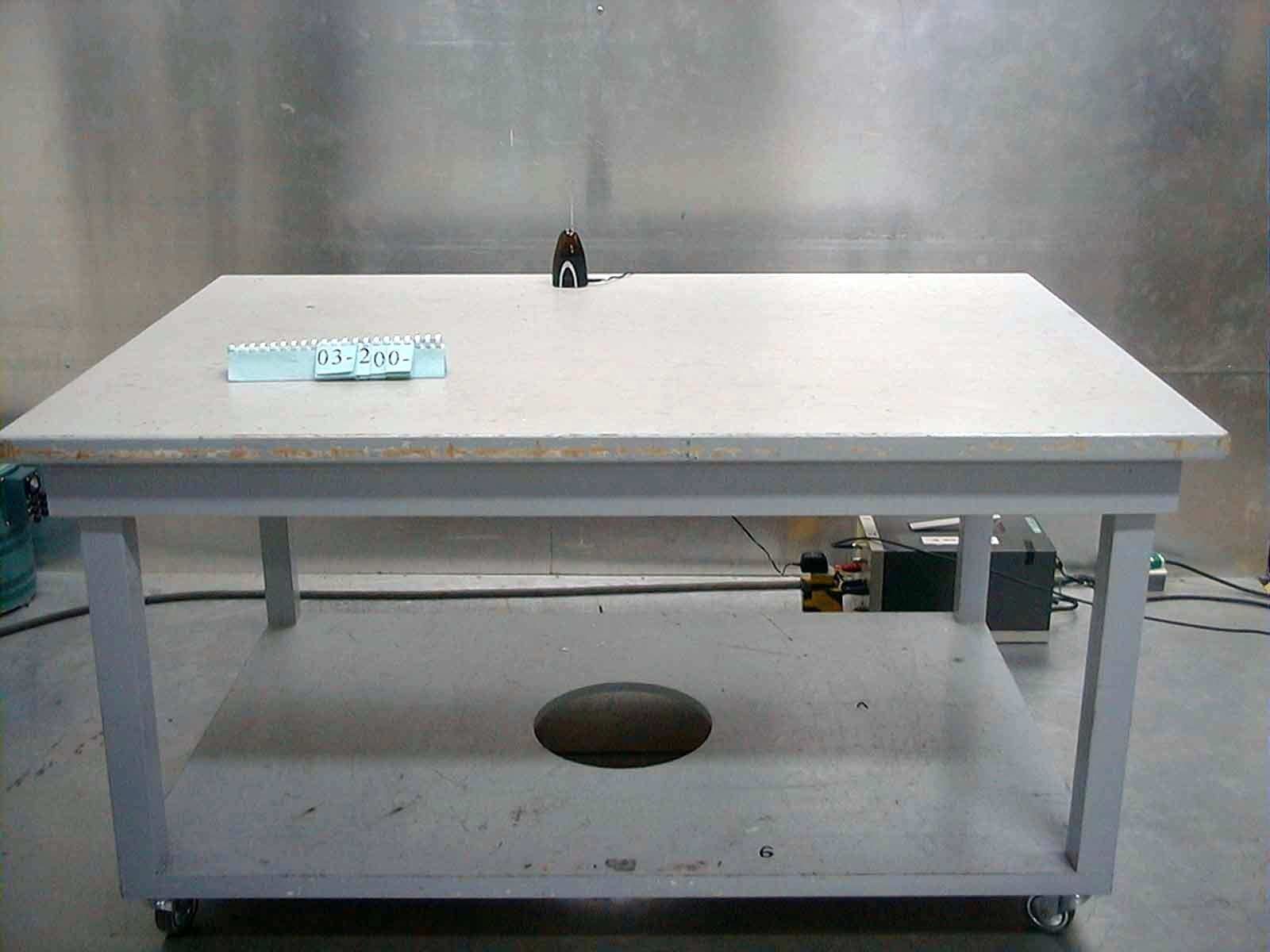
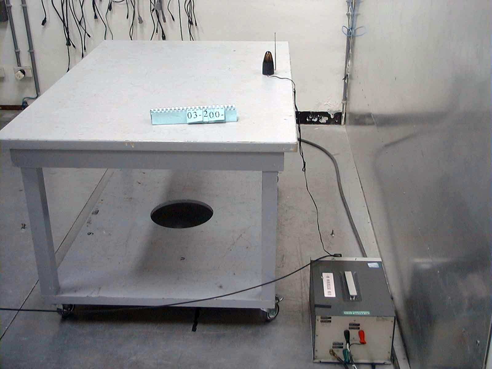
Document Text
Text extracted from the exhibit documents filed with the FCC. Open a document above to read the original.
Users Manual
REMOTE CONTROL EXTENDER DSC-IR100A USER MANUAL Product Description Applications The Remote operation of electronics products that utilize IR (Infrared) remote control technology such as: The DSC-IR100A Wireless Infrared Remote Control Extender enables you to extend their range of your present Infrared IR Remote Control so that you can operate VCRs, stereos, Cable Converter, Satellite receivers, etc. Virtually any where within your home. Unlike ordinary remote controls which are only effective in close range. " line of sight" use, The DSC-IR100A uses radio frequencies and can operate through walls, doors, around corners, etc. Television VCR's (Video Cassette Recorders) CDs (Compact Disc) DVD's (Digital Video Disc) LDP's (Laser Disc Players) C a b l e C o n v e r t e r B o x es Satellite Receivers A udio / H i-Fi Stereo Sys tems Wireless Video Sender Systems Any (IR) Remote Controlled Devices Installation Transmitter: Receiver / Probe: You will be using your normal IR remote control and "aiming" it at DSC- IR100A IR extender transmitter. 1. Plu g the suppli ed AC adapter into any standard electrical wall outlet. 2. Connect the other end of the AC ada pter cable in the"power in" socket located on the side of your transmitter unit. 3. Place the transmitter in the remote location so that it is in the line of si ght of the position where you are located (couch, chair, bed, etc.) so that you can "aim" your remote control at the transmitter. 1. Plug the supplied AC adapter into any standard electrical wall outlet. 2. Connect the other end of the AC adapter cable into the "power in" socket located on the side of the receiver unit. 3. Place the DSC-IR100A receiver in a high, line-of-sight position facing in front of the electronic device you are going to control. Be certain that there are no obstructions between the DSC-IR100A receiver and the infrared 4. In situation where it is not possible or convenient to place the DSC-IR 100A a high location, or near the equipment being controlled, and have the receiving window of the Plug one end of the probe cable into the jack located on the side of the DSC-IR100A receiver. Attach the other end of the probe to the IR receiving attached to the probe. receiving window of the equipment. receiver in line-of-sight of the controlled equipment, a remote probe is supplied. The remote pr obe enables you to place the DSC-IR100A receiver in probe transmit the IR data directly to the IR equipment. window of the equipment being controlled using to double stick tape INSTALLATION DIAGRAM B. Stereo System with remote Probe: A. Stereo System: D. VCR / TV /Wireless Video System with remote Probe: C. VCR / TV /Wireless Video System: Care and Maintenance Keep the DSC-IR100A Remote Extender dry. If it gets wet, wipe it dry immedi ately. Use and store the DSC-IR100A onl y in normal temperature environm ents. Extreme temperature can shorten the life of electronic devices Handle the DSC-IR100A gently and carefully. Dropping it can damage the circuit board anc can cause it to work improperly. Keep the DSC-IR100A away from dust and dirt, which can cause wear of parts. Wipe the DSC-IR100A with a damp cloth occasionally to keep it Do not use harsh chemicals, cleaning solvents, or strong detergents. premature looking new. Specifications Operating Voltage .......................................105-130 VAC, 60Hz Power Consumption (pair)............................4 Watts Max Transmission Frequency...............................418 MHz + / - 1 MHz
Block Diagram
1 2 3 4 ABCD 4 3 2 1 DCBA IR DETECTOR LPF ANDDRIVER ASK MODULATOR RF OSCILLATOR ANTENNA IR SENSOR REGULATOR REGULATOR DC POWER +5V +10V +12V BLOCK DIAGRAM OF DSC IR100A
Cover Letter(s)
EDERAL COMMUNICATIONS COMMISSION Declaration of Conformity The following equipment: Product Name: Remote Control Extender Trade Name: RECOTON Model Number: DSC-IR100A FCC ID: BY4IR100T is herewith confirmed to comply with the requirements of FCC Part 15 Rules, The operation is subject to the following two conditions: (1) This device may not caused harmful interference, and (2) This device must accept interference received including interference that may cause undesired operation. The result of electromagnetic emission has been evaluated by ETC EMI Laboratory (NVLAP LAB CODE: 200133-0) and showed in the test report: ET89S-03-200 It is understood that each unit marketed is identical to the device as tested, and any changes to the device which could adversely affect the emission characteristics will require retest. The following importer / manufacturer is responsible for this declaration: Company Name: TRANS ELECTRIC CO., LTD Company Address: 765 CHUNGSAN ROAD, SEC. 2, HUATANG, CHANGHUA, TAIWAN Telephone: 886-4-7633361 Facsimile: 886-4-7627018 Person is responsible for making this declaration: Paul Lin Senior Project Engineer Name (Full name)Position / Title Legal SignatureDate : June 27, 2000
Operational Description
DSC-ID100A working principals ir; infrared ray; remote control is spread used at family house, unfortunately ir natural is working under line of sight , So ir remote control is no way to work properly room by room due to space shielding by wall . Including carrier and coding, ir remote control signal detected by ir sensor. Then the sensor transfer current to voltage and amplified by following booster circuit. The colpitts LC oscillator resonate at 418MHz, trigger to oscillate is controlled by boosted ir signal. In other words, via the ASK; Amplitude Shift Keying; modulation, ir signal was carried on the 418MHz radio. Using the basic regenerative receiver to recover the modulated IR signal, which drive ir-led to duplicate ir remote control signal.
Operational Description
SPECIFICATIONS ITEM NO DSC-IR100A Transmitter: Transmit Frequency418 MHz Modulation TypeASK Transmit Power (EIRP)1mW (FCC) Frequency Accuracy ± 1 MHz Harmonics output- 40dBc, MAX Operating Temperature6mA (Stand by), 35mA typ. (on) Power SupplyDC Power Adapter Input AC110V, 60Hz Output DC 12V, 100mA DC IN Jack3.5 mm Receiver: Operation Frequency418 MHz Input Sensitivity-85dBm, Min Receiving range from transmitter30meter, typical Operating temperature 0 ° ~ 40 ° C IR Emitter Half angle ± 60 ° Horizontal Operation Current35 mA (typical) Power SupplyDC Power Adapter Input AC110V, 60Hz Output DC 12V, 100mA DC IN jack3.5mm External IR LED Jack2.4mm mono phone Approved by • Test by •
Schematics
1 2 3 4 A BC D 4 3 2 1 D CB A C3/2u2C0165 12345678 91011121314 C4/103PC0216 C1/102PC0254 D1/IR DIODEB0658 R3/100A0633 OUT- OUT+ TBA2800 C2/100uC0189 R8/3K3A0249 R7/4K7A0202 R9/18KA0175 R12/100A0633 R11/100A0633 Q2/C9014B0059 Q3/9018 B0177 C7/2P2 C0141 L1/1tV0509 +10V C8/3P3C0266 ANTENNA/RODK0236+D0335 L3/3u3HV0376 C9/1P8C0321 C10/1P8C0321 C6/2200PC0054 C5/15PC0121 R10/2K2A0620 J1/DC JACKJ0556 AC 1 AC 2 + 3 - 4 U2/DB-4B0403 C17/104PC0062 C20/104PC0062 C19/104P C0062 C18/104PC0062 ZD1/5V1B0267 ZD2/5V1B0267 ZD3/5V1B0267 R1/1KA0146 R2/270A0148 C22/104PC0062 C21/104PC0062 +5V IC1 D1/4148B0005D4/4148B0005 1 TBA2800/IC1B0659 R1310K
Test Report
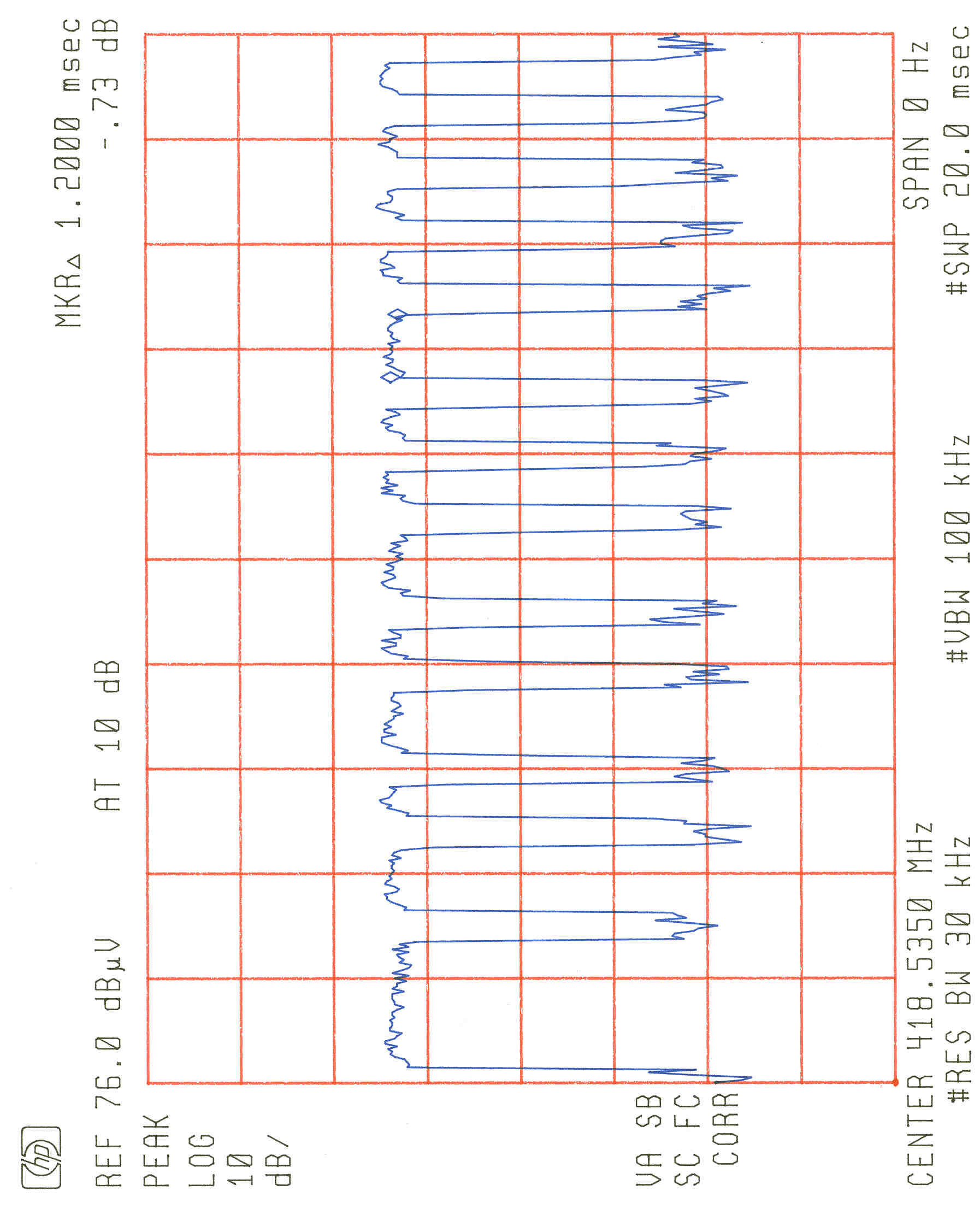
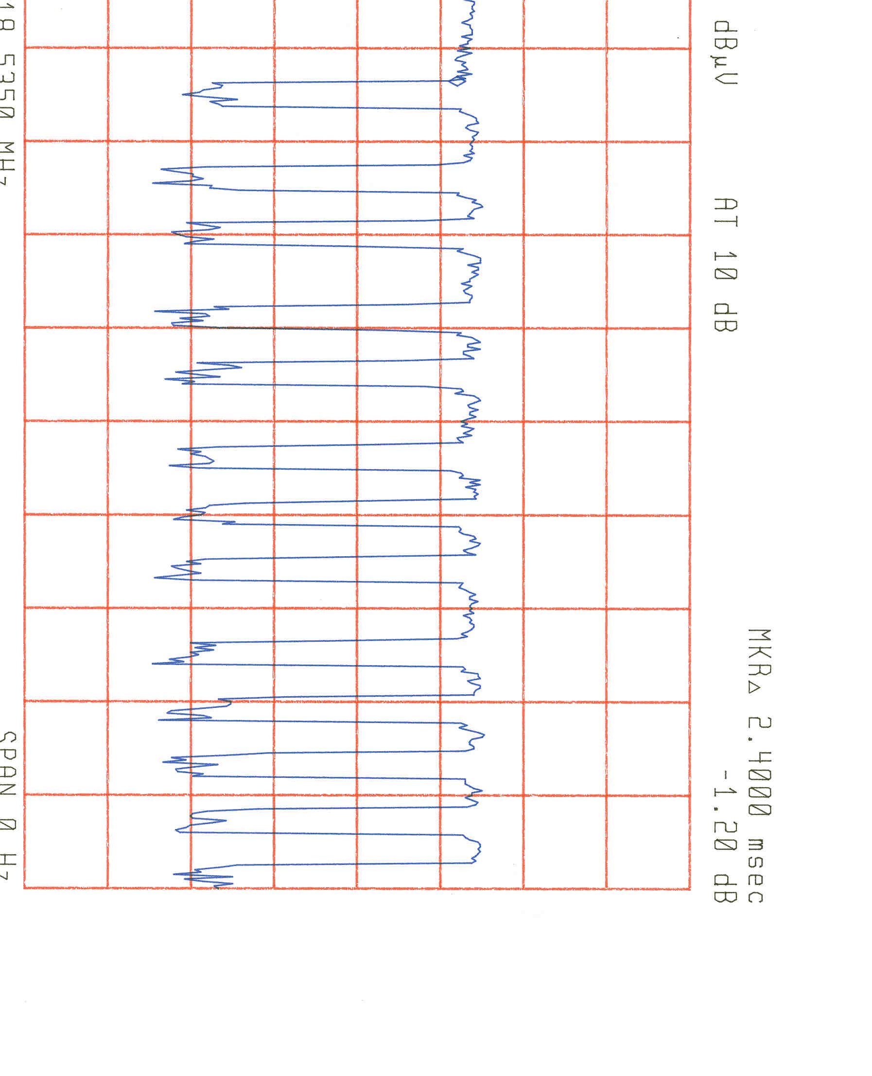
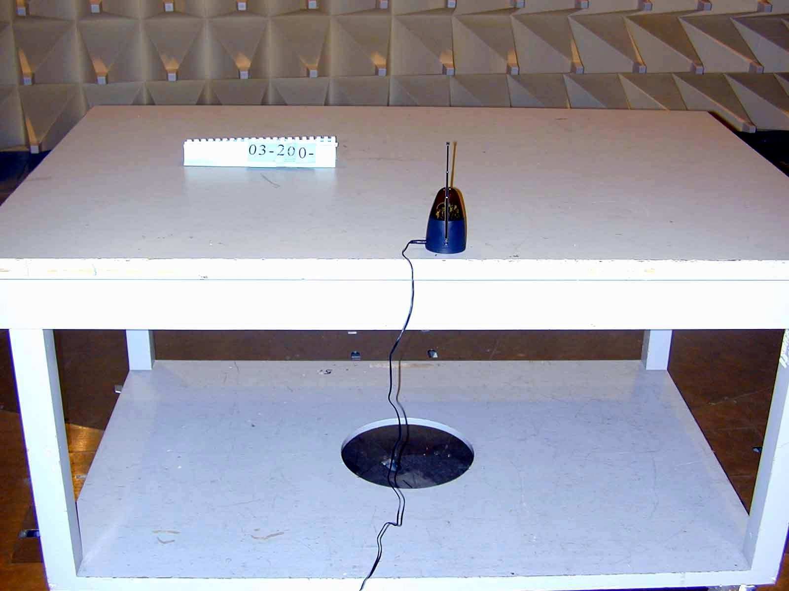
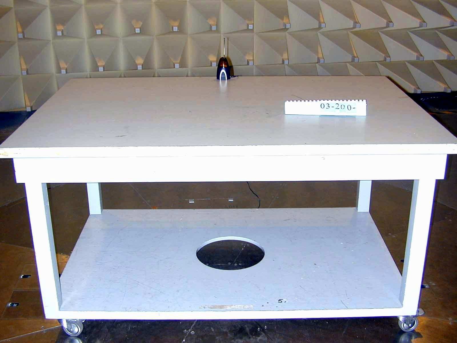
FCC ID.: BY4IR100T Rev. No 1.0 FCC Part 15 Subpart C EMI TEST REPORT of E.U.T. : Remote Control Extender FCC ID. : BY4IR100T MODEL : DSC-IR100A Working Frequency : 418MHz for APPLICANT : Trans Electric Co., Ltd. ADDRESS: 765 Chungsan Road, Section 2, Huatang, Changhua, TAIWAN Test Performed by ELECTRONICS TESTING CENTER, TAIWAN NO. 8 LANE 29, WENMIMG ROAD, LOSHAN TSUN, KWEISHAN HSIANG, TAOYUAN, TAIWAN, R.O.C. Tel:(03)3276170-3276174 Fax:(03)3276188 Report Number : ET88S-05-062 ETC Report No.:ET89S-03-200FCC ID.: BY4IR100T Rev. No 1.0 TEST REPORT CERTIFICATION Applicant: Trans Electric Co., Ltd. 765 Chungsan Road, Section 2, Huatang, Changhua, TAIWAN Manufacturer: Trans Electric Co., Ltd. 765 Chungsan Road, Section 2, Huatang, Changhua, TAIWAN Description of EUT: a) Type of EUT: Remote Control Extender b) Trade Name: RECOTON c) Model No.: DSC-IR100A d) FCC ID: BY4IR100T e) Working Frequency : 418MHz f) Power Supply: AC120V/60Hz g) Adapter: I/P AC 110V/60Hz O/P DC 12V, 100mA Regulation Applied: FCC Rules and Regulations Part 15 Subpart C (1996) I HEREBY CERTIFY THAT; The data shown in this report were made in accordance with the procedures given in ANSI C63.4 and the energy emitted by the device was founded to be within the limits applicable. I assume full responsibility for accuracy and completeness of these data. Note : 1. The results of the testing report relate only to the items tested. 2. The testing report shall not be reproduced except in full, without the written approval of ETC. Test Date : June 22, 2000 Test Engineer : Approve & Authorized Signer : Win-Po Tsai, Supervisor, NVLAP Signatory EMC Dept. of ELECTRONICS TESTING CENTER, TAIWAN ETC Report No.:ET89S-03-200FCC ID.: BY4IR100T Rev. No 1.0 Table of Contents Page 1. GENERAL INFORMATION ........................................................................................................................................ 1 1.1 P RODUCT D ESCRIPTIO N ................................................................................................................................................... 1 1.2 C HARACTERISTICS OF D EVICE : ........................................................................................................................................ 1 1.3 T EST M ETHODOLOGY ...................................................................................................................................................... 1 1.4 T EST F ACILITY ................................................................................................................................................................. 1 2. DEFINITION AND LIMITS.......................................................................................................................................... 2 2.1 D EFINITION ..................................................................................................................................................................... 2 2.2 R ESTRICTED B ANDS OF O PERATION ................................................................................................................................. 2 2.3 L IMITATION ..................................................................................................................................................................... 2 2.4 L ABELIN G R EQ UIREMEN T ................................................................................................................................................. 4 2.5 U SER I NFORMATION ........................................................................................................................................................ 4 3. RADIATED EMISSION MEASUREMENT................................................................................................................. 5 3.1 A PPLICABLE S TANDARD .................................................................................................................................................. 5 3.2 M EASUREMEN T P ROCEDURE ............................................................................................................................................ 5 3.3 T EST D ATA ...................................................................................................................................................................... 7 3.4 F IELD S TREN GTH C ALCULATIO N ...................................................................................................................................... 8 3.5 R ADIATED T EST E QUIPMENT ............................................................................................................................................ 8 3.6 M EASURIN G I N STRUMEN T S ETUP ..................................................................................................................................... 9 3.7 R ADIATED M EASUREMEN T P HOTOS ................................................................................................................................. 9 4. BANDWIDTH OF EMISSION.................................................................................................................................... 10 4.1 A PPLICABLE S TANDARD P LO T G RAPHIC OF B ANDWIDTH ............................................................................................... 10 4.2 B ANDWIDTH T EST E QUIPMENT ...................................................................................................................................... 10 4.3 T EST R ESULT ................................................................................................................................................................. 10 5. CONDUCTED EMISSION MEASUREMENT........................................................................................................... 11 5.1 A PPLICABLE S TANDARD ...............................................................................................................…
Text truncated - open the document above for the full version.
Contact Information
Applicant
Grace Wang(Vice-General Manager, Intel' sales Dept.)
Technical Contact
Electronics Testing Center, TaiwanJoseph Lu
[email protected]886-3-328 0026
No. 8, Lane 29, Wen-Ming RD., Lo-Shan Tsun, · Taoyuan Hsien · Taiwan
Non-Technical Contact
Electronics Testing Center, TaiwanMina Lin
Test Firm
Electronics Testing Center, TaiwanWinpo Tsai
Technical Specifications
| # | Rule Parts | Frequency Range | Power Output | Tolerance |
|---|---|---|---|---|
| 1 | 15C | 418 MHz - 418 MHz | - | ppm |
Other Applications from Trans Electric Co., Ltd.
BY4WTR1500C
Sep 18, 2024Wireless HD Transmitter & Receiver Kit
Equipment Class
NII - Unlicensed National Information Infrastructure TX
BY4BRX5200A
Sep 25, 2022Portable Bluetooth Wireless Transmitter & Receiver
Equipment Class
DSS - Part 15 Spread Spectrum Transmitter
BY4WFD5000PRO
Jan 17, 20224K UHD Wireless Presentation Receiver
Equipment Class
DTS - Digital Transmission System
BY4WFD1500PRO
Jan 17, 2022Full-HD Wireless Presentation Receiver
Equipment Class
DTS - Digital Transmission System
BY4WTR6000TX
Jul 28, 2021HD Wireless Conference System
Equipment Class
NII - Unlicensed National Information Infrastructure TX