BY4IR520Wireless Remote Extender
Trans Electric Co., Ltd.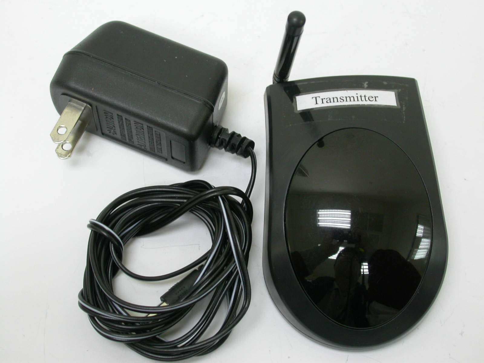
Click to zoom
Application Details
- Equipment Class
- DSC - Part 15 Security/Remote Control Transmitter
- Date of Grant
- Mar 31, 2005
- Application Purpose
- Original Equipment
- Date of Application
- Mar 31, 2005
- Equipment Note
- Wireless Remote Extender
- Frequency Range
- 418.25000000 - 418.25000000
- Company
- Trans Electric Co., Ltd.
- Country
- Taiwan
Documents & Files
Document Text
Text extracted from the exhibit documents filed with the FCC. Open a document above to read the original.
Users Manual
WIRELESS REMOTE EXTENDER USER MANUAL 1511951 Product Description Applications The Remote operation of electronic products that utilize IR (Infrared) remote control technology are: The Wireless Remote Extender enables you to extend the range of your present Infrared IR Remote Control up to 100 feet, so that you can operate VCRs, stereos, Cable Converter, Satellite receivers, etc, virtually anywhere within your home. Unlike ordinary remote controls which are only effective in close range, “line of sight” use. The Wireless Remote Extender uses radio frequencies and can operate through walls, doors, around corners, etc. Televisions VCR's (Video Cassette Recorders) CD Players DVD Players LDP's (Laser Disc Players) Cable Converter Boxes Satellite Receivers Audio / Hi-Fi Stereo Systems Wireless Video Sender Systems Any (IR) Remote Controlled Devices 1 Installation Transmitter: Receiver / Probe: You will be using your normal IR remote control and “aiming” it at the extender transmitter. 1. Plug the supplied AC adapter into any standard electrical wall outlet. 2. Connect the other end of the AC adapter cable in the “power in” socket located on the side of your transmitter unit. 3. Place the transmitter in the remote location so that it is in the line of sight of the position where you are located (couch, chair, bed, etc.) so that you can “aim” your remote control at the transmitter. 1. Plug the supplied AC adapter into any standard electrical wall outlet. 2. Connect the other end of the AC adapter cable into the “power in” socket located on the side of the receiver unit. 3. Place the receiver in a high, line-of-sight position facing the front of the electronic device you are going to control. Be certain that there are no obstructions between the receiver and the infrared receiving window of the equipment. line-of-sight of the controlled equipment, a remote probe is supplied. Plug one end of the probe cable into the jack located on the side of the receiver. Attach the other end of the probe to the IR receiving window of the equipment being controlled using double stick tape attached to the probe. The remote probe enables you to place the receiver in a high location, or near the equipment being controlled, and have the probe transmit the IR data directly to the IR receiving window of the equipment. 4. In situations where it is not possible or convenient to place the receiver in 2 INSTALLATION DIAGRAM B. Stereo System with remote Probe: A. Stereo System: Stereo Speaker Wire Receiver Wall Transmitter IR Remote Control IR Remote Control Wall Transmitter Receiver Probe IR Signal RF Signal 3 Stereo Speaker Wire D. VCR / TV /Wireless Video System with remote Probe: C. VCR / TV /Wireless Video System: VCR TV Receiver Wall Transmitter 2.4GHz Wireless Video Sender 2nd TV VCR TV Receiver Wall Transmitter 2nd TV 2.4GHz Wireless Video Sender Probe 4 Care and Maintenance Keep the IR Remote Extender dry. If it gets wet, wipe it dry immediately. Use and store the IR Remote Extender only in normal temperature environments. Extreme temperature can shorten the life of electronic devices. Handle the IR Remote Extender gently and carefully. Dropping it can damage the circuit board and can cause it to work improperly. Keep the IR Remote Extender away from dust and dirt, which can cause Wipe the IR Remote Extender with a damp cloth occasionally to keep it looking new. Do not use harsh chemicals, cleaning solvents, or strong detergents. premature wear of parts. Specifications Operating Voltage .......................................105-130 VAC, 60Hz Power Consumption (pair)............................4 Watts Max Transmission Frequency...............................418 MHz + / - 1 MHz Interference Your extender might cause TV or radio interference even when it is operating properly. To determine whether your extender is causing the interference, turn off your extender. If the interference goes away, your extender is causing it. Try to eliminate the interference by: • moving your extender away from the receiver • connecting your extender to an outlet that is on a different electrical circuit from the receiver • contacting your local electronic store for help If you cannot eliminate the interference, you may be required to stop using your extender. This device complies with PART 15 of the FCC rules and with RSS-210 of Industry Canada. Operation is subject to the following two conditions: (1) this device may not cause harmful interference, and (2) this device must accept any interference received, including interference that may cause undesired operation. NOTE: The changes or modifications not expressly approved by the party responsible for compliance could void the user’s authority to operate the equipment. To comply with the FCC RF exposure compliance requirements, this device and its antenna must not be co-located or operated in conjunction with any other antenna or transmitter. 5 6 LIMITED WARRANTY Who is Providing This Warranty? • Orbyx Electronics, LLC (“Orbyx”), as the distributor of this Nexxtech™ product (your “Product”). What Does This Warranty Cover? • This warranty covers defects in materials or workmanship in your Product under normal use and conditions. What is the Period of Coverage? • This warranty covers your Product for 90 days from the original purchase date. Who Is Covered? • This warranty covers the original consumer purchaser. Coverage terminates if you sell or otherwise transfer your Product. What Will We Do To Correct Problems? • We will repair your Product or replace your Product with a new or reconditioned equivalent product, at our option. How Do You Get Service? • Call Orbyx TOLL FREE at 1-866-363-3059 for instructions for obtaining warranty service from Orbyx’s authorized service providers. • Or, return your Product directly to the retail store from which you purchased the Product. • When you obtain service for your Product, you must provide a purchase receipt (or other proof of the original purc…
Text truncated - open the document above for the full version.
Cover Letter(s)
1 Subject:FW: Trans Electric Co Ltd, FCC ID: BY4IR520, Assessment NO.: AN05T4677, Notice#1 From: hsieh Sent: Thursday, March 31, 2005 6:20 PM Subject: Re: Trans Electric Co Ltd, FCC ID: BY4IR520, Assessment NO.: AN05T4677, Notice#1 Question #1: The device is not manually operated. Instead it is automatically activated by IR signal from an IR remote control. Section 6 of the test report indicated that "The transmitter is operated manually and active time is 0.04 seconds after being released". Please explain how you make the measurement, is there any button that can be released? The EUT is an IR remote extender. It will not auto transmit any signal if there is no IR signal received from any IR remote control. So, the IR receiver module is the switch. If the botton on IR remote control is released, IR remote contrl stops transmitting IR signal to EUT, then EUT will stop transmitting the RF signal, too. In section 6 of the test report, we released the switch. That means we need to use a remote control to "release" the IR receiver switch. About the question #2: The size of EUT is "L x W x H = 9.3cm x 6.3cm x 3.1cm" . It's smaller than the palm size. So we can bear the statement (FCC15.19) in the user manual. It you have any questions please feel free to discuss with me. Best regards, Joe The items indicated above must be submitted before processing can continue on the above referenced application. Failure to provide the requested information within 30 days of the original e-mail date may result in application dismissal and forfeiture of the filing fee. Also, please note that partial responses increase processing time and should not be submitted. Any questions about the content of this correspondence should be directed to the e-mail address listed below the name of the sender.
External Photos
ETC Report No.: ET94S-03-028-01 Page A1 of A1 FCC ID: BY4IR520 ANNEX A: EXTERNAL CONSTRUCTION PHOTOS OF EUT 1. Outside view 1 of EUT 2. Outside view 2 of EUT
Internal Photos
ETC Report No.: ET94S-03-028-01 Page B1 of B3 FCC ID: BY4IR520 ANNEX B: INTERNAL CONSTRUCTION PHOTOS OF EUT 1. Inside View 1 of EUT 2. Inside View 2 of EUT ETC Report No.: ET94S-03-028-01 Page B2 of B3 FCC ID: BY4IR520 3. Inside View 3 of EUT 4. Adapter ETC Report No.: ET94S-03-028-01 Page B3 of B3 FCC ID: BY4IR520 5. Front view of PCB 6. Rear view of PCB
Test Report
ETC Report No. : ET94S-03-028-01 Sheet 1 of 29 Sheets FCC ID.: BY4IR520 Rev. No 1.0 CONFORMANCE TEST REPORT FOR FCC 47 CFR, Part 15 Subpart C Report No.: ET94S-03-028-01 Client: TRANS ELECTRIC CO., LTD. Product: Wireless Remote Extender Model: IR520(NTSC) , IR500(PAL) , 1511951(NTSC) FCC ID: BY4IR520 Manufacturer/supplier: TRANS ELECTRIC CO., LTD. Date test item received: 2005/03/02 Date test campaign completed: 2005/03/02 Date of issue: 2005/03/07 The test result only corresponds to the tested sample. It is not permitted to copy this report, in part or in full, without the permission of the test laboratory. Total number of pages of this test report: 29 pages Total number of pages of photos: External photos 1 pages Internal photos 3 pages Setup photos 3 pages Test Engineer Checked By Approved By Mark Joe Hsieh Tsung-Ching Lin ELECTRONICS TESTING CENTER, TAIWAN NO.8, LANE 29, WEN-MING RD., LO-SHAN TSUN, KUI-SHAN HSIANG, TAOYUAN HSIEN 333 TAIWAN, R.O.C. TEL: (03) 3276170~4 INT: +886-3-3276170~4 FAX: (03) 3276188 INT: +886-3-3276188 ETC Report No. : ET94S-03-028-01 Sheet 2 of 29 Sheets FCC ID.: BY4IR520 Rev. No 1.0 TEST REPORT CERTIFICATION Client : TRANS ELECTRIC CO., LTD. Address : 765, Sec.2, Chungsan Rd., Huatang, Changhua, Taiwan, R.O.C. Manufacturer : TRANS ELECTRIC CO., LTD. Address : 765, Sec.2, Chungsan Rd., Huatang, Changhua, Taiwan, R.O.C. EUT : Wireless Remote Extender Trade name : PX (IR520(NTSC)) , PX(IR500(PAL)) , NEXXTECH(1511951(NTSC)) Model No. : IR520(NTSC),IR500(PAL),1511951(NTSC) Power Source : Adapter Model No.: NEXXTECH / JOD-28U-40 Input: 120Vac, 60Hz, 4W Output: DC 12Vdc, 120mA Regulations applied : FCC 47 CFR, Part 15 Subpart C (2004) The testing described in this report has been carried out to the best of our knowledge and ability, and our responsibility is limited to the exercise of reasonable care. This certification is not intended to believe the sellers from their legal and/or contractual obligations. The compliance test is only certified for the test equipment and the results of the testing report relate only to the item tested. The compliance test of this report was conducted in accordance with the appropriate standards. It’s not intention to assure the quality and performance of the product. This report shall not be reproduced except in full, without the approval of ETC. This report must not be used by the client to claim product endorsement by NVLAP or any agency of the U.S. Government. Laboratory Introduction: Electronics Testing Center, Taiwan is recognized, filed and mutual recognition arrangement as following: 1 ISO9001: TüV Product Service 2 ISO/IEC 17025: BSMI, CNLA, DGT, NVLAP, CCIBLAC, UL, Compliance 3 Filing: FCC, Industry Canada, VCCI 4 MRA: Australia, Hong Kong, New Zealand, Singapore, USA, Japan, Korea, China, APLAC through CNLA 5 FCC Registration Number: 90588, 91094, 91095 NVLAP Lab Code 200133-0 ETC Report No. : ET94S-03-028-01 Sheet 3 of 29 Sheets FCC ID.: BY4IR520 Rev. No 1.0 Table of Contents Page 1. GENERAL INFORMATION ......................................................................................................................................4 1.1 P RODUCT D ESCRIPTION .................................................................................................................................................4 1.2 C HARACTERISTICS OF D EVICE :......................................................................................................................................4 1.3 T EST M ETHODOLOGY ....................................................................................................................................................4 1.4 T EST F ACILITY ...............................................................................................................................................................4 2. DEFINITION AND LIMITS........................................................................................................................................5 2.1 D EFINITION ....................................................................................................................................................................5 2.2 RESTRICTED BANDS OF OPERATION...............................................................................................................................5 2.3 LIMITATION....................................................................................................................................................................6 2.4 L ABELING R EQUIREMENT ..............................................................................................................................................7 2.5 U SER I NFORMATION .......................................................................................................................................................7 3. RADIATED EMISSION MEASUREMENT..............................................................................................................8 3.1 A PPLICABLE S TANDARD .................................................................................................................................................8 3.2 M EASUREMENT P ROCEDURE .........................................................................................................................................8 3.3 T EST D ATA ..................................................................................................................................................................10 3.4 FIELD STRENGTH CALCULATION..................................................................................................................................14 3.5 RADIATED TEST EQUIPMENT.......................................................................................................................................14 3.6 M EASURING I NSTRUMENT S ETUP ....................................................................................…
Text truncated - open the document above for the full version.
Test Setup Photos
ETC Report No. : ET94S-03-028-01 Sheet 1 of 3 Sheets FCC ID. : BY4IR520 Photos of Radiation Measuring Setup ETC Report No. : ET94S-03-028-01 Sheet 2 of 3 Sheets FCC ID. : BY4IR520 ETC Report No. : ET94S-03-028-01 Sheet 3 of 3 Sheets FCC ID. : BY4IR520 Photos of Conduction Measuring Setup
Contact Information
Applicant
Grace Wang(Vice-General Manager, Intel' sales Dept.)
Test Firm
Electronics Testing Center, TaiwanWin-Po Tsai
Technical Specifications
| # | Rule Parts | Frequency Range | Power Output |
|---|---|---|---|
| 1 | 15.231 | 418.25 MHz - 418.25 MHz | - |
Other Applications from Trans Electric Co., Ltd.
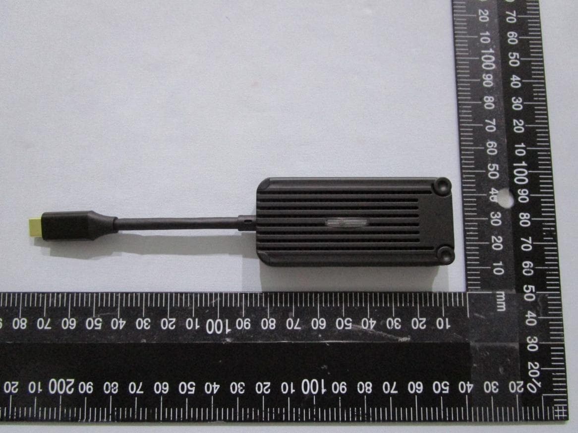
BY4WTR1500C
Sep 18, 2024Wireless HD Transmitter & Receiver Kit
Equipment Class
NII - Unlicensed National Information Infrastructure TX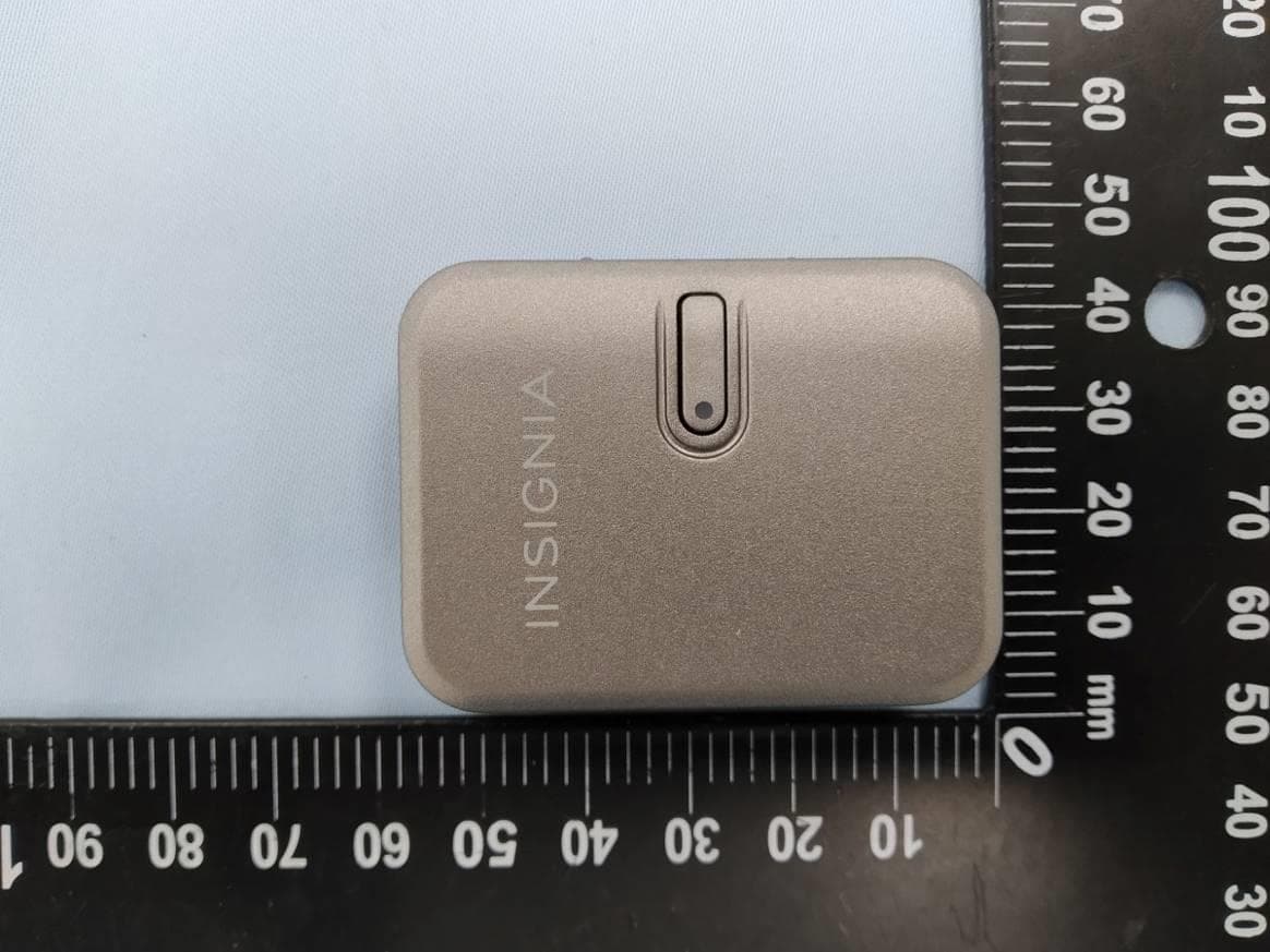
BY4BRX5200A
Sep 25, 2022Portable Bluetooth Wireless Transmitter & Receiver
Equipment Class
DSS - Part 15 Spread Spectrum Transmitter
BY4WFD5000PRO
Jan 17, 20224K UHD Wireless Presentation Receiver
Equipment Class
DTS - Digital Transmission System
BY4WFD1500PRO
Jan 17, 2022Full-HD Wireless Presentation Receiver
Equipment Class
DTS - Digital Transmission System
BY4WTR6000TX
Jul 28, 2021HD Wireless Conference System
Equipment Class
NII - Unlicensed National Information Infrastructure TX