BY4LFIRXWireless Remote Control Extender
Trans Electric Co., Ltd.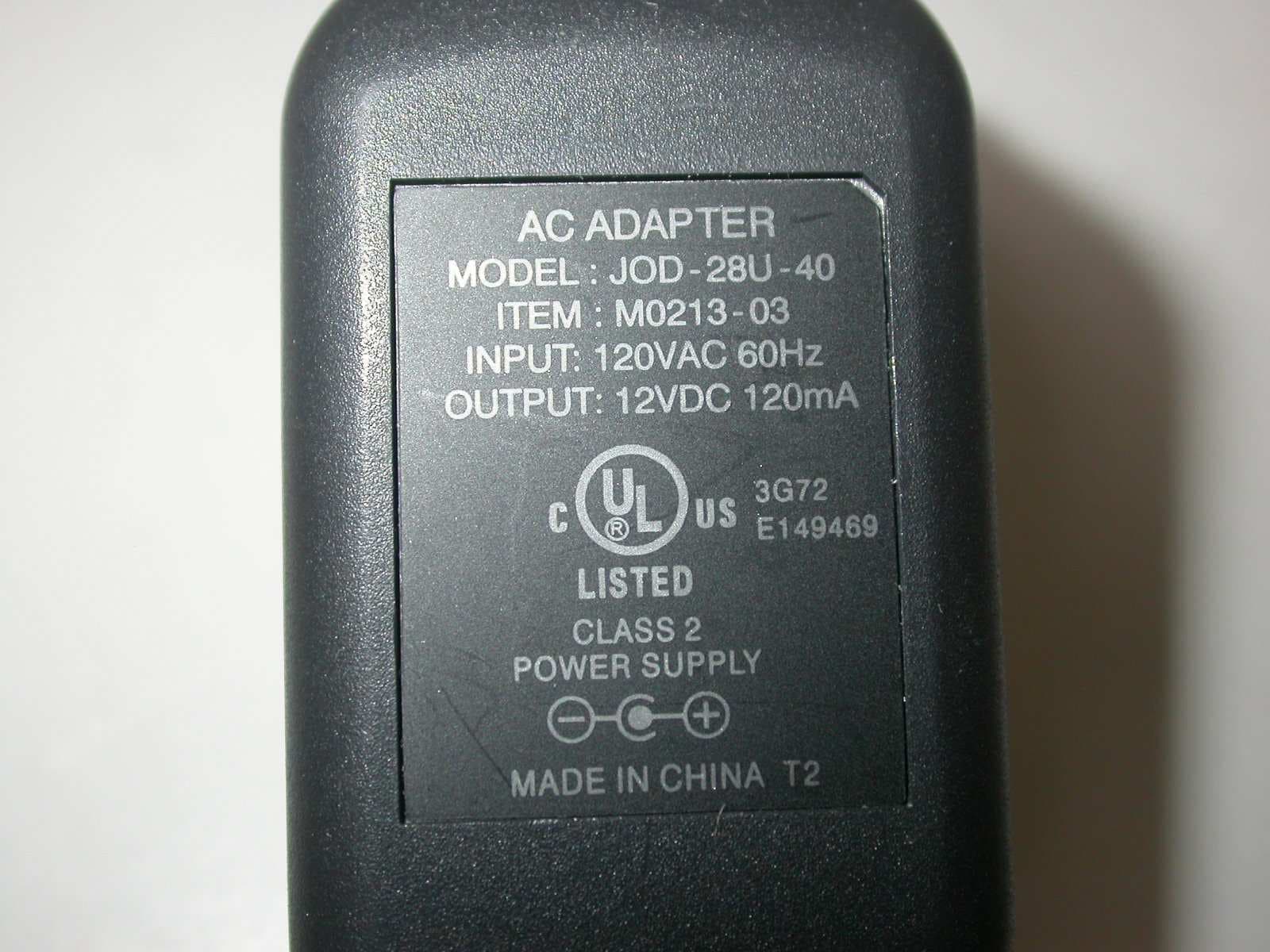
Click to zoom
Application Details
- Equipment Class
- DSC - Part 15 Security/Remote Control Transmitter
- Date of Grant
- Jan 16, 2007
- Application Purpose
- Original Equipment
- Date of Application
- Jan 16, 2007
- Equipment Note
- Wireless Remote Control Extender
- Frequency Range
- 418.34500000 - 418.34500000
- Company
- Trans Electric Co., Ltd.
- Country
- Taiwan
Documents & Files
Document Text
Text extracted from the exhibit documents filed with the FCC. Open a document above to read the original.
Users Manual
LF-IRX Remote Control Extender LF-IRX OWNER’S MANUAL Limited Warranty Audiovox Corporation (Audiovox) warrants this product against defects in materials or workmanship for one (1) year from the date of purchase. During this period, this product will be replaced without charge. This warranty does not cover any damage due to acts of nature, commercial use, accident, misuse, abuse or negligence. This warranty is only valid in the USA. Replacement as provided under this warranty is the exclusive remedy of the consumer. Audiovox shall not be liable for any incidental or consequential damages for breach of any express or implied warranty on this product, except to the extent that limitations of this sort are prohibited by applicable law. THERE ARE NO IMPLIED WARRANTIES OF MERCHANTABILITY OR FITNESS FOR A PARTICULAR PURCHASE EXCEPT TO THE EXTENT THAT IMPLIED WARRANTIES OR EITHER SORT ARE REQUIRED BY APPLICABLE LAW, AND IN SUCH CASE, EACH WARRANTY IS LIMITED IN DURATION TO THE ONE YEAR. TERK and the TERK logo are registered trademarks of AUDIOVOX Corp. For customer service and technical information:: 1.800.290.6650 For Customer Service Visit Our Website At www.terk.com Product Information,Photos, FAQ’s, Owner’s Manuals For customer serviceand technical information:: 8. To reduce the risk of electric shock, do not disassemble this product, but take it to a qualified serviceperson if service or repair work is required. Opening or removing covers may expose you to dangerous voltages or other risks and will void the warranty. Incorrect reassembly can cause electric shock when the product is subsequently used. 9. Unplug your LF-IRX from the wall outlet and contact a qualified electronic service technician if any of the following should occur: A. The plug is damaged or the cord has been broken or frayed. B. Liquid has been spilled into the product. C. The product has been exposed to rain or water. D. The product does not operate normally by following the operating instructions. E. The product has been dropped or otherwise damaged and will not work. F. The product exhibits a distinct change in performance. • No repairs to the unit(s) should be attempted by the customer. LF-IRX 2 0perating Precautions Precautions: To ensure safe and effective operation, please be sure to read and understand the following precautions before operating your TERK Remote Control Extender. The following basic safety precautions should always be followed to reduce the risk of fire, electric shock and personal injury: 1. Read and understand all of the instructions in this manual. 2. Follow all warnings and instructions indicated in the manual and on the product itself. 3. Do not use your LF-IRX in or near any body of water, such as a bath tub, washbowl, kitchen sink, or laundry tub, in a wet basement, or in or near a swimming pool. 4. Be sure to place your LF-IRX on a stable, level surface. Placing the product on any unstable surface may cause the product to fall. 5. Do not attempt to clean your LF-IRX while it is plugged in. Unplug the product from the wall outlet before cleaning. 6. Do not use liquid cleaners or aerosol cleaners to clean your LF-IRX. Clean only with a damp cloth. 7. This product should be operated only from the type of power source indicated on the marking label. LF-IRX 1 0perating Precautions (continued) • NOTE: This equipment has been tested and found to comply with the limits for remote control security devices in accordance with the specifications in sub parts C and E of part 15 of FCC rules. These limits are designed to provide reasonable protection against harmful interference in a residential installation. This equipment generates, uses and can radiate radio frequency energy and, if not installed and used in accordance with the instructions, may cause harmful interference to radio communications. However, there is no guarantee that Radio Frequency Energy does cause harmful interference to radio or television reception, which can be determined by turning the equipment off and on. We recommend the following steps to correct signal transmission problems: • Reorient or relocate the receiving antenna. • Increase the separation between the equipment and the Receiver. • If the Receiver and the component that is being operated are plugged into the same electrical outlet, plug the Receiver into a different outlet. Call Terk Tech Support 1- 800-942-TERK (8375) with any product or application questions. LF-IRX 3 System Contents Your TERK LF-IRX Remote Control Extender consists of two units (Transmitter(TX) Receiver (RX)), a triple infrared extension, and two AC adapters. Transmitter (TX): The Transmitter converts the infrared signals from your remote control into long-range RF signals that are sent to the Receiver. The LED lamp indicates that incoming signals are being detected. The unit contains an antenna and power cord. Receiver (RX): The Receiver converts the RF signals from the Transmitter back to the infrared signals used to control your components. The unit contains an antenna, power cord, and a jack for the Infrared Extension. The LED light indicates that a signal is being received. The Receiver Unit can be placed up to 100 feet away from the Transmitter Unit. Infrared Extension: The Infrared Extension can be used in situations where the Receiver can not be placed in front of the component(s) it is controlling. This device consists of 3 Infrared diodes connected to a 4 ft. extension wire and plug. It can be placed on up to 3 different components. 4 The LF-IRX can control virtually any household device that is operated via infrared remote control, including: • Satellite Receivers • Personal Video Recorders (TiVo, UltimateTV) • Cable Converter Boxes • VCRs • CD Players • Stereo Receivers • Tape Decks • DVD Players • TV Sets Compatible Components STEP 2: Setting Up the Receiver Where to Use: Use in the room where the AUDIO/VIDEO equipment’s infrared sensor is located. How to Install: 1. Plug the Receiver pow…
Text truncated - open the document above for the full version.
Cover Letter(s)
TRANS ELECTRIC CO., LTD. 765, Sec.2, Chungsan Rd, Huatang, Changhua, Taiwan. FCC ID: BY4LFIRX Device Name: Wireless Remote Control Extender Model No.: LF-IRX Date: 17/1/2007 Federal Communications Commission Dear Sir: Pursuant to Section 0.457 and 0.459 of the Commission’s Rules, the Applicant hereby requests confidential treatment of information accompanying this Application as outlined below: Schematics Block Diagram Operational Descriptions The above materials contain trade secrets and proprietary information not customarily released to the public. The public disclosure of these matters might be harmful to the Applicant and provide unjustified benefits to its competitors. The Applicant understands that pursuant to Rule 0.457, disclosure of this Application and all accompanying documentation will not be made before the date of the Grant for this application. Sincerely Yours, By: By: Philip Wang (Signature) (Printed) Title: Sales Manager Applicant: TRANS ELECTRIC CO.LTD. Address: 765, Sec.2 ChungsanRd, Huatang, Changhua, Taiwan. Tel: 886-4-763 3361 Fax: 886-4-762 7018
External Photos
ETC Report No.: 06-12-MAS-093-01 Page A1 of A2 FCC ID. : BY4LFIRX ANNEX A: EXTERNAL CONSTRUCTION PHOTOS OF EUT 1. Outside view 1 of EUT 2. Outside view 2 of EUT ETC Report No.: 06-12-MAS-093-01 Page A2 of A2 FCC ID. : BY4LFIRX 3. Adaptor
Internal Photos
ETC Report No.: 06-12-MAS-093-01 Page B1 of B3 FCC ID. : BY4LFIRX ANNEX B: INTERNAL CONSTRUCTION PHOTOS OF EUT 1. Inside View of EUT 2. antenna ETC Report No.: 06-12-MAS-093-01 Page B2 of B3 FCC ID. : BY4LFIRX 3. Front view of PCB 4. Front view of PCB ETC Report No.: 06-12-MAS-093-01 Page B3 of B3 FCC ID. : BY4LFIRX 5. Rear view of PCB 6. Rear view of PCB
Test Report
ETC Report No. : 06-12-MAS-093-01 Sheet 1 of 25 Sheets FCC ID.: BY4LFIRX Rev. No 1.0 CONFORMANCE TEST REPORT FOR FCC 47 CFR, Part 15 Subpart C Report No.: 06-12-MAS-093-01 Client: TRANS ELECTRIC CO., LTD. Product: Wireless Remote Control Extender Model: LF-IRX FCC ID: BY4LFIRX Manufacturer/supplier: TRANS ELECTRIC CO., LTD. Date test item received: 2006/12/08 Date test campaign completed: 2007/01/16 Date of issue: 2007/01/16 The test result only corresponds to the tested sample. It is not permitted to copy this report, in part or in full, without the permission of the test laboratory. Total number of pages of this test report: 25 pages Total number of pages of photos: External photos 2 pages Internal photos 3 pages Setup photos 2 pages Test Engineer Checked By Approved By Jeng De Hsu James Joe Hsieh ELECTRONICS TESTING CENTER, TAIWAN NO.8, LANE 29, WENMING RD., LESHAN TSUEN, GUISHAN SHIANG, TAOYUAN COUNTY, TAIWAN 33383, R.O.C. TEL: (03) 3276170~4 INT: +886-3-3276170~4 FAX: (03) 3276188 INT: +886-3-3276188 ETC Report No. : 06-12-MAS-093-01 Sheet 2 of 25 Sheets FCC ID.: BY4LFIRX Rev. No 1.0 Client : TRANS ELECTRIC CO., LTD. Address : 765, Sec.2, Chungsan Rd., Huatang, Changhua, Taiwan, R.O.C. Manufacturer : TRANS ELECTRIC CO., LTD. Address : 765, Sec.2, Chungsan Rd., Huatang, Changhua, Taiwan, R.O.C. EUT : Wireless Remote Control Extender Trade name : TERK Model No. : LF-IRX Power Source : Adapter : JOD-28BU-40 Input: 120Vac, 60Hz Output: DC 12VDC, 120mA Regulations applied : FCC 47 CFR, Part 15 Subpart C (2006) The testing described in this report has been carried out to the best of our knowledge and ability, and our responsibility is limited to the exercise of reasonable care. This certification is not intended to believe the sellers from their legal and/or contractual obligations. The compliance test is only certified for the test equipment and the results of the testing report relate only to the item tested. The compliance test of this report was conducted in accordance with the appropriate standards. It’s not intention to assure the quality and performance of the product. This report shall not be reproduced except in full, without the approval of ETC. This report must not be used by the client to claim product endorsement by NVLAP or any agency of the U.S. Government. Laboratory Introduction: Electronics Testing Center, Taiwan is recognized, filed and mutual recognition arrangement as following: 1 ISO9001: TüV Product Service 2 ISO/IEC 17025: BSMI, CNLA, DGT, NVLAP, CCIBLAC, UL, Compliance 3 Filing: FCC, Industry Canada, VCCI 4 MRA: Australia, Hong Kong, New Zealand, Singapore, USA, Japan, Korea, China, APLAC through CNLA 5 FCC Registration Number: 90588, 91094, 91095 NVLAP Lab Code 200133-0 ETC Report No. : 06-12-MAS-093-01 Sheet 3 of 25 Sheets FCC ID.: BY4LFIRX Rev. No 1.0 Table of Contents Page 1. GENERAL INFORMATION ......................................................................................................................................4 1.1 PRODUCT DESCRIPTION.................................................................................................................................................4 1.2 CHARACTERISTICS OF DEVICE:......................................................................................................................................4 1.3 TEST METHODOLOGY....................................................................................................................................................4 1.4 TEST FACILITY...............................................................................................................................................................4 1.5 MODIFICATION RECORD.................................................................................................................................................4 2. DEFINITION AND LIMITS........................................................................................................................................5 2.1 DEFINITION....................................................................................................................................................................5 2.2 RESTRICTED BANDS OF OPERATION...............................................................................................................................5 2.3 LIMITATION....................................................................................................................................................................6 2.4 LABELING REQUIREMENT..............................................................................................................................................7 2.5 USER INFORMATION.......................................................................................................................................................7 3. RADIATED EMISSION MEASUREMENT..............................................................................................................8 3.1 APPLICABLE STANDARD.................................................................................................................................................8 3.2 MEASUREMENT PROCEDURE.........................................................................................................................................8 3.3 TEST DATA..................................................................................................................................................................10 3.4 FIELD STRENGTH CALCULATION..................................................................................................................................12 3.5 RADIATED TEST EQUIPMENT.......................................................................................................................................12 3.6 MEASURING INSTRUMENT SETUP................................................................................................…
Text truncated - open the document above for the full version.
Test Setup Photos
ETC Report No. : 06-12-MAS-093-01 Sheet 1 of 2 Sheets FCC ID. : BY4LFIRX Photos of Radiation Measuring Setup ETC Report No. : 06-12-MAS-093-01 Sheet 2 of 2 Sheets FCC ID. : BY4LFIRX Photos of Conduction Measuring Setup
Contact Information
Applicant
Grace Wang(Vice-General Manager, Intel' sales Dept.)
Test Firm
Electronics Testing Center, TaiwanWin-Po Tsai
Technical Specifications
| # | Rule Parts | Frequency Range | Power Output |
|---|---|---|---|
| 1 | 15.231 | 418.345 MHz - 418.345 MHz | - |
Other Applications from Trans Electric Co., Ltd.
BY4WTR1500C
Sep 18, 2024Wireless HD Transmitter & Receiver Kit
Equipment Class
NII - Unlicensed National Information Infrastructure TX
BY4BRX5200A
Sep 25, 2022Portable Bluetooth Wireless Transmitter & Receiver
Equipment Class
DSS - Part 15 Spread Spectrum Transmitter
BY4WFD5000PRO
Jan 17, 20224K UHD Wireless Presentation Receiver
Equipment Class
DTS - Digital Transmission System
BY4WFD1500PRO
Jan 17, 2022Full-HD Wireless Presentation Receiver
Equipment Class
DTS - Digital Transmission System
BY4WTR6000TX
Jul 28, 2021HD Wireless Conference System
Equipment Class
NII - Unlicensed National Information Infrastructure TX