BY4SV1100Wireless Remote Control Extender
Trans Electric Co., Ltd.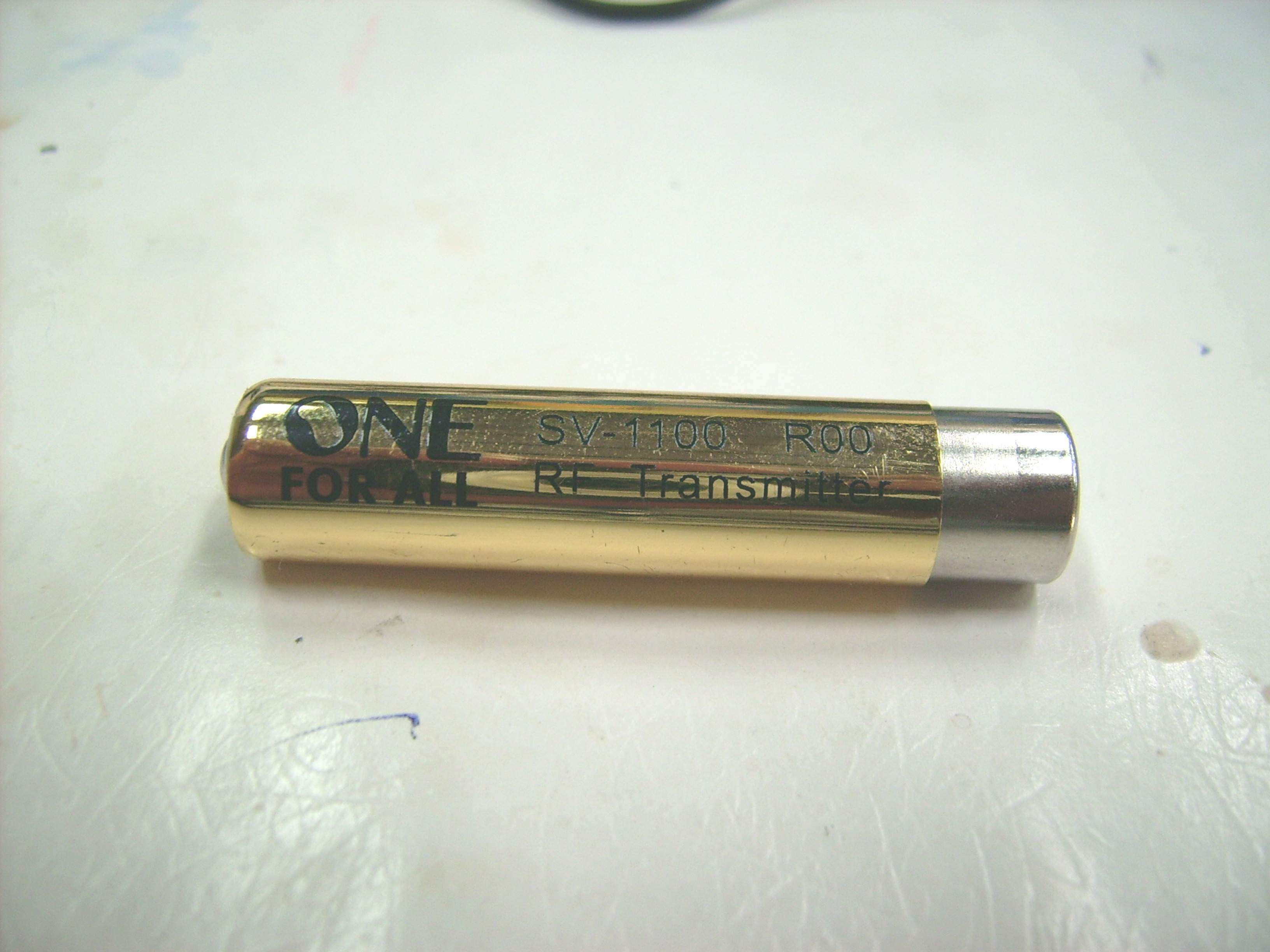
Click to zoom
Application Details
- Equipment Class
- DSC - Part 15 Security/Remote Control Transmitter
- Date of Grant
- Apr 24, 2007
- Application Purpose
- Original Equipment
- Date of Application
- Apr 24, 2007
- Equipment Note
- Wireless Remote Control Extender
- Frequency Range
- 417.97800000 - 417.97800000
- Company
- Trans Electric Co., Ltd.
- Country
- Taiwan
Documents & Files
Document Text
Text extracted from the exhibit documents filed with the FCC. Open a document above to read the original.
Users Manual
INTERFERENCE The RECEIVER can be interfered with an external RF signal. The LED (A/B) of the RECEIVER will blink even without pressing a key on the remote control. If this is the case, please try the below: 1. Try to move the RECEIVER (Reminder: The receiver also transmits IR signals, so try placing the receiver so that it also faces your devices.) 2. Reduce the antenna length. SAFETY PRECAUTIONS • This product should only be used with the CEC approved AC Power supply included in the packaging. • Inadequately protected or sensitive electronic equipment may be affected by the use of this product. • Before you start, please check whether or not this product can affect sur- rounding equipment. COMPLIANCE WITH FCC, IC RULES AND REGULATIONS This equipment has been tested and found to comply with the limits for a class B digital device, pursuant to part 15 of the FCC Rules. These limits are designed to provide reasonable protection against harmful interference in a residential installation. This equipment generates, uses and radi- ates radio frequency energy and if not installed and used in accordance with the instructions, may cause harmful interference to radio communications. However, there is no guarantee that interfer- ence will not occur in a particular installation. If this equipment does cause harmful interference to radio or television reception, which can be determined by turning the equipment off and on, the user is encouraged to try and correct the interference by one or more of the following measures: • RE-ORIENT OR RELOCATE THE RECEIVER ANTENNA. • INCREASE THE SEPARATION BETWEEN THE EQUIPMENT AND THE RECEIVER. • CONNECT THE EQUIPMENT INTO AN OUTLET THAT IS DIFFERENT FROM THAT TO WHICH THE RECEIVER IS CONNECTED • CONSULT THE DEALER OR AN EXPERIENCED RADIO/TELEVISION TECHNICIAN FOR HELP NOTE: Changes or modifications not expressly approved by the party responible for compliance could void the user’s authority to operate the equipment. In compliance with the FCC RF exposure requirements, this device and its antenna must not be co-located or operating in conjunction with any other antenna or transmitter. FCC Authorization Label This device complies with part 15 of the FCC Rules. Operation is subject to the following two con- ditions: 1. THIS DEVICE MAY NOT CAUSE HARMFUL INTERFERENCE AND 2. THIS DEVICE MUST ACCEPT ANY INTERFERENCE RECEIVED, INCLUDING INTERFERENCE THAT MAY CAUSE UNDESIRED OPERATION. FCC ID #: BY4SV1100 ADDITIONAL I NFORMATION This product does not have any user-serviceable parts. Opening the case, except for the battery cover on the base station, may cause permanent damage to your Remote Extender. Copyright 2007 by Universal Electronics Inc. No part of this publication may be reproduced, trans- mitted, transcribed, stored in any retrieval system, or transla ted to any language, in any form or by any means, electro nic, mechanical, magnetic, optical, manual, or otherwise, without prior written permission of Universal Electro nics Inc. For help via the Internet, visit us at: www.urcsupport.com/extender For help via e-mail, contact us at: [email protected] STEP 2: SELECTING THE FREqUENCY Set the Selection Switch (on the back of the RECEIVER) to... A : 58KHz (Try this setting if your Scientific Atlanta Explorer is not responding) B : 38KHz (Default setting and most common setting for IR controlled devices) C : Sensitivity lower e.g. other equipment using 418 MHz (external interference). See section: “Interference”. STEP 3: RECEIvER PLACEMENT Place the RECEIVER next to the corresponding device(s) you wish to control. STEP 4: CONNECTING THE IR b LASTER CAbLE Connect the IR Blaster Cable into the back of the RECEIVER and place the IR Eye(s) on the receiving window (IR sensor) of each hidden device you want to control. NOTE: There are 3 IR Eyes to control 3 separate devices. NOTE: Remove the adhesive tape on the bottom of the IR Eye to secure it on the front of the audio/video equipment IR sensor. STEP 5: APPLYING POWER TO THE RECEIvER Plug the power adaptor in the wall socket and connect the DC connector to the back of the RECEIVER. The POWER LED on the top of the RECEIVER will illuminate. YOUR REMOTE CONTROL EXTENDER IS NOW READY FOR USE RE-CHARGING THE 2/3 SI zE “AAA” bATTERY The Remote Control Extender’s receiver is also used to recharge the 2/3 size battery. The Remote Extender comes with 2 rechargeable batteries to ensure your RF remote is always ready for use. If your remote control is functioning at a shorter distance than normal (when the LED (A/B) of the RECEIVER does not blink when a key on the remote control is being pressed) then the battery needs to be recharged. 1. Remove the (2/3 “AAA” size) battery from your remote control. 2. Place the (2/3 “AAA” size) battery in the compartment located on the bottom of the RECEIVER. The LED (BAT) will light up. 3. The LED will switch off as soon as the (2/3 “AAA” size) battery is fully charged. NOTE: The RF operating range may vary depending on the overall battery charge (e.g. you may have to replace the “AA”/”AAA” alkaline batteries if the operating range decreases). Caution: Use only with supplied rechargeable battery. Risk of explosion if battery is installed by an incorrect type. INTRODUCTION The Remote Control Extender is a revolutionary device which will turn virtually any IR (Infra- red) remote control into an RF (Radio Frequency) remote control. No longer do your electronic devices need to be out in the open for you to control them. Additional benefits of the Remote Control Extender are: • Send signals through walls and ceilings. • Control Audio and Video devices which are placed out of sight. • RF Transmitter is available wherever the remote control is located. • Installation is as easy as changing a battery. Please ensure that all of the components below are included and follow the 5 Easy installa- tion steps below and start enjoying the power of RF control. THIS PACkAGE CONTAINS: 1. Remote Extender Receiver 2. IR…
Text truncated - open the document above for the full version.
External Photos
ETC Report No.: 07-03-MAS-084-01 Page A1 of A1 FCC ID.: BY4SV1100 ANNEX A: EXTERNAL CONSTRUCTION PHOTOS OF EUT 1. Outside view of EUT
ID Label/Location Info
16 mm FCC ID:BY4SV1100 FCC ID:BY4SV1100 字高:1.5mm
Internal Photos
ETC Report No.: 07-03--MAS-084-01 Page B1 of B3 FCC ID.: BY4SV1100 ANNEX B: INTERNAL CONSTRUCTION PHOTOS OF EUT 1. Inside View 1 of EUT 2. Inside View 2 of EUT ETC Report No.: 07-03--MAS-084-01 Page B2 of B3 FCC ID.: BY4SV1100 3. Inside View 3 of EUT 4. Front view of PCB ETC Report No.: 07-03--MAS-084-01 Page B3 of B3 FCC ID.: BY4SV1100 5. Rear view of PCB
Test Report
ETC Report No. : 07-03-MAS-084-01 Sheet 1 of 23 Sheets FCC ID.: BY4SV1100 Rev. No 1.0 CONFORMANCE TEST REPORT FOR FCC 47 CFR, Part 15 Subpart C Report No.: 07-03-MAS-084-01 Client: TRANS ELECTRIC CO., LTD. Product: Wireless Remote Control Extender Model: SV-1100 FCC ID: BY4SV1100 Manufacturer/supplier: TRANS ELECTRIC CO., LTD. Date test item received: 2007/03/08 Date test campaign completed: 2007/03/27 Date of issue: 2007/04/14 The test result only corresponds to the tested sample. It is not permitted to copy this report, in part or in full, without the permission of the test laboratory. Total number of pages of this test report: 23 pages Total number of pages of photos: External photos 1 pages Internal photos 3 pages Setup photos 2 pages Test Engineer Checked By Approved By Eric Lin James Joe Hsieh ELECTRONICS TESTING CENTER, TAIWAN NO.8, LANE 29, WENMING RD., LESHAN TSUEN, GUISHAN SHIANG, TAOYUAN COUNTY, TAIWAN 33383, R.O.C. TEL: (03) 3276170~4 INT: +886-3-3276170~4 FAX: (03) 3276188 INT: +886-3-3276188 ETC Report No. : 07-03-MAS-084-01 Sheet 2 of 23 Sheets FCC ID.: BY4SV1100 Rev. No 1.0 Client : TRANS ELECTRIC CO., LTD. Address : 765, Sec.2, Chungsan Rd., Huatang, Changhua, Taiwan, R.O.C. Manufacturer : TRANS ELECTRIC CO., LTD. Address : 765, Sec.2, Chungsan Rd., Huatang, Changhua, Taiwan, R.O.C. EUT : Wireless Remote Control Extender Trade name : UNIVERSAL ELECTRONICS, ONE FOR ALL, PX Model No. : SV-1100 Comment issues : (1) The report also apply to model: SKY-170.SV1100-0100-105.SV1100- 0200-100.SV1100-0101-105 SKY990-0000-039.SV1100-9100-105. (2) The multiple listing recognized without test basis is according to information supplied by manufacturer. A detail documentation of the above models must be verified by legal right organization for the EMC characteristic with relation to the subject model. Power Source : DC 1.2V Regulations applied : FCC 47 CFR, Part 15 Subpart C (2006) The testing described in this report has been carried out to the best of our knowledge and ability, and our responsibility is limited to the exercise of reasonable care. This certification is not intended to believe the sellers from their legal and/or contractual obligations. The compliance test is only certified for the test equipment and the results of the testing report relate only to the item tested. The compliance test of this report was conducted in accordance with the appropriate standards. It’s not intention to assure the quality and performance of the product. This report shall not be reproduced except in full, without the approval of ETC. This report must not be used by the client to claim product endorsement by NVLAP or any agency of the U.S. Government. Laboratory Introduction: Electronics Testing Center, Taiwan is recognized, filed and mutual recognition arrangement as following: 1 ISO9001: TüV Product Service 2 ISO/IEC 17025: BSMI, CNLA, DGT, NVLAP, CCIBLAC, UL, Compliance 3 Filing: FCC, Industry Canada, VCCI 4 MRA: Australia, Hong Kong, New Zealand, Singapore, USA, Japan, Korea, China, APLAC through CNLA 5 FCC Registration Number: 90588, 91094, 91095 NVLAP Lab Code 200133-0 ETC Report No. : 07-03-MAS-084-01 Sheet 3 of 23 Sheets FCC ID.: BY4SV1100 Rev. No 1.0 Table of Contents Page 1. GENERAL INFORMATION ......................................................................................................................................4 1.1 PRODUCT DESCRIPTION.................................................................................................................................................4 1.2 CHARACTERISTICS OF DEVICE:......................................................................................................................................4 1.3 TEST METHODOLOGY....................................................................................................................................................4 1.4 TEST FACILITY...............................................................................................................................................................4 1.5 MODIFICATION RECORD................................................................................................................................................4 2. DEFINITION AND LIMITS........................................................................................................................................5 2.1 DEFINITION....................................................................................................................................................................5 2.2 RESTRICTED BANDS OF OPERATION...............................................................................................................................5 2.3 LIMITATION....................................................................................................................................................................6 2.4 LABELING REQUIREMENT..............................................................................................................................................7 2.5 USER INFORMATION.......................................................................................................................................................7 3. RADIATED EMISSION MEASUREMENT..............................................................................................................8 3.1 APPLICABLE STANDARD.................................................................................................................................................8 3.2 MEASUREMENT PROCEDURE.........................................................................................................................................8 3.3 TEST DATA..................................................................................................................................................................10 3.4 FIELD STRENGTH CALCULATION...........................................…
Text truncated - open the document above for the full version.
Test Setup Photos
ETC Report No. : 07-03-MAS-084-01 Sheet 1 of 2 Sheets FCC ID.: BY4SV1100 Photos of Radiation Measuring Setup x-axis ETC Report No. : 07-03-MAS-084-01 Sheet 2 of 2 Sheets FCC ID.: BY4SV1100 y-axis z-axis
Contact Information
Applicant
Grace Wang(Vice-General Manager, Intel' sales Dept.)
Test Firm
Electronics Testing Center, TaiwanWinpo Tsai
Technical Specifications
| # | Rule Parts | Frequency Range | Power Output |
|---|---|---|---|
| 1 | 15.231 | 417.978 MHz - 417.978 MHz | - |
Other Applications from Trans Electric Co., Ltd.
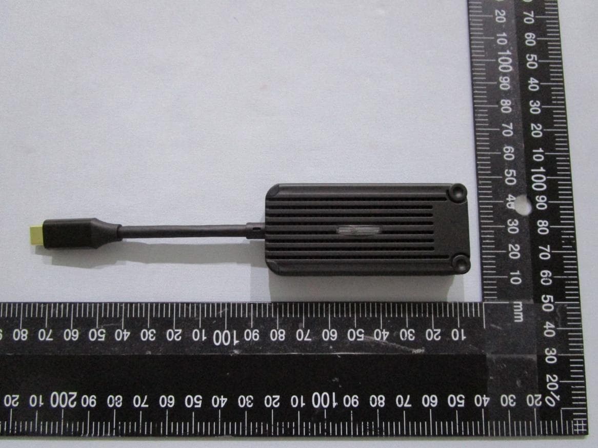
BY4WTR1500C
Sep 18, 2024Wireless HD Transmitter & Receiver Kit
Equipment Class
NII - Unlicensed National Information Infrastructure TX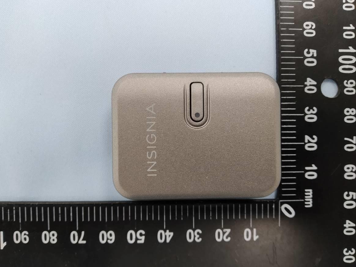
BY4BRX5200A
Sep 25, 2022Portable Bluetooth Wireless Transmitter & Receiver
Equipment Class
DSS - Part 15 Spread Spectrum Transmitter
BY4WFD5000PRO
Jan 17, 20224K UHD Wireless Presentation Receiver
Equipment Class
DTS - Digital Transmission System
BY4WFD1500PRO
Jan 17, 2022Full-HD Wireless Presentation Receiver
Equipment Class
DTS - Digital Transmission System
BY4WTR6000TX
Jul 28, 2021HD Wireless Conference System
Equipment Class
NII - Unlicensed National Information Infrastructure TX