BY4TR2470IR2.4GHz Wireless Audio/Video Sender
Trans Electric Co., Ltd.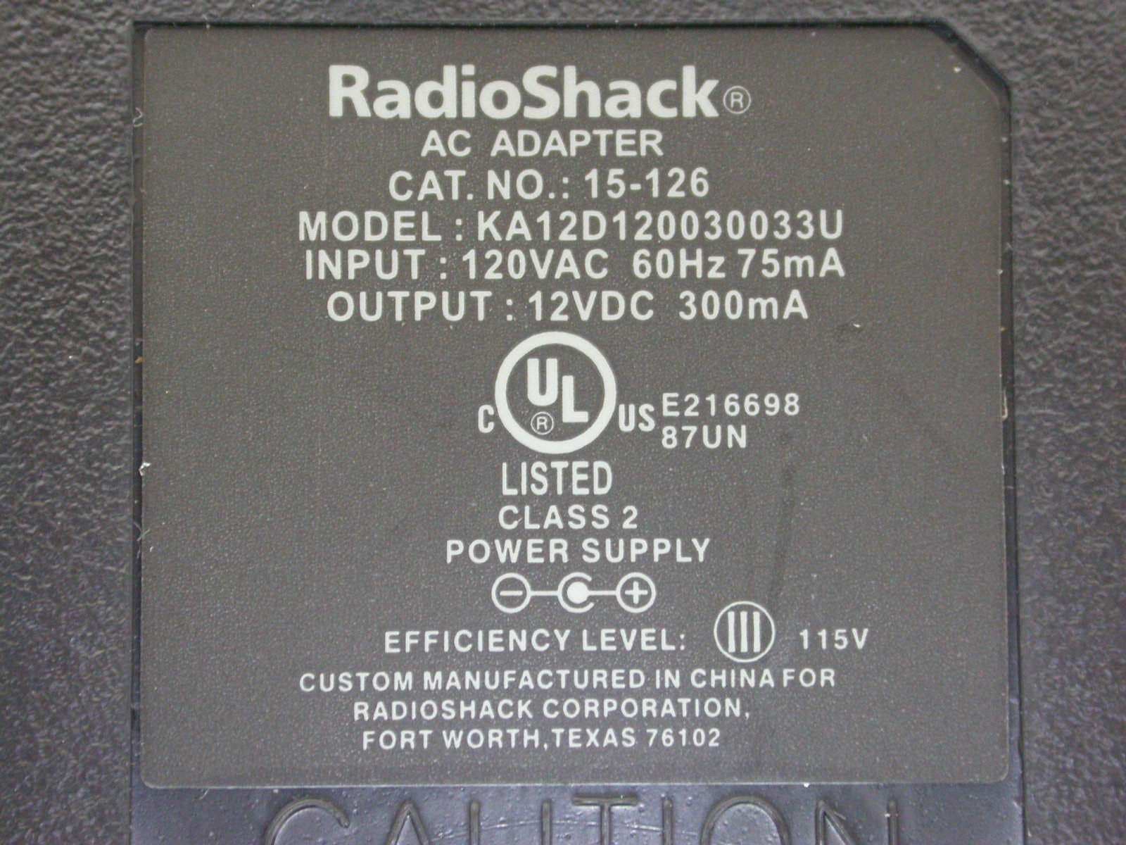
Click to zoom
Application Details
- Equipment Class
- DSR - Part 15 Remote Control/Security Device Transceiver
- Date of Grant
- May 09, 2007
- Application Purpose
- Original Equipment
- Date of Application
- May 09, 2007
- Equipment Note
- 2.4GHz Wireless Audio/Video Sender
- Frequency Range
- 433.92000000 - 433.92000000
- Company
- Trans Electric Co., Ltd.
- Country
- Taiwan
Documents & Files
Document Text
Text extracted from the exhibit documents filed with the FCC. Open a document above to read the original.
Users Manual
2.4GHz Wireless, Audio/Video/S-Video Sender With Built-in Remote Control Extender MODEL: TR-2470 OWNERS MANUAL Made in China TABLE OF CONTENTS ● About the TR-2470 ......................................................................1 ● Location of controls and accessories .........................................2 ● User Guide ......................................................................3 ● Installation .....................................................................4 ● Trouble Shooting ...............................................................5-6 ● Referring Pictures ..................................................................7-9 ● Further applications .............................................................. 10-12 ● Caution ..................................................................13 ● Specification ..................................................................14 ABOUT THE TR-2470 The TR-2470 is a powerful wireless A/V/S-Video signal sender and receiver system which can operate with satellite and cable receivers, camcorders, stereo systems, televisions , laser disc players and VCRs, and provide superior reception at distances of up to 250 feet (clear line of sight) from the transmitter.. And this system can support S-Video This system can be used in many different ways: ● Enables you to watch a movie on any television in your home without moving your VCR or Laser Disc Player, and without the hassle of running wires. ● Enables you to watch your favourite cable or satellite programs on any television in your home. ● Extends the listening enjoyment of your stereo receiver to any powered speakers in your home, even if they are not wired into your stereo system. ● Enables you to use your camcorder with a remote television as a closed circuit monitoring system; ideal for baby's room, or for security. 1 LOCATION OF CONTROLS The TR-2470 has been carefully engineered and manufactured to give you dependable operation. Read this manual before operating this unit to become familiar with its features and obtain the performance that will bring you enjoyment for many years. Please retain this manual for future reference. Transmitter and Transmitter and Transmitter Back Receiver Side Receiver Front Receiver Back ● Transmitter and Receiver 1. Channel Selector 2. 2.4 GHz Antenna 3. ON / OFF Switch 4. AC Adaptor Port ● Transmitter 5. Infrared Remote Output 6. Audio L 7. Audio R 8. Video 9. S-Video 2 ● Receiver 10. Audio L 11. Audio R 12. Video 13. S-Video ● Accessory 1. DC 12V 300mA, AC 110V or 230V Adaptor x 1 (For Transmitter) 2. DC 12V 300mA, AC 110V or 230V Adaptor x 1 (For Receiver) 3. Infrared Extender Mouse x 1 4. A/V Cable x1 Remote Control Indicators DC 12 V AC 120V 300mA Infrared Extender USER GUIDE 1. Make sure your input AC voltage conforms to the adaptor specifications. ( Tolerance never more than 5%, such as 120 VAC +/- 10 VAC ) 2. Only use the power adapter provided with the TR-2470. If you use your own adaptor, make sure the power output is 12V DC, 300 mA centre positive. 3. With direct line-of-sight, the maximum range of A/V signal transmission can reach up to about 250 feet, and this distance would be shortened by obstacles or walls placed between transmitter and receiver. (The optimum indoor range is under 25 M) 4. To ensure good infrared remote control operation aim your remote control at the I/R Sensor Window on the TR 2470 and press the buttons firmly. ( With some remote controls it may be necessary to press and hold each button for about a second). The working angle of the I/R Sensor Window is +/- 15 degrees. (see Pictures 7,8,) 5. The remote controller has to be used within the distance of ( from remote control to receiver )not less than 0.3M and no more than 4.5M (working angle +/- 15 degrees). (see Pictures 9) 6. Be sure the ON / OFF switch on both the transmitter and receiver is in the OFF position before making any connections. 3 INSTALLATION TRANSMITTER (Tx-2470) a. By Composite Video(RCA) 1. Take a RCA to RCA cable(included),take one end connected to the AV In socket of Tx-2470.(see Pictures 1 ) 2. Connect the other end to the Audio / Video Out port of VCR, DVD, VCD, Satellite receiver .Etc. (see Pictures 1) b. by S-Video 1. Take a RCA to RCA cable(included),take Audio RL connected to the Audio RL In socket of Tx-2470. Take a S-Video to S-Video cable connect one end to S-Video input socket of Tx-2470. (see Pictures 1 ) 2.connect the other end of Audio RL to the Audio RL Output Port of VCR, DVD, VCD, Satellite receiver .Etc. and also connect other end of S-video to S-Video Output of of VCR, DVD, VCD, Satellite receiver .Etc. (see Pictures 1 ) 3. Connect the power adaptor to the power outlet. Turn power ON. ** DC 12V 300mA, AC 120V Adaptor. (see Pictures 1 ) 4. Stick the IR mouse in front of the sensor receiving window of the device i.e. VCR, DVD, VCD,.. Satellite receiver . Etc. under effective range and working angles. (see Pictures 2 ) 5. Choose one of the 4 channels by sliding the selection button ( must be set to same Channel on both transmitter & receiver) (see Pictures 4 ) RECEIVER (Rx-2470) a. by Composite Video (RCA) 1. Take a suitable RCA to RCA(included) cable and connect one end to A/V socket of Rx-2470.(see Pictures 3 ) 2. Connect the other end to the Audio / Video In port of TV. (see Pictures 3 ) b. by S-Video 1. Take a RCA to RCA cable(included),take Audio RL connected to the Audio RL In socket of Rx-2470. Take a S-Video to S-Video cable connect one end to S-Video input socket of Rx-2470. (see Pictures 3 ) 2. Connect the other end of Audio RL to the Audio RL Input Port of Television and also connect other end of S-video to S-Video Input Port of Television (see Pictures 3 ) 3. Connect the power adaptor to the power outlet. Turn power ON. **DC 12V 300mA, AC 120V Adaptor (see Pictures 3 ) 4. Choose one of the 4 channels by sliding the selection button ( must be set to same Channel on both transmitter & receiver) (see Pictu…
Text truncated - open the document above for the full version.
External Photos
ETC Report No.: 07-04-MAS-102-02 Page A1 of A3 FCC ID. :BY4TR2470IR ANNEX A: EXTERNAL CONSTRUCTION PHOTOS OF EUT 1. Outside view 1 of EUT 2. Outside view 2 of EUT ETC Report No.: 07-04-MAS-102-02 Page A2 of A3 FCC ID. :BY4TR2470IR 3. Adaptor 4. Adaptor ETC Report No.: 07-04-MAS-102-02 Page A3 of A3 FCC ID. :BY4TR2470IR 5. Adaptor
ID Label/Location Info
ID Label_Location
Internal Photos
ETC Report No.: 07-04-MAS-102-02 Page B1 of B6 FCC ID. :BY4TR2470IR ANNEX B: INTERNAL CONSTRUCTION PHOTOS OF EUT 1. Inside View 1 of EUT 2. Inside View 2 of EUT ETC Report No.: 07-04-MAS-102-02 Page B2 of B6 FCC ID. :BY4TR2470IR 3. Inside View 3 of EUT 4. Inside View 4 of EUT ETC Report No.: 07-04-MAS-102-02 Page B3 of B6 FCC ID. :BY4TR2470IR 5. antenna for 433.96MHz 6. antenna for 2.4GHz ETC Report No.: 07-04-MAS-102-02 Page B4 of B6 FCC ID. :BY4TR2470IR 7. antenna for 2.4GHz ETC Report No.: 07-04-MAS-102-02 Page B5 of B6 FCC ID. :BY4TR2470IR 8. Front view of PCB1 9. Rear view of PCB1 ETC Report No.: 07-04-MAS-102-02 Page B6 of B6 FCC ID. :BY4TR2470IR 10. Front view of PCB2 11. Front view of PCB2
Test Report
ETC Report No. : 07-04-MAS-102-02 Sheet 1 of 29 Sheets FCC ID.: BY4TR2470IR Rev. No 1.0 CONFORMANCE TEST REPORT FOR FCC 47 CFR, Part 15 Subpart B & Subpart C Report No.: 07-04-MAS-102-02 Client: TRANS ELECTRIC CO., LTD. Product: 2.4 GHz Wireless Audio/Video Sender Model: TR-2470(TRANS),15-125R(RadioShack),15-126R(RadioShack) FCC ID: BY4TR2470IR Manufacturer/supplier: TRANS ELECTRIC CO., LTD. Date test item received: 2007/04/16 Date test campaign completed: 2007/05/04 Date of issue: 2007/05/07 The test result only corresponds to the tested sample. It is not permitted to copy this report, in part or in full, without the permission of the test laboratory. Total number of pages of this test report: 29 pages Total number of pages of photos: External photos 3 pages Internal photos 6 pages Setup photos 2 pages Test Engineer Checked By Approved By James James Joe Hsieh ELECTRONICS TESTING CENTER, TAIWAN NO.8, LANE 29, WENMING RD., LESHAN TSUEN, GUISHAN SHIANG, TAOYUAN COUNTY, TAIWAN 33383, R.O.C. TEL: (03) 3276170~4 INT: +886-3-3276170~4 FAX: (03) 3276188 INT: +886-3-3276188 ETC Report No. : 07-04-MAS-102-02 Sheet 2 of 29 Sheets FCC ID.: BY4TR2470IR Rev. No 1.0 Client : TRANS ELECTRIC CO., LTD. Address : 765, Sec.2, Chungsan Rd., Huatang, Changhua, Taiwan, R.O.C. Manufacturer : TRANS ELECTRIC CO., LTD. Address : 765, Sec.2, Chungsan Rd., Huatang, Changhua, Taiwan, R.O.C. EUT : 2.4 GHz Wireless Audio/Video Sender Trade name : TRANS、RadioShack Model No. : TR-2470(TRANS),15-125R(RadioShack),15-126R(RadioShack) Power Source : Adapter Model No.: KA12D120030033U Input: 120Vac, 60Hz, 75mA Output: 12Vdc, 300mA Regulations applied : FCC 47 CFR, Part 15 Subpart B & Subpart C (2006) The testing described in this report has been carried out to the best of our knowledge and ability, and our responsibility is limited to the exercise of reasonable care. This certification is not intended to believe the sellers from their legal and/or contractual obligations. The compliance test is only certified for the test equipment and the results of the testing report relate only to the item tested. The compliance test of this report was conducted in accordance with the appropriate standards. It’s not intention to assure the quality and performance of the product. This report shall not be reproduced except in full, without the approval of ETC. This report must not be used by the client to claim product endorsement by NVLAP or any agency of the U.S. Government. Laboratory Introduction: Electronics Testing Center, Taiwan is recognized, filed and mutual recognition arrangement as following: 1 ISO9001: TüV Product Service 2 ISO/IEC 17025: BSMI, CNLA, DGT, NVLAP, CCIBLAC, UL, Compliance 3 Filing: FCC, Industry Canada, VCCI 4 MRA: Australia, Hong Kong, New Zealand, Singapore, USA, Japan, Korea, China, APLAC through CNLA 5 FCC Registration Number: 90588, 91094, 91095 NVLAP Lab Code 200133-0 ETC Report No. : 07-04-MAS-102-02 Sheet 3 of 29 Sheets FCC ID.: BY4TR2470IR Rev. No 1.0 Table of Contents Page 1. GENERAL INFORMATION ......................................................................................................................................4 1.1 PRODUCT DESCRIPTION.................................................................................................................................................4 1.2 CHARACTERISTICS OF DEVICE:......................................................................................................................................4 1.3 TEST METHODOLOGY....................................................................................................................................................4 1.4 TEST FACILITY...............................................................................................................................................................4 2. DEFINITION AND LIMITS........................................................................................................................................5 2.1 DEFINITION....................................................................................................................................................................5 2.2 RESTRICTED BANDS OF OPERATION...............................................................................................................................5 2.3 LIMITATION....................................................................................................................................................................6 2.4 LABELING REQUIREMENT..............................................................................................................................................7 2.5 USER INFORMATION.......................................................................................................................................................7 3. SYSTEM TEST CONFIGURATION...........................................................................................................................8 3.1 DEVICES FOR TESTED SYSTEM.......................................................................................................................................8 4. RADIATED EMISSION MEASUREMENT..............................................................................................................9 4.1 APPLICABLE STANDARD.................................................................................................................................................9 4.2 MEASUREMENT PROCEDURE.........................................................................................................................................9 4.3 TEST DATA..................................................................................................................................................................11 4.4 FIELD STRENGTH CALCULATION...................................................................................................................…
Text truncated - open the document above for the full version.
Test Setup Photos
ETC Report No. : 07-04-MAS-102-02 Sheet 1 of 2 Sheets FCC ID. :BY4TR2470IR Photos of Radiation Measuring Setup ETC Report No. : 07-04-MAS-102-02 Sheet 2 of 2 Sheets FCC ID. :BY4TR2470IR Photos of Conduction Measuring Setup
Contact Information
Applicant
Grace Wang(Vice-General Manager, Intel' sales Dept.)
Test Firm
Electronics Testing Center, TaiwanWinpo Tsai
Technical Specifications
| # | Rule Parts | Frequency Range | Power Output |
|---|---|---|---|
| 1 | 15.231 | 433.92 MHz - 433.92 MHz | - |
Other Applications from Trans Electric Co., Ltd.
BY4WTR1500C
Sep 18, 2024Wireless HD Transmitter & Receiver Kit
Equipment Class
NII - Unlicensed National Information Infrastructure TX
BY4BRX5200A
Sep 25, 2022Portable Bluetooth Wireless Transmitter & Receiver
Equipment Class
DSS - Part 15 Spread Spectrum Transmitter
BY4WFD5000PRO
Jan 17, 20224K UHD Wireless Presentation Receiver
Equipment Class
DTS - Digital Transmission System
BY4WFD1500PRO
Jan 17, 2022Full-HD Wireless Presentation Receiver
Equipment Class
DTS - Digital Transmission System
BY4WTR6000TX
Jul 28, 2021HD Wireless Conference System
Equipment Class
NII - Unlicensed National Information Infrastructure TX