C6M418TX
Foxpro Inc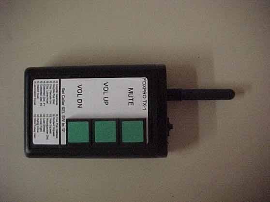
Click to zoom
Application Details
- Equipment Class
- DXX - Part 15 Low Power Communication Device Transmitter
- Date of Grant
- Jun 15, 1999
- Application Purpose
- Original Equipment
- Date of Application
- Apr 21, 1999
- Frequency Range
- 418.05000000 - 418.05000000
- Company
- Foxpro Inc
- Country
- United States
Documents & Files
Document Text
Text extracted from the exhibit documents filed with the FCC. Open a document above to read the original.
Users Manual
FOXPRO Systems 14 Peace Drive Lewistown, PA 17044 (717) 248-2507 REMOTE CONTROL USE Remote System Description The antenna jack is located toward the rear along-side the handle. Plug the antenna in there. A local - remote switch is installed opposite the charge jack. This slide switch, when in the “up” position, selects radio remote operation. When this switch is in the “down” position, the caller can be used in the normal mode of operation. Note that the rear panel selector switch must be set to the “0” position while using remote control. Failure to do this will result in improper operation and will cause increased battery drain. The transmitter is housed in a rugged plastic case, and is powered by a 9-volt battery. Three push- buttons are located on the front panel for Mute, Volume - Up, and Volume - Down. In addition, a BCD push- button switch is located on the top surface to select the sound. A red LED on the top surface illuminates when any of the three push-buttons is depressed. Operation On the caller, set the rear panel selector switch to the “0” position. Place the slide switch to the “up” position. Turn on the caller and set the volume to maximum. On the transmitter, push the “VOL UP” or “VOL DN” to set the volume to the desired level. The sound can be muted or silenced by depressing the “MUTE” button. Push this button again to unmute the sound. To change the sound, first select the appropriate number on the transmitter sound switch, then briefly depress the “VOL UP” push-button. You may also need to press the “MUTE” button as the unit may power up with mute active. Greater range will result if you can elevate the caller by setting it on a rock, a stump, a fence post, or a bush. Maximum range occurs with both antennas vertical. Remember that the rear panel sound selector switch must be in the “ 0” position for proper remote operation. FCC Statement This equipment complies with Part 15 of the FCC Rules. Operation is subject to the following two conditions: (1) this equipment may not cause harmful interference, and (2) this equipment must accept any interference received, including interference that may cause undesired operation. If this equipment does cause harmful interference to radio or television reception, which can be determined by turning the equipment off and on, the user is encouraged to try to correct the interference by one or more of the following measures: * Reorient or relocate the antenna of the radio or television receiver being interfered with. * Increase the separation between the equipment and the radio or television antenna. * Consult the dealer or an experienced radio/television technician for help. The user is cautioned that changes or modifications made to the equipment without the approval of the manufacturer could void the user’s authority to operate this equipment.
Operational Description
FOXPRO Systems 14 Peace Drive Lewistown, PA 17044 (717) 248-2507 SYSTEM DESCRIPTION The TX-1 transmitter is part of a system whereby hunters or photographers use sounds to call animals into close range. The system is comprised of two parts: (1) the main unit, and (2) the transmitter The main unit contains the sound source (which is stored in solid state memory), an audio amplifier, a loudspeaker, and a radio receiver that picks up signals from the TX-1 transmitter that control the sound selection and the volume. This part of the system is powered by four “AA” penlight batteries. The transmitter is a small shirt-pocket sized unit that sends coded signals to the main unit for the purpose of increasing or decreasing the volume, muting the sound, or selecting the sound to be played. Three momentary pushbuttons are located on the front of the transmitter to effect “MUTE”, “VOL UP”, and “VOL DN”. Some models also contain a 16 position BCD pushwheel switch to select from up to 16 different sounds. A standard 9-volt battery powers the transmitter. In use, the main unit would be placed at some distance from the operator, typically from 50 to 200 feet away. The operator would then get into his concealed location and activate the sound with the transmitter. This setup allows the animal to concentrate on the source of the sound without the operator being seen.
Test Report
FCC ID: C6M418TX Report Number: B90111D1 114 OLINDA DRIVE, BREA, CALIFORNIA 92823 PHONE: (714) 579-0500 FAX: (714) 579-1850 Page 2 of 15 TABLE OF CONTENTS Section / TitlePAGE GENERAL REPORT SUMMARY4 SUMMARY OF TEST RESULTS4 1. PURPOSE5 2. ADMINISTRATIVE DATA6 2.1 Location of Testing6 2.2 Traceability Statement6 2.3 Cognizant Personnel6 2.4 Date Test Sample was Received6 2.5 Disposition of the Test Sample6 2.6 Abbreviations and Acronyms6 3. APPLICABLE DOCUMENTS7 4. Description of Test Configuration8 4.1 Description of Test Configuration - EMI8 5. LISTS OF EUT, ACCESSORIES AND TEST EQUIPMENT10 5.1EUT and Accessory List10 5.2 EMI Test Equipment11 6. TEST SITE DESCRIPTION12 6.1 Test Facility Description12 6.2 EUT Mounting, Bonding and Grounding12 7. Test Procedures13 7.1 Radiated Emissions (Spurious and Harmonics) Test13 7.2 Bandwidth of the Fundamental14 8. CONCLUSIONS15 FCC ID: C6M418TX Report Number: B90111D1 114 OLINDA DRIVE, BREA, CALIFORNIA 92823 PHONE: (714) 579-0500 FAX: (714) 579-1850 Page 3 of 15 LIST OF APPENDICES APPENDIXTITLE AModifications to the EUT BAdditional Models Covered Under This Report CDiagrams, Charts and Photos • Test Setup Diagrams • Radiated Emissions Photos • Antenna and Effective Gain Factors DData Sheets LIST OF FIGURES FIGURETITLE 1 Conducted Emissions Test Setup 2 Plot Map And Layout of Test Site FCC ID: C6M418TX Report Number: B90111D1 114 OLINDA DRIVE, BREA, CALIFORNIA 92823 PHONE: (714) 579-0500 FAX: (714) 579-1850 Page 4 of 15 GENERAL REPORT SUMMARY This electromagnetic emission test report is generated by Compatible Electronics Inc., which is an independent testing and consulting firm. The test report is based on testing performed by Compatible Electronics personnel according to the measurement procedures described in the test specifications given below and in the "Test Procedures" section of this report. The measurement data and conclusions appearing herein relate only to the sample tested and this report may not be reproduced in any form unless done so in full with the written permission of Compatible Electronics. This report must not be used to claim product endorsement by NVLAP or any other agency of the U.S. Government. Device Tested:Remote Transmitter Model: TX-1 S/N: N/A Product Description:See Expository Statement. Modifications:The EUT was not modified during the testing. Manufacturer:Penntek Instruments 14 Peace Drive Lewistown, Pennsylvania 17044 Test Date:January 11, 1999 Test Specifications : EMI requirements FCC Title 47, Part 15 Subpart C, Sections 15.205 and 15.231 Test Procedure:ANSI C63.4: 1992 Test Deviations:The test procedure was not deviated from during the testing. SUMMARY OF TEST RESULTS TESTDESCRIPTIONRESULTS 1Conducted RF Emissions, 450 kHz - 30 MHzThis test was not performed because the EUT runs off a nine volt battery only and cannot be powered by any device that runs off of the AC public mains. 2Radiated RF Emissions, 10 kHz - 4200 MHzComplies with FCC Title 47, Part 15 Subpart C, sections 15.205 and 15.231 3-20 dB Bandwidth of the FundamentalComplies with FCC Title 47, Part 15 Subpart C, section 15.231 FCC ID: C6M418TX Report Number: B90111D1 114 OLINDA DRIVE, BREA, CALIFORNIA 92823 PHONE: (714) 579-0500 FAX: (714) 579-1850 Page 5 of 15 1.PURPOSE This document is a qualification test report based on the Electromagnetic Interference (EMI) tests performed on the Remote Transmitter Model: TX-1. The EMI measurements were performed according to the measurement procedure described in ANSI C63.4: 1992. The tests were performed in order to determine whether the electromagnetic emissions from the equipment under test, referred to as EUT hereafter, are within the specification limits defined by FCC Title 47, Part 15, Subpart C, sections 15.205, and 15.231. FCC ID: C6M418TX Report Number: B90111D1 114 OLINDA DRIVE, BREA, CALIFORNIA 92823 PHONE: (714) 579-0500 FAX: (714) 579-1850 Page 6 of 15 2.ADMINISTRATIVE DATA 2.1Location of Testing The EMI tests described herein were performed at the test facility of Compatible Electronics, 114 Olinda Drive, Brea, California 92823. 2.2Traceability Statement The calibration certificates of all test equipment used during the test are on file at the location of the test. The calibration is traceable to the National Institute of Standards and Technology (NIST) . 2.3Cognizant Personnel Penntek Instruments John DillonEngineer Compatible Electronics Inc. Kyle FujimotoTest Engineer Scott McCutchanLab Manager 2.4Date Test Sample was Received The test sample was received on December 22, 1998 2.5Disposition of the Test Sample The test sample was returned to Penntek Instruments on December 30, 1998. 2.6Abbreviations and Acronyms The following abbreviations and acronyms may be used in this document. RFRadio Frequency EMIElectromagnetic Interference EUTEquipment Under Test P/NPart Number S/NSerial Number HPHewlett Packard ITEInformation Technology Equipment CMLCorrected Meter Limit LISNLine Impedance Stabilization Network FCC ID: C6M418TX Report Number: B90111D1 114 OLINDA DRIVE, BREA, CALIFORNIA 92823 PHONE: (714) 579-0500 FAX: (714) 579-1850 Page 7 of 15 3.APPLICABLE DOCUMENTS The following documents are referenced or used in the preparation of this EMI Test Report. SPECTITLE FCC Title 47, Part 15, Subpart C. FCC Rules - Radio frequency devices (including digital devices) – Intentional Radiators. ANSI C63.4 1992 Methods of measurement of radio-noise emissions from low-voltage electrical and electronic equipment in the range of 9 kHz to 40 GHz. FCC ID: C6M418TX Report Number: B90111D1 114 OLINDA DRIVE, BREA, CALIFORNIA 92823 PHONE: (714) 579-0500 FAX: (714) 579-1850 Page 8 of 15 4.DESCRIPTION OF TEST CONFIGURATION 4.1Description of Test Configuration - EMI Setup and operation of the equipment under test. Specifics of the EUT and Peripherals Tested The Remote Transmitter Model: TX-1 (EUT) was tested as a stand alone unit and tested in three different orthogonal axis. The EUT was continuously transmitting during …
Text truncated - open the document above for the full version.
Contact Information
Applicant
John Dillon(President)
Test Firm
Compatible ElectronicsScott McCutchan
714-579-0500Fax: 714-579-1850
Technical Specifications
| # | Rule Parts | Frequency Range | Power Output |
|---|---|---|---|
| 1 | 15C | 418.05 MHz - 418.05 MHz | - |
Other Applications from Foxpro Inc
C6M660
Jul 15, 2015TX915
Equipment Class
DTS - Digital Transmission System
C6M670
Jun 28, 2015Deadbone Transmitter
Equipment Class
DSC - Part 15 Security/Remote Control Transmitter
C6M650
Oct 21, 2014JD1 Transmitter
Equipment Class
DXX - Part 15 Low Power Communication Device Transmitter
C6M621
Sep 28, 2010Foxpro Decoy
Equipment Class
DSC - Part 15 Security/Remote Control Transmitter
C6M619
May 26, 2010Digital Game Caller
Equipment Class
DXT - Part 15 Low Power Transceiver, Rx Verified