C6M670Deadbone Transmitter
Foxpro Inc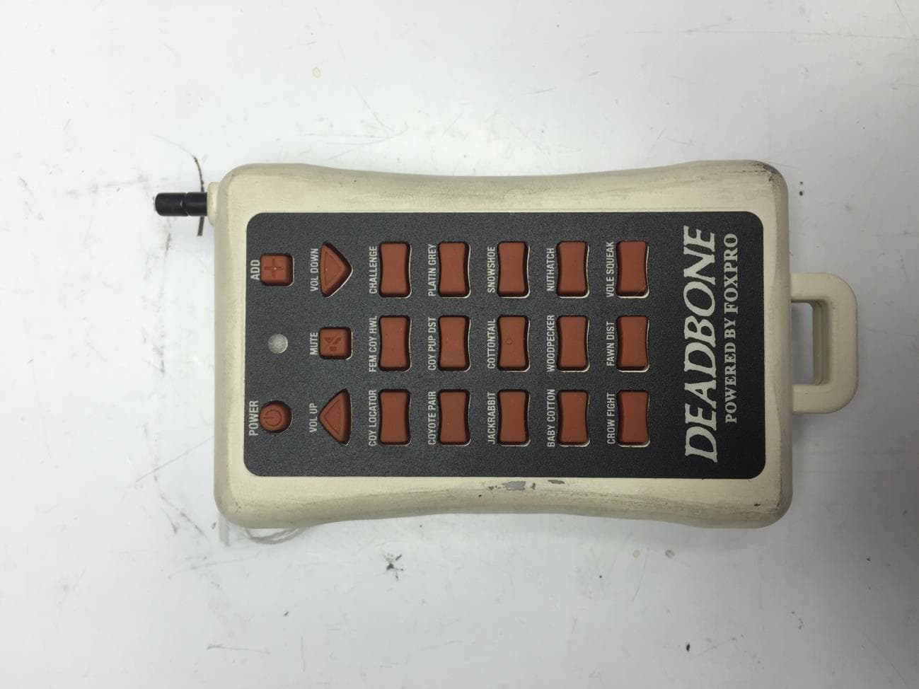
Click to zoom
Application Details
- Equipment Class
- DSC - Part 15 Security/Remote Control Transmitter
- Date of Grant
- Jun 28, 2015
- Application Purpose
- Original Equipment
- Date of Application
- Jun 28, 2015
- Equipment Note
- Deadbone Transmitter
- Frequency Range
- 433.92000000 - 433.92000000
- Company
- Foxpro Inc
- Country
- United States
Documents & Files
Document Text
Text extracted from the exhibit documents filed with the FCC. Open a document above to read the original.
Users Manual
Dead Bone Operators Manual Overview The Dead Bone game call features 15 pro-staff-selected FOXPRO sounds. The sounds that are featured in the Dead Bone include: 1. Coyote Locator 2. Female Coyote Long Howls 3. Female Coyote Challenge Howl 4. Coyote Pair 5. Coyote Pup Distress 3 6. Platinum Grey Fox Pup 7. Lightning Jack 8. Eastern Cottontail 9. Big Baby Cottontail 10. Snow Show High-Pitched 11. Vole Squeaks 12. Wail-N Woodpecker 13. Nutty Nuthatch 14. Crow Fight 15. Whitetail Buck Fawn Distress The Dead Bone is not reprogrammable—meaning that the sounds cannot be changed. General Setup The Dead Bone and Dead Bone transmitter are both sent from the factory without batteries. The first step in getting set up is to install batteries in each device. The Dead Bone requires 4 AA batteries. The batteries fit into a holder located inside of the device (see image on next page). Remove the battery compartment door and insert the 4 AA batteries into the holder while observing correct polarity. Before placing the battery holder back into the Dead Bone, make sure the power wire is connected to the holder. The Dead Bone 2 transmitter conveniently slides into the Dead Bone game call itself. Remove the transmitter from the Dead Bone by sliding it out of its storage compartment. The transmitter requires a single 9V battery. To install the 9V battery, remove the battery door from the rear of the transmitter, connect the battery to the battery connector, and then replace the door. Operation Turning on the Dead Bone Turn on the Dead Bone by moving the power switch to the on position. You will observe the green power indicator illuminating when turned on. If the batteries are getting low, the indicator will begin to blink. Turning on the Dead Bone Transmitter Turn on the Dead Bone transmitter by holding down the power button for about 1-2 seconds. The indicator on the transmitter will illuminate green. When the transmitter begins to get low, the green indicator will flash. Playing a Sound To play a sound, push one of the 15 sound selector buttons a single time. To increase the volume, use the volume up button (to decrease, use volume down). There are 20 volume steps available. The transmitter does not indicate what volume step you are current at during operation. To switch to a different sound, push one of the other sound selector buttons while the current sound is playing. When a sound is playing, it will continue to loop that sound until you either mute it or switch to a different sound. Mute Control To mute the current sound, push the mute button a single time. When muted, the indicator on the transmitter will illuminate red. To un-mute the sound, push the mute button again and the indicator returns to green. Playing Two Sounds Simultaneously Start playing a sound as described previously. Next, push the add button a single time. The indicator switches to an amber color to indicate that it is waiting for you to select the second sound. Push one of the sound selector buttons to activate the second sound. Notice that the indicator returns to green and both sounds will now be playing. When using the mute button while two sounds are playing, be aware that both sounds will mute simultaneously. When you adjust the volume, the volume for both sounds is adjusted simultaneously. To change the second sound, push the add button (indicator turns amber) and then push a 3 different sound selector button. If you have accidentally pushed the add button, just push it a second time to cancel out of that mode. Be aware that if the indicator is green and you push a sound selector button, it will change the original sound and cancel out the second sound at the same time. FCC & Industry Canada Information NOTE: This equipment has been tested and found to comply with the limits for a Class B digital device, pursuant to Part 15 of the FCC Rules. These limits are designed to provide reasonable protection against harmful interference in a residential installation. This equipment generates, uses, and can radiate radio frequency energy and, if not installed and used in accordance with the instructions, may cause harmful interference to radio communications. However, there is no guarantee that the interference will not occur in a particular installation. If this equipment does cause harmful interference to radio or television reception, which can be determined by turning the equipment off and on, the user is encouraged to correct the interference by one or more of the following measures: Reorient or relocate the receiving antenna. Increase the separation between the equipment and receiver. Connect the equipment into an outlet or circuit different that to which the receiver is connected. Consult the dealer or an experienced radio/TV technician for help. Operation is subject to the following two conditions: (1) this device may not cause harmful interference, and (2) this device must accept any interference received, including interference that may cause undesired operation of this device. Modifications not expressly approved by the manufacturer could void the user’s authority to operate the equipment under FCC rules. RF Exposure Safety Notice The Dead Bone transmitter is not intended to be operated closer than 20cm (about 8 inches) to your body. The transmitter can produce a radiated RF field similar to that of a standard cell telephone, although the duty cycle of this RF field is much lower than that of a cell telephone. Using the transmitter closer than 8 inches to your body can increase your exposure to RF energy levels thought by some to be harmful. Additionally, operation in close proximity to your body can detune the antenna causing a decrease in operating performance. The antenna(s) used for this transmitter must be installed to provide a separation distance of at least 20 cm from all persons and must not be co-located or operating in conjunction with any other antenna or transmitter. End-users and installers must be prov…
Text truncated - open the document above for the full version.
ID Label/Location Info
FOXPRO Inc Model: DB1 FCC ID: C6M670 IC: 8027A-670 FOXPRO Inc Model: DB1 FCC ID: C6M670 IC: 8027A-670 This device complies with art 15 of the FCC Rules. Operation is subject to the following two conditions: 1) This device may not cause harmful interference and 2) this device must accept any interference received, including interference that may cause undesired operation. www.gofoxpro.com Made in USAwww.gofoxpro.com Made in USA
Test Report
MET Laboratories, Inc. Safety Certification - EMI - Telecom Environmental Simulation 914 WEST PATAPSCO AVENUE • BALTIMORE, MARYLAND 21230-3432 • PHONE (410) 354-3300 • FAX (410) 354-3313 33439 WESTERN AVENUE • UNION CITY, CALIFORNIA 94587 • PHONE (510) 489-6300 • FAX (510) 489-6372 3162 BELICK STREET • SANTA CLARA, CA 95054 • PHONE (408) 748-3585 • FAX (510) 489-6372 13501 MCCALLEN PASS • AUSTIN, TEXAS 78753 • PHONE (512) 287-2500 • FAX (512) 287-2513 The Nation’s First Licensed Nationally Recognized Testing Laboratory June 5, 2015 Foxpro Inc. 14 Fox Hollow Drive Lewistown, PA 17044 Dear Nathan Smith, Enclosed is the EMC Wireless test report for compliance testing of the Foxpro Inc., Deadbone Transmitter as tested to the requirements of Title 47 of the CFR, Ch. 1 (10-1-06 ed.), FCC Part 15 Subpart C for Intentional Radiators. Thank you for using the services of MET Laboratories, Inc. If you have any questions regarding these results or if MET can be of further service to you, please feel free to contact me. Sincerely yours, MET LABORATORIES, INC. Jennifer Warnell Documentation Department Reference: (\Foxpro Inc.\EMC85603-FCC231) Certificates and reports shall not be reproduced except in full, without the written permission of MET Laboratories, Inc. . MET Laboratories, Inc. Safety Certification - EMI - Telecom Environmental Simulation 914 WEST PATAPSCO AVENUE • BALTIMORE, MARYLAND 21230-3432 • PHONE (410) 354-3300 • FAX (410) 354-3313 33439 WESTERN AVENUE • UNION CITY, CALIFORNIA 94587 • PHONE (510) 489-6300 • FAX (510) 489-6372 3162 BELICK STREET • SANTA CLARA, CA 95054 • PHONE (408) 748-3585 • FAX (510) 489-6372 13501 MCCALLEN PASS • AUSTIN, TEXAS 78753 • PHONE (512) 287-2500 • FAX (512) 287-2513 MET Report: EMC85603-FCC231 © 2015, MET Laboratories, Inc. Page ii of vii Electromagnetic Compatibility Criteria Test Report for the Foxpro Inc. Deadbone Transmitter Tested under the FCC Certification Rules contained in Title 47 of the CFR, Part 15.231 Subpart C for Intentional Radiators MET Report: EMC85603-FCC231 June 5, 2015 Prepared For: Foxpro Inc. 14 Fox Hollow Drive Lewistown, PA 17044 Prepared By: MET Laboratories, Inc. 914 W. Patapsco Ave Baltimore, MD 21230 Electromagnetic Compatibility Foxpro Inc. Cover Letter Deadbone Transmitter CFR Title 47, Part 15.231 MET Report: EMC85603-FCC231 © 2015, MET Laboratories, Inc. Page iii of vii Electromagnetic Compatibility Criteria Test Report for the Foxpro Inc. Deadbone Transmitter Tested under the FCC Certification Rules contained in Title 47 of the CFR, Part 15.231 Subpart C for Intentional Radiators Djed Mouada Jennifer Warnell Project Engineer, Electromagnetic Compatibility Lab Documentation Department Engineering Statement: The measurements shown in this report were made in accordance with the procedures indicated, and the emissions from this equipment were found to be within the limits applicable. I assume full responsibility for the accuracy and completeness of these measurements, and for the qualifications of all persons taking them. It is further stated that upon the basis of the measurements made, the equipment tested is capable of operation in accordance with the requirements of FCC Rules Part 15.231 under normal use and maintenance. Asad Bajwa Director, Electromagnetic Compatibility Lab Electromagnetic Compatibility Foxpro Inc. Report Status Deadbone Transmitter CFR Title 47, Part 15.231 MET Report: EMC85603-FCC231 © 2015, MET Laboratories, Inc. Page iv of vii Report Status Sheet Revision Report Date Reason for Revision June 5, 2015 Initial Issue. Electromagnetic Compatibility Foxpro Inc. Table of Contents Deadbone Transmitter CFR Title 47, Part 15.231 MET Report: EMC85603-FCC231 © 2015, MET Laboratories, Inc. Page v of vii Table of Contents I. Executive Summary .................................................................................................................................................1 A. Purpose of Test ...................................................................................................................................................2 B. Executive Summary ............................................................................................................................................2 II. Equipment Configuration .......................................................................................................................................3 A. Overview .............................................................................................................................................................4 B. References ...........................................................................................................................................................5 C. Test Site ..............................................................................................................................................................5 D. Description of Test Sample .................................................................................................................................5 E. Equipment Configuration ....................................................................................................................................5 F. Mode of Operation ..............................................................................................................................................6 G. Monitoring Method .............................................................................................................................................6 H. Modifications ......................................................................................................................................................6 a) Modifications to EUT .................................................................................................................... 6 b) Modifications to Test Standard..........................................................…
Text truncated - open the document above for the full version.
Test Setup Photos
Photograph 1. Radiated Spurious Emissions, Test Setup, Below 1 GHz Photograph 2. Radiated Spurious Emissions, Test Setup, Above 1 GHz
Contact Information
Applicant
John Dillon(President)
Technical Contact
Foxpro Inc.Nathan Smith
[email protected]717-248-2507
14 Fox Hollow Dr. · Lewistown, Pennsylvania · United States
Non-Technical Contact
Foxpro Inc.John Dillon
[email protected]717-248-2507
Test Firm
EUROFINS ELECTRICAL AND ELECTRONIC TESTING NA, INCGreg Kovolenko
Technical Specifications
| # | Rule Parts | Frequency Range | Power Output |
|---|---|---|---|
| 1 | 15.231 | 433.92 MHz - 433.92 MHz | - |
Other Applications from Foxpro Inc
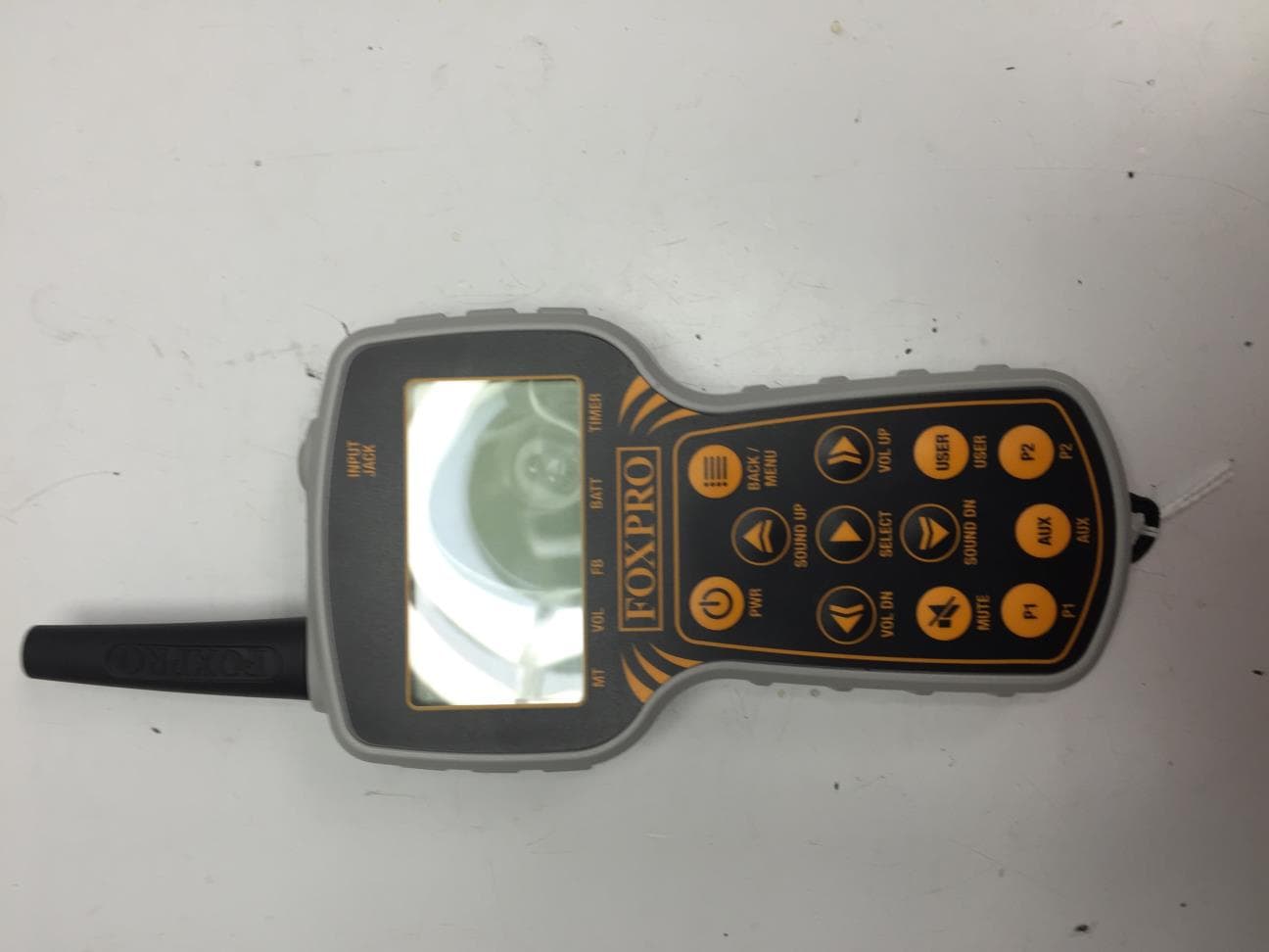
C6M660
Jul 15, 2015TX915
Equipment Class
DTS - Digital Transmission System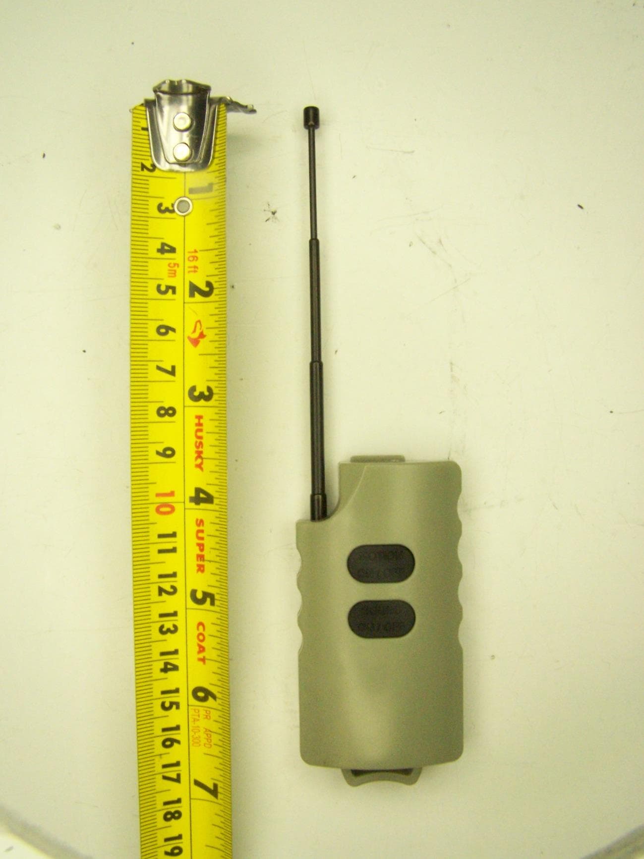
C6M650
Oct 21, 2014JD1 Transmitter
Equipment Class
DXX - Part 15 Low Power Communication Device Transmitter
C6M621
Sep 28, 2010Foxpro Decoy
Equipment Class
DSC - Part 15 Security/Remote Control Transmitter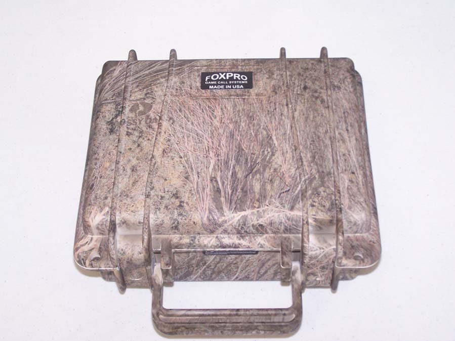
C6M619
May 26, 2010Digital Game Caller
Equipment Class
DXT - Part 15 Low Power Transceiver, Rx Verified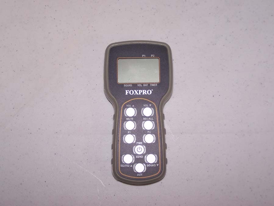
C6M618
May 23, 2010Remote Control Transmitter
Equipment Class
DSC - Part 15 Security/Remote Control Transmitter