C6M650JD1 Transmitter
Foxpro Inc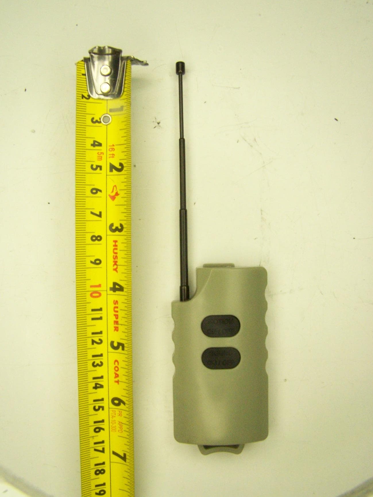
Click to zoom
Application Details
- Equipment Class
- DXX - Part 15 Low Power Communication Device Transmitter
- Date of Grant
- Oct 21, 2014
- Application Purpose
- Original Equipment
- Date of Application
- Oct 21, 2014
- Equipment Note
- JD1 Transmitter
- Frequency Range
- 433.92000000 - 433.92000000
- Company
- Foxpro Inc
- Country
- United States
Documents & Files
Document Text
Text extracted from the exhibit documents filed with the FCC. Open a document above to read the original.
Users Manual
FOXPRO Jack Daddy Operation Instructions To avoid personal injury and prevent product damage, read all operating instructions and safety precautions prior to use. Please note that these instructions may be modified without notice. It is recommended to periodically check the instructions to be aware of any recent changes. Important Information FOXPRO ® ’s goal is to provide our customers with the highest quality products in the industry. We take great pride in manufacturing our products in the USA. Please do not hesitate to contact us for assistance, comments or questions. FOXPRO ® Inc. 14 Fox Hollow Drive Lewistown, PA 17044 (717) 248-2507 Fax: (717) 247-3594 Hours of Operation Monday – Friday 8AM – 5PM EST Contact Us Customer Service: (717) 248-2507 Toll Free Orders Only: 866-463-6977 General Inquiry E-mail: [email protected] This manual, the animal sounds stored in your caller, and animal sounds purchased from FOXPRO ® Inc. for installation in your caller are protected by copyright. Copyright ©℗ 2014 by FOXPRO ® Inc. REV4 - Publication Date: September 10, 2014 2 Jack Daddy Requirements The Jack Daddy is shipped without batteries. The Jack Daddy requires 4 ‘AA’ batteries. Installing batteries in the Jack Daddy 1. Access the battery compartment by removing the door on the back of the Jack Daddy. The door features a knurled thumbscrew for easy access. 2. After the door has been removed, locate the black plastic battery tray. The tray is double-sided, providing spaces for 4 ‘AA’ batteries. The tray can be pulled directly out of the battery compartment. Remove the tray from the compartment. 3. Place the batteries into each battery cavity while observing polarity as indicated. 4. Place the battery tray back into the compartment 5. Secure the door back to the Jack Daddy. Jack Daddy Remote: Requirements The Jack Daddy Remote contains a single lithium coin cell battery (CR2032). To replace the battery, follow the instructions below: 1. Before attempting to replace the battery, it is crucial that you understand the risks of electrostatic discharge potentially harming the electronic board during battery replacement! Prior to replacing the battery, make sure that you are static free. You can touch your hand to a refrigerator door, oven housing, door knob, etc. If you have the ability to use a proper grounding wrist strap, please do so. 2. Carefully separate the Jack Daddy Remote into two halves. This can be accomplished with a flathead screwdriver or other comparable tool. 3. Locate the battery and carefully remove it from the board by sliding it out of the holder. Note battery orientation as you remove it as the new battery must go back in the same way. 4. Carefully slide the new battery into the holder. 5. Place the circuit board back inside the appropriate case half. 6. Line the two halves up together and snap them shut to form a single device once again. Setting Up the Jack Daddy The following instructions apply whether you are using the Jack Daddy as a standalone device or linked-up with a FOXPRO digital game call. Basic field deployment instructions: 1. Locate the mounting stake on the left side of the housing. The Jack Daddy sits upon this stake in the field. 2. Unscrew the mounting stake from the housing. 3. Screw the stake into the mounting point on the bottom of the Jack Daddy. 3 4. Locate the decoy topper support rod on the right side of the housing. The rod is removed by pulling it straight up. Note: there is a plastic decoy support rod alignment piece that holds the rod in place. You may need to free this piece prior to pulling out the rod. 5. Place the bird on the top of the rod by sliding it down and over the tip. 6. Secure the bottom of the rod to the Jack Daddy by inserting it into the receptacle on the top of the Jack Daddy and snapping the plastic decoy support rod alignment piece in place at the base. 7. Remove the Jack Daddy Remote from the back of the Jack Daddy by pulling it straight out of its compartment. Powering On the Jack Daddy 1. Locate the power switch on the front of the Jack Daddy. Notice that it has 3 positions. From left to right: On, Off, On w/ LED. The difference between “On” and “On w/ LED” is that “On w/ LED” results in the LED illuminating when powered on. 2. Slide the switch into the desired position to turn on the power. If you selected “On w/ LED” you will notice the LED illuminate. Toggling Decoy Motion 1. Make sure the Jack Daddy is powered on. 2. The Jack Daddy Remote features two buttons. The bottom button is for toggling the decoy motion on and off. 3. To activate decoy motion: push the bottom button a single time. To deactivate: push the button a second time. Playing a Sound 1. Make sure the Jack Daddy is powered on. 2. To the right of the power switch is the sound selector switch. This switch has three positions labeled 1, 2, and 3. Each position represents a single sound. Sound 1 is a FOXPRO Sound “L54 Bay Bee Cottontail”. Sound 2 is a FOXPRO Sound “R07 Vole Squeaks”. Sound 3 is FOXPRO Sound “B04 Worried Woodpecker”. Move the switch into the desired position. 3. The Jack Daddy Remote features two buttons. The top button is for toggling the sound on and off. 4. To play the selected sound: push the top button a single time. To stop playing the sound: push the button a second time. 5. To change the sound, move the sound selector switch to one of the other positions. You cannot change the sound from the remote control. 4 Connecting to a FOXPRO Game Call You can connect the Jack Daddy to an existing FOXPRO game call to use it strictly as a decoy. When connecting it to a FOXPRO game call, the Jack Daddy will not produce any sound. 1. Connect a 3.5 mm stereo cable from the jack on the Jack Daddy to the auxiliary jack on your FOXPRO game call. 2. Power on the Jack Daddy to your desired state (with or without LED). 3. Turn on your FOXPRO game call. 4. Use the AUX button on your FOXPRO game call remote to toggle the Jack Daddy decoy motion on and off. FCC …
Text truncated - open the document above for the full version.
Cover Letter(s)
FOXPRO INC. 14 Fox Hollow Drive Lewistown, PA 17044 (717)248-2507 FAX(717)247-3594 www.gofoxpro.com September 4, 2014 MET Laboratories, Inc. 914 West Patapsco Avenue Baltimore, MD 21230 RE: CONFIDENTIALITY REQUEST FOR FOXPRO JACK DADDY FCC ID: C6M650 To Whom It May Concern: This letter serves as an official request for confidentiality under sections 0.457 and 0.459 of CFR 47. We have requested that the schematics, block diagrams, BOMs, and operational descriptions required to be submitted with this application be permanently withheld from public view. These items would be privileged as a matter of law if retained by the person submitting them, and are materials which would not customarily be released to the public by that person. If you have any questions or need additional information, please give me a call at 717-248-2507. Sincerely, John Dillon, President
Test Report
MET Laboratories, Inc. Safety Certification - EMI - Telecom Environmental Simulation 914 WEST PATAPSCO AVENUE • BALTIMORE, MARYLAND 21230-3432 • PHONE (410) 354-3300 • FAX (410) 354-3313 33439 WESTERN AVENUE • UNION CITY, CALIFORNIA 94587 • PHONE (510) 489-6300 • FAX (510) 489-6372 3162 BELICK STREET • SANTA CLARA, CA 95054 • PHONE (408) 748-3585 • FAX (510) 489-6372 13301 MCCALLEN PASS • AUSTIN, TEXAS 78753 • PHONE (512) 287-2500 • FAX (512) 287-2513 The Nation’s First Licensed Nationally Recognized Testing Laboratory October 14, 2014 Foxpro Inc. 14 Fox Hollow Drive Lewistown, PA 17044 Dear Chuck Eversole, Enclosed is the EMC Wireless test report for compliance testing of the Foxpro Inc., JackDaddy Transmitter; Model JD1 as tested to the requirements of Title 47 of the CFR, Ch. 1 (10-1-06 ed.), FCC Part 15 Subpart B and ICES-003 Issue 5, August 2012 for a Class B Digital Device and FCC Part 15 Subpart C and RSS-210 Issue 8, December 2010 for Intentional Radiators. Thank you for using the services of MET Laboratories, Inc. If you have any questions regarding these results or if MET can be of further service to you, please feel free to contact me. Sincerely yours, MET LABORATORIES, INC. Jennifer Warnell Documentation Department Reference: (\Foxpro Inc.\EMC42212-FCC231) Certificates and reports shall not be reproduced except in full, without the written permission of MET Laboratories, Inc. . MET Laboratories, Inc. Safety Certification - EMI - Telecom Environmental Simulation 914 WEST PATAPSCO AVENUE • BALTIMORE, MARYLAND 21230-3432 • PHONE (410) 354-3300 • FAX (410) 354-3313 33439 WESTERN AVENUE • UNION CITY, CALIFORNIA 94587 • PHONE (510) 489-6300 • FAX (510) 489-6372 3162 BELICK STREET • SANTA CLARA, CA 95054 • PHONE (408) 748-3585 • FAX (510) 489-6372 13301 MCCALLEN PASS • AUSTIN, TEXAS 78753 • PHONE (512) 287-2500 • FAX (512) 287-2513 MET Report: EMC42212-FCC231 © 2014, MET Laboratories, Inc. Page ii of vii Electromagnetic Compatibility Criteria Test Report for the Foxpro Inc. JackDaddy Transmitter; Model JD1 Tested under the FCC Certification Rules contained in Title 47 of the CFR, Parts 15 Subpart B and ICES-003 for Class A Digital Devices & 15.231 Subpart C and RSS-210 for Intentional Radiators MET Report: EMC42212-FCC231 October 14, 2014 Prepared For: Foxpro Inc. 14 Fox Hollow Drive Lewistown, PA 17044 Prepared By: MET Laboratories, Inc. 914 W. Patapsco Ave Baltimore, MD 21230 Electromagnetic Compatibility Foxpro Inc. Cover Letter JackDaddy Transmitter; Model JD1 CFR Title 47, Part 15B, 15.231 & ICES-003, RSS-210 MET Report: EMC42212-FCC231 © 2014, MET Laboratories, Inc. Page iii of vii Electromagnetic Compatibility Criteria Test Report for the Foxpro Inc. JackDaddy Transmitter; Model JD1 Tested Under the FCC Certification Rules contained in Title 47 of the CFR, Parts 15 Subpart B and ICES-003 for Class A Digital Devices & 15.231 Subpart C and RSS-210 for Intentional Radiators Benjamin Taylor, Project Engineer Jennifer Warnell Electromagnetic Compatibility Lab Documentation Department Engineering Statement: The measurements shown in this report were made in accordance with the procedures indicated, and the emissions from this equipment were found to be within the limits applicable. I assume full responsibility for the accuracy and completeness of these measurements, and for the qualifications of all persons taking them. It is further stated that upon the basis of the measurements made, the equipment tested is capable of operation in accordance with the requirements of FCC Rules Parts 15B and 15.231 and Industry Canada standards ICES-003 Issue 5, August 2012 and RSS-210 Issue 8, December 2010 under normal use and maintenance. Asad Bajwa Director, Electromagnetic Compatibility Lab Electromagnetic Compatibility Foxpro Inc. Report Status JackDaddy Transmitter; Model JD1 CFR Title 47, Part 15B, 15.231 & ICES-003, RSS-210 MET Report: EMC42212-FCC231 © 2014, MET Laboratories, Inc. Page iv of vii Report Status Sheet Revision Report Date Reason for Revision October 14, 2014 Initial Issue. Electromagnetic Compatibility Foxpro Inc. Table of Contents JackDaddy Transmitter; Model JD1 CFR Title 47, Part 15B, 15.231 & ICES-003, RSS-210 MET Report: EMC42212-FCC231 © 2014, MET Laboratories, Inc. Page v of vii Table of Contents I. Executive Summary .................................................................................................................................................1 A. Purpose of Test ...................................................................................................................................................2 B. Executive Summary ............................................................................................................................................2 II. Equipment Configuration .......................................................................................................................................3 A. Overview .............................................................................................................................................................4 B. References ...........................................................................................................................................................4 C. Test Site ..............................................................................................................................................................5 D. Description of Test Sample .................................................................................................................................5 E. Equipment Configuration ....................................................................................................................................5 F. Mode of Operation ..............................................................................................................................................6 G. Monitoring Method ...............…
Text truncated - open the document above for the full version.
Test Setup Photos
Photograph 1. Radiated Emission, Test Setup
Contact Information
Applicant
John Dillon(President)
Technical Contact
Foxpro Inc.Nathan J. Smith
[email protected]707-248-2507
14 Fox Hollow Dr. · Lewistown, Pennsylvania · United States
Non-Technical Contact
Foxpro Inc.John Dillon
[email protected]717-248-2507
Test Firm
EUROFINS ELECTRICAL AND ELECTRONIC TESTING NA, INCGreg Kovolenko
Technical Specifications
| # | Rule Parts | Frequency Range | Power Output |
|---|---|---|---|
| 1 | 15C | 433.92 MHz - 433.92 MHz | - |
Other Applications from Foxpro Inc
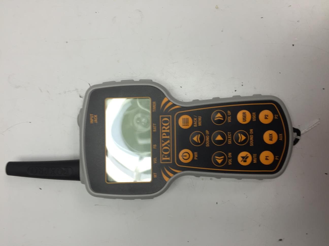
C6M660
Jul 15, 2015TX915
Equipment Class
DTS - Digital Transmission System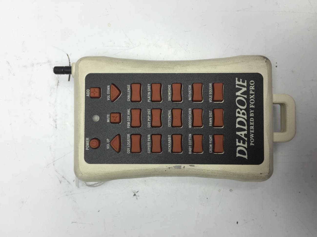
C6M670
Jun 28, 2015Deadbone Transmitter
Equipment Class
DSC - Part 15 Security/Remote Control Transmitter
C6M621
Sep 28, 2010Foxpro Decoy
Equipment Class
DSC - Part 15 Security/Remote Control Transmitter
C6M619
May 26, 2010Digital Game Caller
Equipment Class
DXT - Part 15 Low Power Transceiver, Rx Verified
C6M618
May 23, 2010Remote Control Transmitter
Equipment Class
DSC - Part 15 Security/Remote Control Transmitter