CASTBAC0Base Station Transceiver
Tait International Limited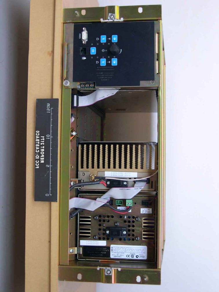
Click to zoom
Application Details
- Equipment Class
- TNB - Licensed Non-Broadcast Station Transmitter
- Date of Grant
- Apr 06, 2005
- Application Purpose
- Original Equipment
- Date of Application
- Apr 06, 2005
- Equipment Note
- Base Station Transceiver
- Frequency Range
- 220.00000000 - 222.00000000
- Company
- Tait International Limited
- Country
- New Zealand
Documents & Files
Document Text
Text extracted from the exhibit documents filed with the FCC. Open a document above to read the original.
Users Manual
TB8100 Installation and Operation ManualInstallation59 © Tait Electronics Ltd March 2004 5Installation This chapter describes how to install the TB8100 BSS in a standard 19 inch rack or cabinet. It also provides some general information on safety precautions and site requirements. We recommend that you read the entire chapter before beginning the installation. 5.1Personal Safety Lethal Voltages Warning!!The PMU contains voltages that may be lethal. Refer to the ratings label on the rear of the module. The TB8100 BSS must be installed so that the rear of the PMU is located in a service access area. Disconnect the mains IEC connector and wait for five minutes for the internal voltages to self-discharge before dismantling. The AC power on/off switch does not isolate the PMU from the mains. It breaks only the phase circuit, not the neutral. The PMU should be serviced only by qualified technicians. All servicing should be carried out only when the PMU is powered through a mains isolating transformer of sufficient rating. We strongly recommend that the mains power to the whole of the repair and test area is supplied via an earth leakage circuit breaker. Explosive Environments Warning!!Do not operate TB8100 BSS equipment near electrical blasting caps or in an explosive atmos- phere. Operating the equipment in these envi- ronments is a definite safety hazard. Proximity to RF Transmissions Do not operate the transmitter when someone is standing within 90 cm (3ft) of the antenna. Do not operate the transmitter unless you have checked that all RF connectors are secure. 60InstallationTB8100 Installation and Operation Manual © Tait Electronics Ltd March 2004 High Temperatures Take care when handling a PMU or PA which has been operating recently. Under extreme operating conditions (+ 60° C [+140° F] ambient air temperature) or high duty cycles the external surfaces of the PMU and PA can reach temperatures of up to + 80°C (+176°F). 5.2Equipment Safety ESD Precautions ImportantThis equipment contains devices which are susceptible to damage from static charges. You must handle these devices carefully and according to the procedures described in the manufacturers’ data books. We recommend you purchase an antistatic bench kit from a reputable manufacturer and install and test it according to the manufacturer’s instructions. Figure 5.1 shows a typical antistatic bench set-up. You can obtain further information on antistatic precautions and the dangers of electrostatic discharge (ESD) from standards such as ANSI/ESD S20.20-1999 or BS EN 100015-4 1994. Aerial Load The TB8100 BSS equipment has been designed to operate safely under a wide range of aerial loading conditions. However, we strongly recommend that the transmitter should always be operated with a suitable load to prevent damage to the transmitter output power stage. Figure 5.1Typical Antistatic Bench Set-up common point ground (building ground or mains ground via 1 M ohm series resistor) conductive wrist strapdissipative rubber bench mat TB8100 Installation and Operation ManualInstallation61 © Tait Electronics Ltd March 2004 Equipment Grounding To ensure safe operation the TB8100 BSS equipment must be correctly grounded as described in these installation instructions. Installation and Servicing Personnel The TB8100 BSS should be installed and serviced only by qualified personnel. 5.3Regulatory Information Distress Frequencies The 406 to 406.1MHz frequency range is reserved worldwide for use by Distress Beacons. Do not program transmitters to operate in this frequency range. FCC Compliance This device complies with part 15 of the FCC Rules. Operation is subject to the condition that this device does not cause harmful interference. Unauthorised Modifications Any modifications you make to this equipment which are not authorised by Tait Electronics Ltd may invalidate your compliance authority’s approval to operate the equipment. 5.4Environmental Conditions Operating Temperature Range The operating temperature range of the TB8100 BSS is – 30°C to +60°C (–22°F to + 140°F) ambient temperature. Ambient temperature is defined as the temperature of the air at the intake to the cooling fans. Humidity The humidity should not exceed 95% relative humidity through the specified operating temperature range. 62InstallationTB8100 Installation and Operation Manual © Tait Electronics Ltd March 2004 Dust and Dirt For uncontrolled environments, the level of airborne particulates must not exceed 100 μg/m 3 . 5.5Grounding and Lightning Protection Electrical Ground The TB8100 BSS modules are grounded by physical contact between the module case and the subrack. To ensure a good ground connection you must tighten each module retaining clamp securely (refer to “Final Reassembly” on page 81 for the correct torque setting). A threaded grounding connector is provided on the rear of the subrack for connection to the site ground point (refer to “Connection” on page 83 for more details). Lightning Ground It is extremely important for the security of the site and its equipment that you take adequate precautions against lightning strike. While it is outside the scope of this manual to provide comprehensive information on this subject, the following guidelines apply: ■install a suitable lightning rod at the top of the tower and connect it to a secure ground point with appropriate conductors and connectors ■position site buildings and equipment within the cone of protection provided by the grounded tower ■protect all cables entering the site to prevent lightning energy from entering site buildings. 5.6Recommended Tools It is beyond the scope of this manual to list every tool that an installation technician should carry. However, the following tools are specifically required for installing the TB8100 BSS: ■Pozidriv PZ3 screwdriver for the M6 screws used to secure the subrack to the rack or cabinet, and also for the DC input terminals on the PMU ■Pozidriv PZ2 screwdriver for the M4 screws …
Text truncated - open the document above for the full version.
Users Manual
MB8100-00-00-742 June 2004 TB8100 base station Specifications Manual 2TB8100 Specifications Manual © Tait Electronics Ltd June 2004 Tait Contact Information Tait Radio Communicationshttp:// www.taitworld.com Corporate Head Office New Zealand Tait Electronics Ltd P.O. Box 1645 Christchurch New Zealand E-mail: [email protected] We b s i t e : http://www.taitworld.com Technical Support: E-mail: [email protected] We b s i t e : http://support.taitworld.com Tait North America Regional Head Office - United States of America Tait North America Inc. E-mail: [email protected] Canada Tait North America Inc. E-mail: [email protected] Latin America Tait Latin America E-mail: [email protected] Tait Europe Regional Head Office - United Kingdom Tait Mobile Radio Ltd E-mail: [email protected] Tait North Asia Regional Head Office - Hong Kong Tait Mobile Radio (Hong Kong) Ltd E-mail: [email protected] Beijing Tait Mobile Radio (Hong Kong) Ltd E-mail: [email protected] Tait South Asia Regional Head Office - Singapore Tait Electronics (Far East) Pte Ltd E-mail: [email protected] Thailand Tait Mobile Radio Ltd E-mail: [email protected] Oceania New Zealand Tait Communications Ltd E-mail: [email protected] Australia Tait Electronics (Aust) Pty Ltd E-mail: [email protected] Note: For the addresses and phone numbers of the above regional offices refer to the TaitWorld website. TB8100 Specifications Manual3 © Tait Electronics Ltd June 2004 Contents Preface . . . . . . . . . . . . . . . . . . . . . . . . . . . . . . . . . . . . . . . . . . . . . . . . . 5 Scope of Manual. . . . . . . . . . . . . . . . . . . . . . . . . . . . . . . . . . . . . . . . . . . . . . . . . 5 Enquiries and Comments . . . . . . . . . . . . . . . . . . . . . . . . . . . . . . . . . . . . . . . . . . 5 Updates of Manual and Equipment . . . . . . . . . . . . . . . . . . . . . . . . . . . . . . . . . . . 5 Copyright. . . . . . . . . . . . . . . . . . . . . . . . . . . . . . . . . . . . . . . . . . . . . . . . . . . . . . 5 Disclaimer . . . . . . . . . . . . . . . . . . . . . . . . . . . . . . . . . . . . . . . . . . . . . . . . . . . . . 5 Associated Documentation . . . . . . . . . . . . . . . . . . . . . . . . . . . . . . . . . . . . . . . . . 6 1 System Specifications . . . . . . . . . . . . . . . . . . . . . . . . . . . . . . . . . . . . . 7 Transmit Power and Current Consumption - 240 VAC Input . . . . . . . . . . . . . . . 8 Transmit Power and Current Consumption - 110 VAC Input . . . . . . . . . . . . . . . 8 Transmit Power and Current Consumption - AC Input Voltage Extremes . . . . . 9 Transmit Power and Current Consumption - 12.5VDC Input . . . . . . . . . . . . . . 9 Transmit Power and Current Consumption - DC Input Voltage Extremes . . . . 10 Receive Power and Current Consumption . . . . . . . . . . . . . . . . . . . . . . . . . . . 10 Dimensions and Weight . . . . . . . . . . . . . . . . . . . . . . . . . . . . . . . . . . . . . . . . . 11 Isolation . . . . . . . . . . . . . . . . . . . . . . . . . . . . . . . . . . . . . . . . . . . . . . . . . . . . . 11 2 Reciter Specifications . . . . . . . . . . . . . . . . . . . . . . . . . . . . . . . . . . . . 13 General . . . . . . . . . . . . . . . . . . . . . . . . . . . . . . . . . . . . . . . . . . . . . . . . . . . . . 15 Receiver RF Section . . . . . . . . . . . . . . . . . . . . . . . . . . . . . . . . . . . . . . . . . . . 16 Receiver Audio Section - General . . . . . . . . . . . . . . . . . . . . . . . . . . . . . . . . . . 19 Receiver Audio Section - CTCSS . . . . . . . . . . . . . . . . . . . . . . . . . . . . . . . . . . 20 Receiver Audio Section - Gating Operation . . . . . . . . . . . . . . . . . . . . . . . . . . 20 Exciter RF Section . . . . . . . . . . . . . . . . . . . . . . . . . . . . . . . . . . . . . . . . . . . . . 21 Exciter Audio Section - Inputs . . . . . . . . . . . . . . . . . . . . . . . . . . . . . . . . . . . . 21 Exciter Audio Section - Modulation Characteristics . . . . . . . . . . . . . . . . . . . . . 22 Exciter Audio Section - CTCSS . . . . . . . . . . . . . . . . . . . . . . . . . . . . . . . . . . . 23 External Reference Input . . . . . . . . . . . . . . . . . . . . . . . . . . . . . . . . . . . . . . . . 23 Compliance Standards . . . . . . . . . . . . . . . . . . . . . . . . . . . . . . . . . . . . . . . . . . . 23 3 Power Amplifier and Transmitter Specifications . . . . . . . . . . . . . . . . . 25 General . . . . . . . . . . . . . . . . . . . . . . . . . . . . . . . . . . . . . . . . . . . . . . . . . . . . . 27 Power Amplifier RF Section . . . . . . . . . . . . . . . . . . . . . . . . . . . . . . . . . . . . . . 28 Transmitter RF Section. . . . . . . . . . . . . . . . . . . . . . . . . . . . . . . . . . . . . . . . . . 29 Control and Monitoring . . . . . . . . . . . . . . . . . . . . . . . . . . . . . . . . . . . . . . . . . 30 Compliance Standards . . . . . . . . . . . . . . . . . . . . . . . . . . . . . . . . . . . . . . . . . . . 31 4TB8100 Specifications Manual © Tait Electronics Ltd June 2004 4 Power Management Unit Specifications . . . . . . . . . . . . . . . . . . . . . . . 33 General . . . . . . . . . . . . . . . . . . . . . . . . . . . . . . . . . . . . . . . . . . . . . . . . . . . . . 34 Input - AC Module . . . . . . . . . . . . . . . . . . . . . . . . . . . . . . . . . . . . . . . . . . . . 34 Input - DC Module . . . . . . . . . . . . . . . . . . . . . . . . . . . . . . . . . . . . . . . . . . . . 35 Output - AC and DC Modules . . . . . . . . . . . . . . . . . . . . . . . . . . . . . . . . . . . . 36 Optional 10W Standby Output - DC Module . . . . . . . . . . . . . . . . . . . . . . . . . 36 Optional 40W Auxiliary Power Supply . . . . . . . . . . . . . . . . . . . . . . . . . . . . . . 37 Connections. . . . . . . . . . . . . . . . . . . . . . . . . . . . . . . . . . . . . . . . . . . . . . . . . . 37 Compliance Standards. . . . . . . . . . . . . . . . . . . . . . . . . . . . . . . . . …
Text truncated - open the document above for the full version.
Cover Letter(s)
FCC ID: [CASTBAC0] Request for Confidentiality In accordance with 47 C.F.R. Section 0.459, we, (Tait Electronics Limited), hereby request confidentiality for the [Schematics, Block Diagrams, Operational Description, and Parts Lists] presented for certification. In support of the Request for Confidentiality, the following is stated: Enclosed within this application is technical information which we deem to be trade secrets and proprietary. If made public, the information might be used to our disadvantage. To assist in assuring that we receive the full value of our product and protect its competitive posture, we respectfully request this grant of confidentiality. [Steve Crompton] [Tait Electronics Limited]
Parts List/Tune Up Info
Calibration Kit User’s Manual MB8100-90-00-806 March 2004 TB8100 base station TB8100 Calibration Kit User’s ManualContents i Contents Preface ..............................................................................................................iii Enquiries and Comments ..................................................................iii Updates of Manual and Equipment ...................................................iii Copyright .........................................................................................iii Disclaimer ........................................................................................iii Typographical Conventions ..............................................................iii Associated Documentation ...............................................................iii Publication Record ..........................................................................iv About TB8100 Calibration Kit ...........................................................................5 Tour of TB8100 Calibration Kit .............................................................5 About the Toolbar ............................................................................6 About the Status Bar ..........................................................................6 Basic Tasks .........................................................................................................7 Equipment Required ..............................................................................7 Tuning Tool .....................................................................................8 Reciter Tuning Holes .............................................................................8 Holes for Tuning the Receiver VCO and Exciter VCO ....................8 Holes for Tuning the Receiver Front-End .........................................8 Configuring TB8100 Calibration Kit ......................................................9 Selecting the Communications Port ...................................................9 Connecting to the Base Station ............................................................. 10 Connecting to the Reciter Outside the Subrack .............................. 11 Connecting to the Reciter/PA in the Subrack ................................. 12 Disconnecting from the Base Station/Reciter ....................................... 12 Basic Troubleshooting .......................................................................... 13 Adjusting the Frequency Setup ......................................................................15 Adjusting the Receiver Lock Band ....................................................... 15 Tuning the Receiver ............................................................................ 16 Adjusting the Exciter Lock Band .......................................................... 17 Calibrating the Reciter ....................................................................................19 Calibrating the Exciter .......................................................................... 19 Automatically Tune the Frequency Control Loop (FCL) ................. 19 Calibrating the FCL Modulation ..................................................... 20 Calibrating the VCO Modulation .................................................... 21 Calibrating the RSSI ............................................................................. 22 Audio Calibration ................................................................................. 23 Calibrating the Balanced Lines ......................................................... 23 Calibrating the Unbalanced Lines .................................................... 24 Calibrating the TCXO ......................................................................... 25 ii ContentsMB8100-90-00-806 © TEL 2004 Calibrating the Power Amplifier ................................................................... 27 Calibrating the PA Bias ........................................................................ 27 Calibrating the PA Power .................................................................... 28 Troubleshooting Tips ..................................................................... 29 Calibrating the Forward and Reverse Detector Bias Voltages ............... 29 Index .................................................................................. 31 TB8100 Calibration Kit User’s Manual Preface iii Preface Welcome to the TB8100 Calibration Kit User’s Manual. This manual provides you with information about the Tait TB8100 Calibration Kit in PDF format. You can view it online or print it if you want a paper copy. It describes how to use Version 02.00 of the Calibration Kit. Enquiries and Comments Any enquiries regarding this manual as well as any comments, suggestions and notifications of errors should be sent to [email protected], or addressed to the Support Group Manager, Tait Electronics Limited, PO Box 1645 Christchurch, New Zealand. Updates of Manual and Equipment In the interests of improving the performance, reliability or servicing of the equipment, Tait Electronics Limited reserves the right to update the equipment or this manual or both without prior notice. Copyright All information contained in this manual is the property of Tait Electronics Limited. All rights are reserved. This manual may not, in whole or in part, be copied, photocopied, reproduced, translated, stored, or reduced to any electronic medium or machine-readable form, without prior written permission from Tait Electronics Limited. All trade names referenced are the service mark, trademark or registered trademark of the respective manufacturers. Disclaimer There are no warranties extended or granted by this manual. Tait Electronics Limited accepts no responsibility for damage arising from use of the information contained in the manual or of the equipment and software it describes. It is the respons…
Text truncated - open the document above for the full version.
Test Report
TELTEST Laboratories Tait Electronics Limited Report Number 2171 FCC ID: CASTBAC0 Page 1 of 60 REPORT NUMBER 2171February 2005 RADIO PERFORMANCE MEASUREMENTS On the TBAC0Base Station Transceiver FCC ID: CASTBAC0 Comprising of: FUNCTIONAL DESCRIPTION PRODUCT DESIGNATION CODE SERIAL NUMBER Reciter TBA40C2-0B0018005716 Power Amplifier TBA90C0-0000 TBA80C0-0000 TBA70C0-0000 18004873 18005083 18005074 Power Management Unit TBA30A1-1100 TBA30A0-0000 18004274 18004653 High Stability Oscillator T801-20-00013122298 In accordance with FCC 47 CFR Parts 90T, and 90.259 PREPARED BY:Marcus Ludwig ___________________ Test Technician CHECKED & APPROVED BY:Hamish Newton___________________ Senior Technician TELTEST Laboratories Tait Electronics Limited PO Box 1645 558 Wairakei Road Christchurch New Zealand Phone : (64) (3) 3583399 Fax: (64) (3) 3580432 TELTEST Laboratories Tait Electronics Limited Report Number 2171 FCC ID: CASTBAC0 Page 2 of 60 REPORT ON : Type Approval Testing of the TBAC0 in accordance with: FCC CFR 47 Parts 90T, and 90.259 FCC ID: CASTBAC0 PREPARED FOR : Tait Electronics Ltd PO Box 1645 558 Wairakei Rd Christchurch New Zealand DISTRIBUTION : TELTest LaboratoryMr S CromptonCopy No 1 Tait Electronics LtdMr. Des Fox Copy No 2 Tait Electronics LtdMr. Ian MacKayCopy No 3 APPROVED : Hamish Newton Senior Technician Date : All tests reported herein have been performed in accordance with the laboratory's scope of accreditation This document must not be reproduced except in full, without the written permission of the Compliance Laboratory Manager. Copy No: TELTEST Laboratories Tait Electronics Limited Report Number 2171 FCC ID: CASTBAC0 Page 3 of 60 TABLE OF CONTENTS DECLARATION OF CONFORMITY................................................................................................. 4 TEST CONDITIONS ............................................................................................................................. 5 NECESSARY BANDWIDTH AND EMISSION DESIGNATORS ................................................... 5 TEST RESULTS..................................................................................................................................... 7 TRANSMITTER OUTPUT POWER (CONDUCTED) ...................................................................... 7 TRANSMITTER AUDIO FREQUENCY RESPONSE - PRE-EMPHASIS ....................................... 9 TRANSMITTER MODULATION LIMITING ................................................................................. 12 OCCUPIED BANDWIDTH ..............................................................................................................15 ANALOGUE VOICE ...................................................................................................................... 16 FFSK .............................................................................................................................................. 26 SPURIOUS EMISSIONS (CONDUCTED)....................................................................................... 36 SPURIOUS EMISSIONS (RADIATED)........................................................................................... 45 TRANSMITTER FREQUENCY STABILITY (TEMPERATURE) ................................................. 54 TRANSMITTER FREQUENCY STABILITY (VOLTAGE) ........................................................... 57 TEST EQUIPMENT USED................................................................................................................. 58 APPENDIX A ....................................................................................................................................... 59 TEST SETUP DETAILS.................................................................................................................... 59 TELTEST Laboratories Tait Electronics Limited Report Number 2171 FCC ID: CASTBAC0 Page 4 of 60 DECLARATION OF CONFORMITY We, TELTEST LABORATORIES of 558 Wairakei Road, Christchurch New Zealand, declare under our sole responsibility that the product: Equipment:Base Station Transceiver Type:TBAC0 FUNCTIONAL DESCRIPTION PRODUCT DESIGNATION CODE SERIAL NUMBER Reciter TBA40C2-0B0018005716 Power Amplifier TBA90C0-0000 TBA80C0-0000 TBA70C0-0000 18004873 18005083 18005074 Power Management Unit TBA30A1-1100 TBA30A0-0000 18004274 18004653 High Stability Oscillator T801-20-00013122298 Quantity:1 each To which this declaration relates is in conformity with the following standards: FCC CFR 47 Parts 90T, and 90.259 Signature:__________________________ S. A. Crompton Compliance Laboratory Manager. Date:__________ TELTEST Laboratories Tait Electronics Limited Report Number 2171 FCC ID: CASTBAC0 Page 5 of 60 Test Conditions All testing was performed at the following conditions. Ambient Temperature15 o C to 30 o C Relative Humidity20% to 75% Standard Test Voltage13.8Vdc Necessary Bandwidth and Emission Designators SPECIFICATION:FCC 47 CFR 2.202 The Necessary Bandwidth is the minimum value of the occupied bandwidth sufficient to ensure the transmission of information at the rate and with the quality required for the system employed. This is calculated using the following formula. Bn = 2M + 2DKWhere: Bn = Necessary Bandwidth M = Maximum modulation frequency For Data transmission M = B/2 Where: B = Modulation rate in Baud D = Peak deviation K = Constant For Analogue transmission this is 1 For Data transmission this is typically 1.2 1. Analogue Voice 12.5kHz Bandwidth Necessary bandwidthEmission Designator M = 3kHz11k0F3E D = 2.5kHz F3E represents a FM voice transmission Bn = 6 + 5 x 1 =11kHz 2. Analogue Voice 25kHz Bandwidth Necessary bandwidthEmission Designator M = 3kHz16k0F3E D = 5kHz F3E represents a FM voice transmission Bn = 6 + 10 x 1 =16kHz 3. Fast Frequency Shift Keying (FFSK) 12.5kHz Bandwidth Necessary bandwidthEmission Designator M = 1.8 kHz6k60F2D D = 1.5kHz (60% of peak deviation) F2D represents a FM data transmission with the use of a modulating sub…
Text truncated - open the document above for the full version.
Contact Information
Applicant
Linda White(Standards and Regulatory Manager)
Technical Specifications
| # | Rule Parts | Frequency Range | Power Output | Emission | Tolerance |
|---|---|---|---|---|---|
| 14 | 90T | 220 MHz - 222 MHz | 100 W | 6K60F2D | 0.1 ppm |
Other Applications from Tait International Limited
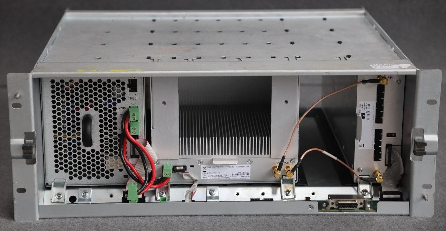
CASTBCHGB
May 12, 2026Base Station Transceiver
Equipment Class
TNB - Licensed Non-Broadcast Station Transmitter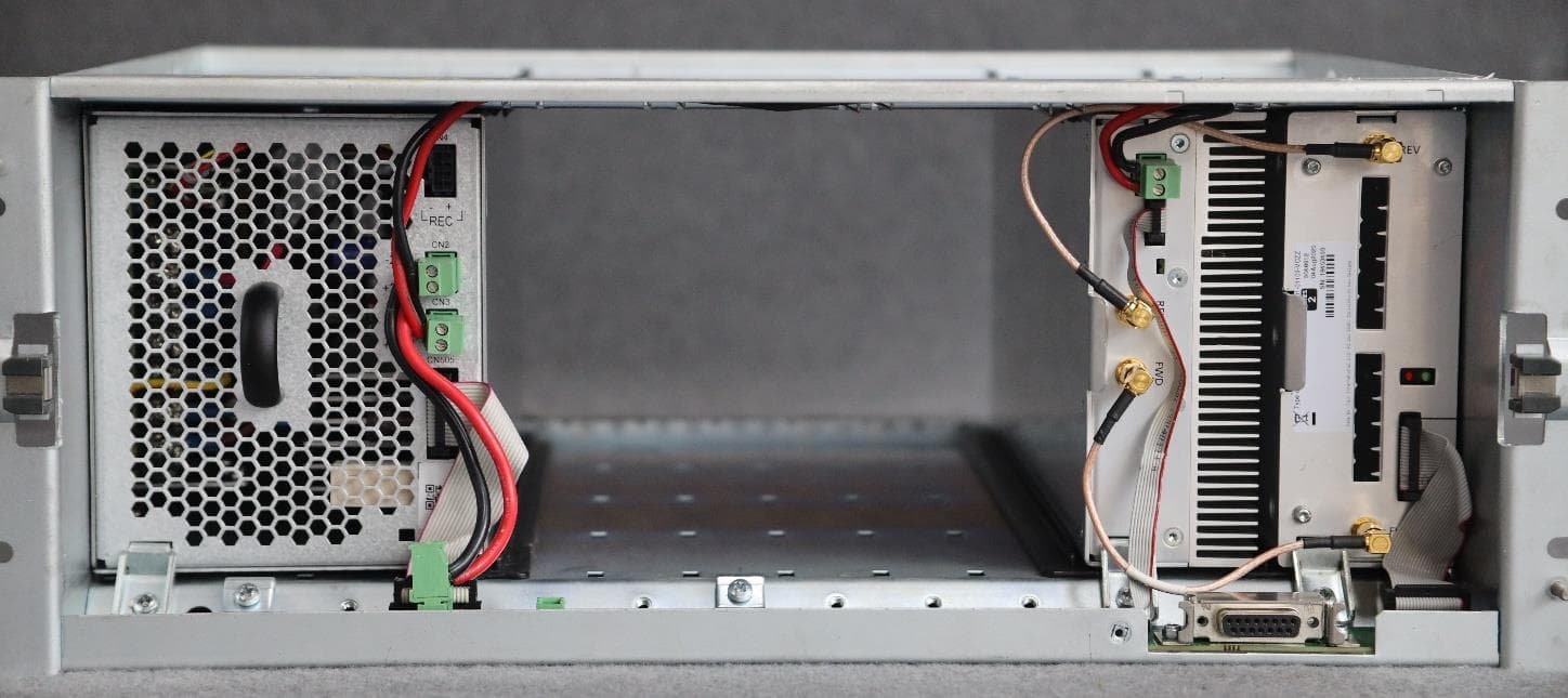
CASTBCHGA
May 12, 2026Base Station Transceiver
Equipment Class
TNB - Licensed Non-Broadcast Station Transmitter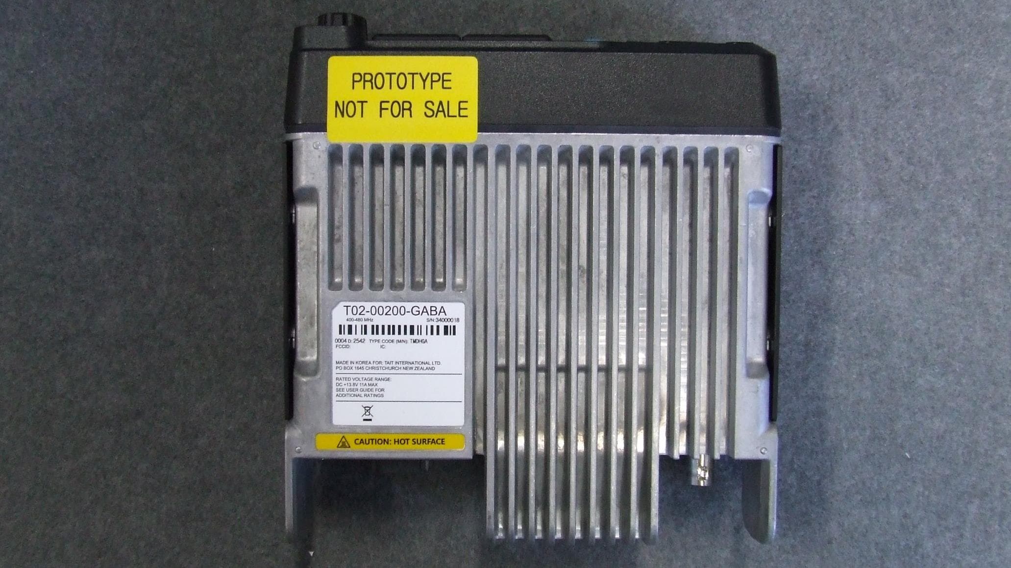
CASTMDHGA
Feb 04, 2026Mobile Transceiver
Equipment Class
TNB - Licensed Non-Broadcast Station Transmitter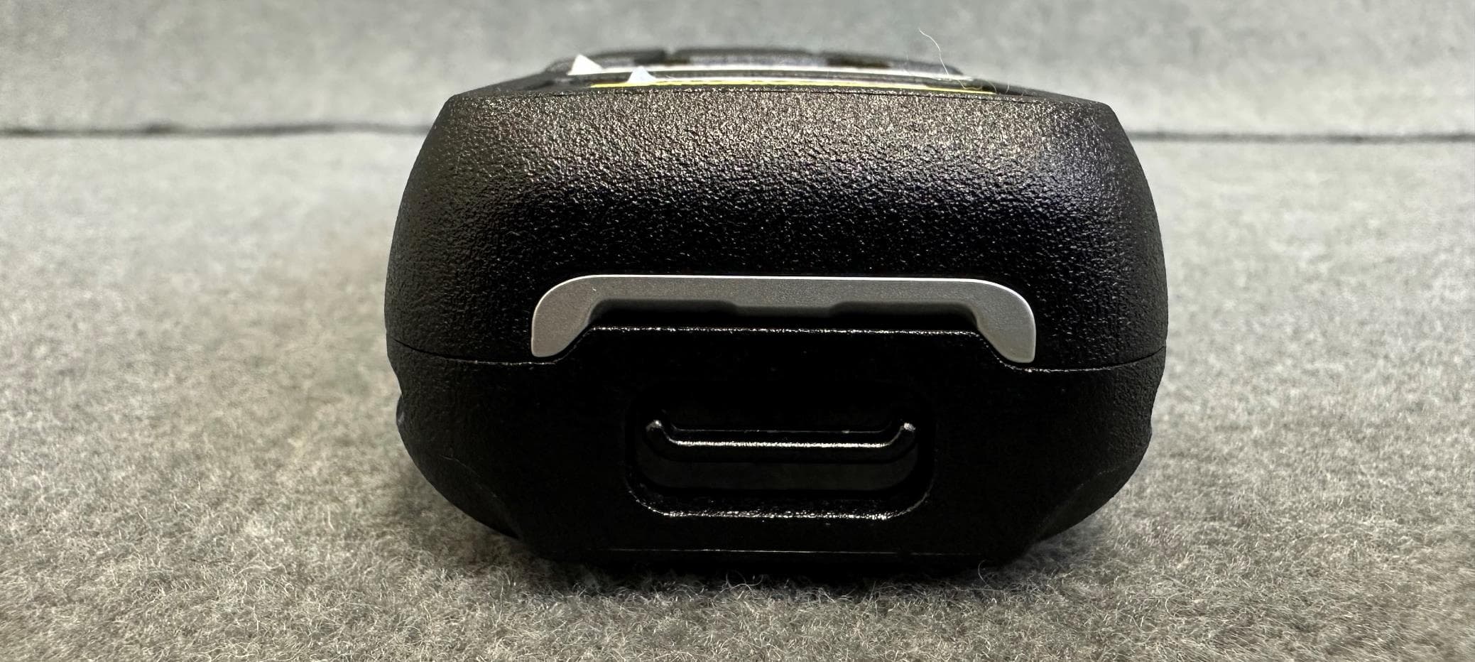
CASTPJHGB
Jan 15, 2026Portable Transceiver
Equipment Class
TNF - Licensed Non-Broadcast Transmitter Held to Face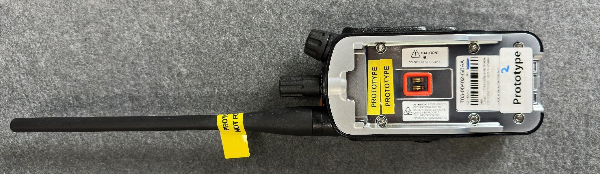
CASTPJHGA
Jan 15, 2026Portable Transceiver
Equipment Class
DSS - Part 15 Spread Spectrum Transmitter