CASTBCHGBBase Station Transceiver
Tait International Limited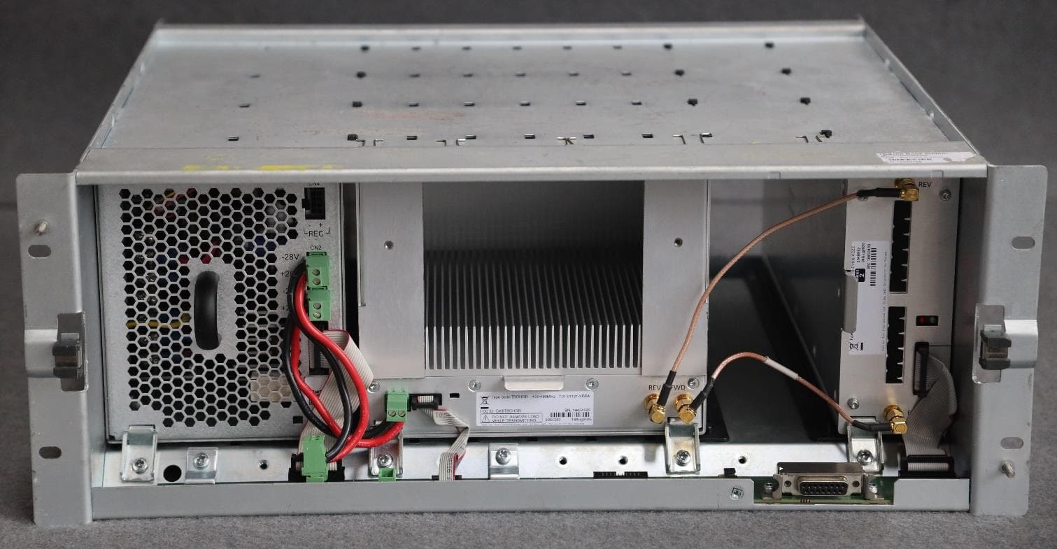
Click to zoom
Application Details
- Equipment Class
- TNB - Licensed Non-Broadcast Station Transmitter
- Date of Grant
- May 12, 2026
- Application Purpose
- Original Equipment
- Equipment Note
- Base Station Transceiver
- Frequency Range
- 406.10000000 - 480.00000000
- Company
- Tait International Limited
- Country
- New Zealand
Documents & Files
Document Text
Text extracted from the exhibit documents filed with the FCC. Open a document above to read the original.
Users Manual
42 General Safety and Regulatory InformationTB9400/TN9275 Installation and Operation © Tait International Limited Draft 2025 2 General Safety and Regulatory Information This chapter provides general information on safety precautions for operating the base station. 2.1 Personal Safety 2.1.1 Unpacking and Moving the Equipment To prevent personal injury and equipment damage, we recommend that two people unpack and move the equipment. CautionA subrack complete with modules can weigh up to 55lb (25kg), or up to 62lb (28kg) complete with packaging. We recommend that you have another person help you unpack and move the equipment. The TBAA03-16 carrying handles will make it easier to move the equipment once it has been unpacked. If necessary, remove the modules from the subrack before moving it (refer to Replacing Modules on page 136). In all cases follow safe lifting practices. 2.1.2 Lethal Voltages Warning The PMU contains voltages that may be lethal. Refer to the ratings label on the rear of the module. The equipment must be installed so that the rear of the PMU is located in a service access area which is accessible only by qualified personnel. The PMU must be connected to the mains supply source by qualified personnel in accordance with local and national regulations. Disconnect the mains IEC connector and wait for five minutes for the internal voltages to self-discharge before dismantling. The AC power on/off switch does not isolate the PMU from the mains. It breaks only the phase circuit, not the neutral. The PMU should be serviced only by qualified technicians. There are no user-replaceable parts inside. If the PMU is damaged and does not function properly, stop the module safely and contact your regional Tait office immediately. TB9400/TN9275 Installation and OperationGeneral Safety and Regulatory Information 43 © Tait International Limited Draft 2025 All servicing should be carried out only when the PMU is powered through a mains isolating transformer of sufficient rating. 2.1.3 AC Power Connection 2.1.4 Explosive Environments Warning Do not operate the equipment near electrical blasting caps or in an explosive atmosphere. Operating the equipment in these environments is a definite safety hazard. 2.1.5 High Temperatures Take care when handling a PMU or PA which has been operating recently. Under extreme operating conditions (+140°F [+60°C] ambient air temperature) or high duty cycles, the external surfaces of the PMU and PA can reach temperatures of up to +176°F (+80°C). 2.1.6 LED Safety (EN60825-1) This equipment contains Class 1 LED Products. English (en)The PMU must be connected to a grounded mains socket-outlet. Norsk (no)Apparatet må tilkoples jordet stikkontakt. Suomi (fi)Laite on liitettävä suojamaadoitus-koskettimilla varustettuun pistorasiaan. Svenska (sv)Apparaten skall anslutas till jordat uttag. 44 General Safety and Regulatory InformationTB9400/TN9275 Installation and Operation © Tait International Limited Draft 2025 2.1.7 Proximity to RF Transmissions / A proximité des émissions RF To comply with the RF Field Limits for Devices Used by the General Public for (Uncontrolled Environment) a , a safe separation distance of at least 22 feet (6.5 meters) from the antenna system should be maintained. This figure is calculated for a typical installation, employing one 100W base station transmitter. Other configurations, including installations at multi-transmitter sites, must be installed so that they comply with the relevant RF exposure standards. a. Reference Standards Health Canadas Safety Code 6: Limits of Human Exposure to Radiofrequency Electromagnetic Energy in the Frequency Range from 3kHz to 300GHz USA Federal Communications Commission OET bulletin 65 (47CFR 1.1310) IEEE C95.1 2005: Standard for Safety Levels with Respect to Human Exposure to Radio Frequency Electromagnetic Fields, 3kHz to 300GHz Pour respecter les limites imposées au champ RF au niveau des équipements utilisés par le grand public (environnement non contrôlé) a , une distance de séparation de sécurité dau moins 6.5 mètres du bloc dantenne devrait être observée. Ce nombre est calculé pour une installation typique, ayant un émetteur de station de base de 100W. Dautres configurations, incluant les installations ayant des sites de plusieurs émetteurs, doivent être installées de façon à se conformer aux normes pertinentes des expositions RF. a. Normes de référence Code de sécurité 6 de Santé Canada: Limites d'exposition humaine à lénergie électromagnétique radioélectrique dans la gamme de fréquences de 3kHz à 300GHz Commission fédérale des communications (FCC) des Etats Unis dAmérique bulletin OET numéro 65 (47CFR 1.1310) IEEE C95.1 2005: Norme pour les niveaux de sécurité compatibles avec l'exposition des personnes aux champs électromagnétiques de radiofréquence 3kHz à 300GHz TB9400/TN9275 Installation and OperationGeneral Safety and Regulatory Information 45 © Tait International Limited Draft 2025 2.2 Equipment Safety 2.2.1 Installation and Servicing Personnel The equipment should be installed and serviced only by qualified personnel. 2.2.2 Preventing Damage to the PA The base station has been designed to operate safely under a wide range of antenna loading conditions. Transmitting into a low VSWR will maximize the power delivered to the antenna. NoticeDo not remove the load from the PA while it is transmitting. Load transients (switching or removing the load) can damage the PA output stage. See Connecting RF on page 89 for recommendations. 2.2.3 ESD Precautions NoticeWhen working on and maintaining base station radio equip- ment, ESD precautions should be taken to avoid electrostatic discharges onto exposed connector pins. For example, wear a ESD wrist strap that is grounded to the equipment chassis. We recommend you purchase an antistatic bench kit from a reputable manufacturer and install and test it according to the manufacturers instructions. Figure 2.1 shows a typical antistatic bench set-up…
Text truncated - open the document above for the full version.
Users Manual
90InstallationTB9400/TN9275 Installation and Operation © Tait International Limited Draft 2025 4.6.6Connecting an External Frequency Reference NoticeAn external reference is required for simulcast operation. For K4 band, the internal frequency reference accuracy is inadequate, and an external reference must be used. An external reference is also required for simulcast and P25 Phase 2. The external reference frequency can be 10 MHz or 12.8 MHz, with an input level of 300 mV pp to 5 V pp . The reciter automatically detects the frequency of the external reference and configures itself accordingly. The stability of this reference should be as shown below. For more details, refer to the P25 and AS-IP Channel Group System Manual (MND-00002-xx). If an external reference is required, enable the “external reference absent” alarm (Configure > Alarms > Control). Use a 50Ω coaxial cable (RG58 or RG223) to connect the external reference to the base station’s external reference frequency input. You can daisy-chain up to eight base stations using BNC goal post adaptors (see Figure 4.13). The maximum overall cable length is 30 m. Terminate the last connection (including single base stations) with a 50Ω load. MulticastP25 Phase 1 P25 Phase 1 P25 Phase 2 B and H bands K4 band All bands Not required 100 parts per billion 100 parts per billion SimulcastP25 Phase 1 P25 Phase 2 All bands10 parts per billion Figure 4.12 Daisy-chaining an external frequency reference input 50Ω termination (also needed for single base stations) maximum of eight base station loads on one frequency reference output maximum overall cable length is 30 m TB9400/TN9275 Installation and OperationInstallation91 © Tait International Limited Draft 2025 Figure 4.13 BNC goal post adaptor (part number 240-06913-00) 4.6.7Connecting a 1 PPS Source A 1 PPS signal is required for simulcast and P25 Phase 2 base stations. Use a 50Ω coaxial cable (RG58 or RG223) to connect the source to the base station’s 1 PPS input. You can daisy-chain up to eight base stations using BNC goal post adaptors (see Figure 4.13). We recommend that the cable length between the first and last load is kept to a minimum. This will reduce any propagation variation between base stations. The maximum overall cable length is 30 m. Terminate the last connection (including single base stations) with a 50Ω resistor, otherwise reflections of the 1PPS pulse may occur. NoticeIf 1PPS is used then 1PPS and NTP must both be derived from the same time base. Normally this will be a GPS disciplined source. Figure 4.14 Daisy-chaining a 1PPS input The longest length of cable must be between the source and the first base station use short lengths of cable between each base station maximum of eight base station loads on one 1 PPS output 50Ω termination (also needed for single base stations) 92InstallationTB9400/TN9275 Installation and Operation © Tait International Limited Draft 2025 4.6.8Ethernet Connection The RJ-45 socket on the reciter’s rear panel provides the 10-BASE-T or 100-BASE-T Ethernet connection to the other devices in the network. Use a Cat-5 cable to connect this socket to the Tait Network via a router or switch. The WebUI allows you to set the Ethernet port speed auto-negotiation to 10/100 Mbit/s or to negotiate a maximum 10 Mbit/s. Tait recommends that you keep the port speed at the factory default setting of 10 Mbit/s. The reciter hardware and firmware are scaled to meet the performance requirements for processing multiple voice streams along with supervisory control and management communications. 10 Mbit/s is ample for these requirements. The 10/100 Mbit/s setting is provided for compatibility reasons, but with a 100 Mbit/s rate and high traffic conditions at the reciter, small windows of internal buffer overflow may occur. These overflows cause packet loss. If you set the port speed to 100 Mbit/s and observe QoS lost packet alarms, then review your Ethernet port speed settings. With the port speed at 10 Mbit/s, it is particularly important to set the voice QoS on the reciter port of your site router or switch to a strict priority queue policy - which is the same policy that you should also be setting for your site link ports. The default QoS settings restrict the voice bandwidth to 1/ 25th of the port speed, which is smaller than the required bandwidth for typical systems at 10 Mbit/s. If necessary, refer to “Ethernet Connector” on page 146 for a list of Ethernet connection pin allocations. TB9400/TN9275 Installation and OperationInstallation93 © Tait International Limited Draft 2025 4.6.9Connecting General Purpose Inputs and Outputs General purpose inputs and outputs are connected via the DB-25 connector on the rear panel of the base station. Analog line operation requires reciter hardware version 1.01 or later. Reciters with hardware version 1.0 can be upgraded to version 1.01 at a Tait service center. Contact your Tait dealer for details. The existing Tx key and Rx gate signals are sufficient for balanced audio interconnection with connecting equipment compatible with 5V TTL level signaling. Tait also offers an isolation adapter that provides E&M isolated signaling (order number TBC101A). It is recommended that E&M isolated signaling be used in the following situations: ■Locally connected equipment that is not 5V TTL signaling compatible ■There is significant distance between connected equipment, and voltage transients could cause equipment damage From V3.40.00, unbalanced audio in and out are supported. Unbalanced Audio In - pin 5 The unbalanced audio input is AC coupled via a 10uF capacitor. Any DC offset that may be present on an audio signal used to modulate the base station transmitter is blocked by this capacitor. Selecting extended bypass mode will DC couple the unbalanced audio input path. Note: a license is required to enable selection of extended bypass mode. Unbalanced Audio Out - pin 3 The unbalanced audio output is DC coupled and has a 2.5V DC offset. For …
Text truncated - open the document above for the full version.
Users Manual
TB9400 Base Station/Repeater TN9275 P25 Analog Gateway Installation and Operation Manual MBC-00001-39 · Issue 39 · Draft 2025 2TB9400/TN9275 Installation and Operation © Tait International Limited Draft 2025 Contact Information Tait Communications Corporate Head Office Tait International Limited P.O. Box 1645 Christchurch New Zealand For the address and telephone number of regional offices, refer to our website: www.taitcommunications.com Copyright and Trademarks All information contained in this document is the property of Tait International Limited. All rights reserved. This document may not, in whole or in part, be copied, photocopied, reproduced, translated, stored, or reduced to any electronic medium or machine- readable form, without prior written permission from Tait International Limited. The word TAIT, TAITNET and the TAIT logo are trademarks of Tait International Limited. All trade names referenced are the service mark, trademark or registered trademark of the respective manufacturers. By using a Tait product you are agreeing to be bound by the terms of the Tait Software Licence Agreement. Please read the Tait Software Licence Agreement carefully before using this Tait product. If you do not agree to the terms of the Tait Software Licence Agreement, do not use the Tait Product. The full agreement is available at www.taitcommunications.com/our-resources/ legal#Software_Licence_Agreement. Disclaimer There are no warranties extended or granted by this document. Tait International Limited accepts no responsibility for damage arising from use of the information contained in the document or of the equipment and software it describes. It is the responsibility of the user to ensure that use of such information, equipment and software complies with the laws, rules and regulations of the applicable jurisdictions. Enquiries and Comments If you have any enquiries regarding this document, or any comments, suggestions and notifications of errors, please contact your regional Tait office. Updates of Manual and Equipment In the interests of improving the performance, reliability or servicing of the equipment, Tait International Limited reserves the right to update the equipment or this document or both without prior notice. Intellectual Property Rights This product may also be made under license under one or more of the following patents: - US7203207, AU2004246135, CA2527142, GB2418107, HK1082608, MY134526, US8306071 - US7339917, AU2004246136, CA2526926, GB2418812, MY134217 - US7499441, AU2005262626, CA2570441, GB2430333, JP4690397, NZ551231, KR100869043, RU2351080, BRP10512052, MXPA06015241 - US 7200129, AU2005226531, CA2558551, CN1930809, GB2429378, JP4351720, BRP10508671, NZ549124, KR848483, RU2321952 Environmental Responsibilities Tait International Limited is an environmentally responsible company which supports waste minimization, material recovery and restrictions in the use of hazardous materials. The European Union’s Waste Electrical and Electronic Equipment (WEEE) Directive requires that this product be disposed of separately from the general waste stream when its service life is over. For more information about how to dispose of your unwanted Tait product, visit the Tait WEEE website at www.taitcommunications.com/our- resources/compliance#WEEE. Please be environmentally responsible and dispose through the original supplier, or contact Tait International Limited. Tait will comply with environmental requirements in other markets as they are introduced. Imported into the EU by: Tait Communications GmbH Strozzigasse 10 / 14 Vienna 1080 Austria Imported into the UK by: Tait Europe Limited Unit A, Buckingham Business Park, Anderson Road Swavesey Cambridge, CB24 4UQ United Kingdom TB9400/TN9275 Installation and Operation3 © Tait International Limited Draft 2025 Contents Preface . . . . . . . . . . . . . . . . . . . . . . . . . . . . . . . . . . . . . . . . . . . . . . . . . . . . . . . . . . . . . . . . . . . . . 7 Scope of Manual. . . . . . . . . . . . . . . . . . . . . . . . . . . . . . . . . . . . . . . . . . . . . . . . . . . . . . . . 7 Alerts . . . . . . . . . . . . . . . . . . . . . . . . . . . . . . . . . . . . . . . . . . . . . . . . . . . . . . . . . . . . . . . . 7 Associated Documentation. . . . . . . . . . . . . . . . . . . . . . . . . . . . . . . . . . . . . . . . . . . . . . . . 8 Publication Record . . . . . . . . . . . . . . . . . . . . . . . . . . . . . . . . . . . . . . . . . . . . . . . . . . . . . . 8 1Description . . . . . . . . . . . . . . . . . . . . . . . . . . . . . . . . . . . . . . . . . . . . . . . . . . . . . . . . . . . . . .11 1.1 Series 2 and Series 1 Reciters . . . . . . . . . . . . . . . . . . . . . . . . . . . . . . . . . . . . . . . . 12 1.1.1 Identifying a Series 2 Reciter . . . . . . . . . . . . . . . . . . . . . . . . . . . . . . . . 12 1.1.2 New Reciters and Repairs . . . . . . . . . . . . . . . . . . . . . . . . . . . . . . . . . . . 13 1.1.3 Firmware Information . . . . . . . . . . . . . . . . . . . . . . . . . . . . . . . . . . . . . . 13 1.1.4 Series 1 and Series 2 Feature Compatibility . . . . . . . . . . . . . . . . . . . . . 14 1.2 Firmware Applications . . . . . . . . . . . . . . . . . . . . . . . . . . . . . . . . . . . . . . . . . . . . . . 14 1.2.1 Base Station Features. . . . . . . . . . . . . . . . . . . . . . . . . . . . . . . . . . . . . . . 14 1.3 Firmware Application Details . . . . . . . . . . . . . . . . . . . . . . . . . . . . . . . . . . . . . . . . 16 1.3.1 P25/AS-IP . . . . . . . . . . . . . . . . . . . . . . . . . . . . . . . . . . . . . . . . . . . . . . . 16 1.3.2 P25 Gateway Key Management . . . . . . . . . . . . . . . . . . . . . . . . . . . . . . 17 1.3.3 DMR/MPT. . . . . . . . . . . . . . . . . . . . . . . . . . . . . . . . . . . . . . . . . . . . . . . 18 1.4 Modules . . . . . . . . . . . . . . . . . . . . . . . . . . . . . . . . . . . . . . . . . . . . . . . . . . . . . . . . . 19 1.5 Mechanical Assembly . . . . . . .…
Text truncated - open the document above for the full version.
Internal Photos
Tait International Ltd 245 Wooldridge Rd Christchurch 8051 New Zealand +64 3 358 3399, www.taitradio.com Page 1 of 16 Tait International Ltd Internal Photographs Exhibit (Dec 2025) Product: TB9300/TB9400 Type code: TBCHGB FCC ID: CASTBCHGB IC: 737A-TBCHGB Tait International Ltd 245 Wooldridge Rd Christchurch 8051 New Zealand +64 3 358 3399, www.taitradio.com Page 2 of 16 Photograph 01: Base station – Front view – Open Tait International Ltd 245 Wooldridge Rd Christchurch 8051 New Zealand +64 3 358 3399, www.taitradio.com Page 3 of 16 Photograph 02: Reciter – Front view Photograph 03: Reciter – Rear view Tait International Ltd 245 Wooldridge Rd Christchurch 8051 New Zealand +64 3 358 3399, www.taitradio.com Page 4 of 16 Photograph 04: Reciter – Top view Photograph 05: Reciter Control board PCB – Top Tait International Ltd 245 Wooldridge Rd Christchurch 8051 New Zealand +64 3 358 3399, www.taitradio.com Page 5 of 16 Photograph 06: Reciter Control board PCB – Bottom Photograph 07: Reciter Control board PCB – Top (without cans) Tait International Ltd 245 Wooldridge Rd Christchurch 8051 New Zealand +64 3 358 3399, www.taitradio.com Page 6 of 16 Photograph 8: Reciter Rx PCB – Top Tait International Ltd 245 Wooldridge Rd Christchurch 8051 New Zealand +64 3 358 3399, www.taitradio.com Page 7 of 16 Photograph 9: Reciter Rx PCB – Top (without cans) Photograph 10: Reciter Rx PCB - Bottom Tait International Ltd 245 Wooldridge Rd Christchurch 8051 New Zealand +64 3 358 3399, www.taitradio.com Page 8 of 16 Photograph 11: Reciter TxF PCB - Top Photograph 12: Reciter TxF PCB – Top (without cans) Tait International Ltd 245 Wooldridge Rd Christchurch 8051 New Zealand +64 3 358 3399, www.taitradio.com Page 9 of 16 Photograph 13: Reciter TxF PCB – Bottom Tait International Ltd 245 Wooldridge Rd Christchurch 8051 New Zealand +64 3 358 3399, www.taitradio.com Page 10 of 16 Photograph 14: Reciter Tx Reverse PCB – Top Photograph 15: Reciter Tx Reverse PCB – Top (without cans) Tait International Ltd 245 Wooldridge Rd Christchurch 8051 New Zealand +64 3 358 3399, www.taitradio.com Page 11 of 16 Photograph 16: Reciter Tx Reverse PCB – Bottom Tait International Ltd 245 Wooldridge Rd Christchurch 8051 New Zealand +64 3 358 3399, www.taitradio.com Page 12 of 16 Photograph 17: PA – Front view Tait International Ltd 245 Wooldridge Rd Christchurch 8051 New Zealand +64 3 358 3399, www.taitradio.com Page 13 of 16 Photograph 18: PA – Rear view Tait International Ltd 245 Wooldridge Rd Christchurch 8051 New Zealand +64 3 358 3399, www.taitradio.com Page 14 of 16 Photograph 19: PA PCB --Top Tait International Ltd 245 Wooldridge Rd Christchurch 8051 New Zealand +64 3 358 3399, www.taitradio.com Page 15 of 16 Photograph 20: PA PCB –Top (Without Cans) Tait International Ltd 245 Wooldridge Rd Christchurch 8051 New Zealand +64 3 358 3399, www.taitradio.com Page 16 of 16 Photograph 21: PA PCB –Bottom
Test Report
TELTEST Laboratories Tait International Ltd Report Number 4439 FCC ID: CASTBCHGB Page 49 of 127 Report Revision: 1 IC : 737A-TBCHGB Issue Date: 08 August 2025 Transmitter Spectrum Masks FFSK 1200 bps SPECIFICATION: FCC CFR 2.1049 (c) RSS-119 5.5 Tx FREQUENCY: 460.025 MHz 100 W 12.5 kHz Channel Spacing Tx FREQUENCY: 460.025 MHz 10 W 12.5 kHz Channel Spacing TELTEST Laboratories Tait International Ltd Report Number 4439 FCC ID: CASTBCHGB Page 50 of 127 Report Revision: 1 IC : 737A-TBCHGB Issue Date: 08 August 2025 Transmitter Spectrum Masks FFSK 1200 bps SPECIFICATION: FCC CFR 2.1049 (c) RSS-119 5.5 Tx FREQUENCY: 469.975 MHz 100 W 12.5 kHz Channel Spacing Tx FREQUENCY: 469.975 MHz 10 W 12.5 kHz Channel Spacing TELTEST Laboratories Tait International Ltd Report Number 4439 FCC ID: CASTBCHGB Page 51 of 127 Report Revision: 1 IC : 737A-TBCHGB Issue Date: 08 August 2025 Transmitter Spectrum Masks P25 Phase 1 C4FM SPECIFICATION: FCC CFR 2.1049 (c) RSS-119 5.5 Tx FREQUENCY: 406.125 MHz 100 W 12.5 kHz Channel Spacing Tx FREQUENCY: 406.125 MHz 10 W 12.5 kHz Channel Spacing TELTEST Laboratories Tait International Ltd Report Number 4439 FCC ID: CASTBCHGB Page 52 of 127 Report Revision: 1 IC : 737A-TBCHGB Issue Date: 08 August 2025 Transmitter Spectrum Masks P25 Phase 1 C4FM SPECIFICATION: FCC CFR 2.1049 (c) RSS-119 5.5 Tx FREQUENCY: 418.025 MHz 100 W 12.5 kHz Channel Spacing Tx FREQUENCY: 418.025 MHz 10 W 12.5 kHz Channel Spacing TELTEST Laboratories Tait International Ltd Report Number 4439 FCC ID: CASTBCHGB Page 53 of 127 Report Revision: 1 IC : 737A-TBCHGB Issue Date: 08 August 2025 Transmitter Spectrum Masks DMR SPECIFICATION: FCC CFR 2.1049 (c) RSS-119 5.5 Tx FREQUENCY: 429.975 MHz 100 W 12.5 kHz Channel Spacing Tx FREQUENCY: 429.975 MHz 10 W 12.5 kHz Channel Spacing TELTEST Laboratories Tait International Ltd Report Number 4439 FCC ID: CASTBCHGB Page 54 of 127 Report Revision: 1 IC : 737A-TBCHGB Issue Date: 08 August 2025 Transmitter Spectrum Masks DMR SPECIFICATION: FCC CFR 2.1049 (c) RSS-119 5.5 Tx FREQUENCY: 450.025 MHz 100 W 12.5 kHz Channel Spacing Tx FREQUENCY: 450.025 MHz 10 W 12.5 kHz Channel Spacing TELTEST Laboratories Tait International Ltd Report Number 4439 FCC ID: CASTBCHGB Page 55 of 127 Report Revision: 1 IC : 737A-TBCHGB Issue Date: 08 August 2025 Transmitter Spectrum Masks DMR SPECIFICATION: FCC CFR 2.1049 (c) RSS-119 5.5 Tx FREQUENCY: 460.025 MHz 100 W 12.5 kHz Channel Spacing Tx FREQUENCY: 460.025 MHz 10 W 12.5 kHz Channel Spacing TELTEST Laboratories Tait International Ltd Report Number 4439 FCC ID: CASTBCHGB Page 56 of 127 Report Revision: 1 IC : 737A-TBCHGB Issue Date: 08 August 2025 Transmitter Spectrum Masks DMR SPECIFICATION: FCC CFR 2.1049 (c) RSS-119 5.5 Tx FREQUENCY: 469.975 MHz 100 W 12.5 kHz Channel Spacing Tx FREQUENCY: 469.975 MHz 10 W 12.5 kHz Channel Spacing TELTEST Laboratories Tait International Ltd Report Number 4439 FCC ID: CASTBCHGB Page 57 of 127 Report Revision: 1 IC : 737A-TBCHGB Issue Date: 08 August 2025 Transmitter Spectrum Masks P25 PHASE 1 LSM SPECIFICATION: FCC CFR 2.1049 (c) RSS-119 5.5 Tx FREQUENCY: 406.125 MHz 100 W 12.5 kHz Channel Spacing Tx FREQUENCY: 406.125 MHz 10 W 12.5 kHz Channel Spacing TELTEST Laboratories Tait International Ltd Report Number 4439 FCC ID: CASTBCHGB Page 58 of 127 Report Revision: 1 IC : 737A-TBCHGB Issue Date: 08 August 2025 Transmitter Spectrum Masks P25 PHASE 1 LSM SPECIFICATION: FCC CFR 2.1049 (c) RSS-119 5.5 Tx FREQUENCY: 418.025 MHz 100 W 12.5 kHz Channel Spacing Tx FREQUENCY: 418.025 MHz 10 W 12.5 kHz Channel Spacing TELTEST Laboratories Tait International Ltd Report Number 4439 FCC ID: CASTBCHGB Page 59 of 127 Report Revision: 1 IC : 737A-TBCHGB Issue Date: 08 August 2025 Transmitter Spectrum Masks P25 PHASE 1 LSM SPECIFICATION: FCC CFR 2.1049 (c) RSS-119 5.5 Tx FREQUENCY: 429.975 MHz 100 W 12.5 kHz Channel Spacing Tx FREQUENCY: 429.975 MHz 10 W 12.5 kHz Channel Spacing TELTEST Laboratories Tait International Ltd Report Number 4439 FCC ID: CASTBCHGB Page 60 of 127 Report Revision: 1 IC : 737A-TBCHGB Issue Date: 08 August 2025 Transmitter Spectrum Masks P25 PHASE 1 LSM SPECIFICATION: FCC CFR 2.1049 (c) RSS-119 5.5 Tx FREQUENCY: 450.025 MHz 100 W 12.5 kHz Channel Spacing Tx FREQUENCY: 450.025 MHz 10 W 12.5 kHz Channel Spacing TELTEST Laboratories Tait International Ltd Report Number 4439 FCC ID: CASTBCHGB Page 61 of 127 Report Revision: 1 IC : 737A-TBCHGB Issue Date: 08 August 2025 Transmitter Spectrum Masks P25 PHASE 1 LSM SPECIFICATION: FCC CFR 2.1049 (c) RSS-119 5.5 Tx FREQUENCY: 460.025 MHz 100 W 12.5 kHz Channel Spacing Tx FREQUENCY: 460.025 MHz 10 W 12.5 kHz Channel Spacing TELTEST Laboratories Tait International Ltd Report Number 4439 FCC ID: CASTBCHGB Page 62 of 127 Report Revision: 1 IC : 737A-TBCHGB Issue Date: 08 August 2025 Transmitter Spectrum Masks P25 PHASE 1 LSM SPECIFICATION: FCC CFR 2.1049 (c) RSS-119 5.5 Tx FREQUENCY: 469.975 MHz 100 W 12.5 kHz Channel Spacing Tx FREQUENCY: 469.975 MHz 10 W 12.5 kHz Channel Spacing TELTEST Laboratories Tait International Ltd Report Number 4439 FCC ID: CASTBCHGB Page 63 of 127 Report Revision: 1 IC : 737A-TBCHGB Issue Date: 08 August 2025 Transmitter Spectrum Masks P25 PHASE 2 H-DQPSK SPECIFICATION: FCC CFR 2.1049 (c) RSS-119 5.5 Tx FREQUENCY: 406.125 MHz 100 W 12.5 kHz Channel Spacing Tx FREQUENCY: 406.125 MHz 10 W 12.5 kHz Channel Spacing TELTEST Laboratories Tait International Ltd Report Number 4439 FCC ID: CASTBCHGB Page 64 of 127 Report Revision: 1 IC : 737A-TBCHGB Issue Date: 08 August 2025 Transmitter Spectrum Masks P25 PHASE 2 H-DQPSK SPECIFICATION: FCC CFR 2.1049 (c) RSS-119 5.5 Tx FREQUENCY: 418.025 MHz 100 W 12.5 kHz Channel Spacing Tx FREQUENCY: 418.025 MHz 10 W 12.5 kHz Channel Spacing TELTEST Laboratories Tait International Ltd Report Number 4439 FCC ID: CASTBCHGB Page 65 of 127 Report Revision: 1 IC : 737A-TBCHGB Issue Date: 08 August 2025 Transmitter Spectrum Masks P25 PHASE 2 H-DQPSK SPECIFICATION: FCC CFR 2.1049 (c) RSS-119 5.5 Tx FREQUENCY: …
Text truncated - open the document above for the full version.
Test Report
TELTEST Laboratories Tait International Ltd Report Number 4439 FCC ID: CASTBCHGB Page 43 of 127 Report Revision: 1 IC : 737A-TBCHGB Issue Date: 08 August 2025 Transmitter Spectrum Masks ANALOGUE VOICE SPECIFICATION: FCC CFR 2.1049 (c) RSS-119 5.5 Tx FREQUENCY: 460.025 MHz 100 W 25.0 kHz Channel Spacing Tx FREQUENCY: 460.025 MHz 10 W 25.0 kHz Channel Spacing TELTEST Laboratories Tait International Ltd Report Number 4439 FCC ID: CASTBCHGB Page 44 of 127 Report Revision: 1 IC : 737A-TBCHGB Issue Date: 08 August 2025 Transmitter Spectrum Masks ANALOGUE VOICE SPECIFICATION: FCC CFR 2.1049 (c) RSS-119 5.5 Tx FREQUENCY: 469.975 MHz 100 W 25.0 kHz Channel Spacing Tx FREQUENCY: 469.975 MHz 10 W 25.0 kHz Channel Spacing TELTEST Laboratories Tait International Ltd Report Number 4439 FCC ID: CASTBCHGB Page 45 of 127 Report Revision: 1 IC : 737A-TBCHGB Issue Date: 08 August 2025 Transmitter Spectrum Masks FFSK 1200 bps SPECIFICATION: FCC CFR 2.1049 (c) RSS-119 5.5 Tx FREQUENCY: 406.125 MHz 100 W 12.5 kHz Channel Spacing Tx FREQUENCY: 406.125 MHz 10 W 12.5 kHz Channel Spacing TELTEST Laboratories Tait International Ltd Report Number 4439 FCC ID: CASTBCHGB Page 46 of 127 Report Revision: 1 IC : 737A-TBCHGB Issue Date: 08 August 2025 Transmitter Spectrum Masks FFSK 1200 bps SPECIFICATION: FCC CFR 2.1049 (c) RSS-119 5.5 Tx FREQUENCY: 418.025 MHz 100 W 12.5 kHz Channel Spacing Tx FREQUENCY: 418.025 MHz 10 W 12.5 kHz Channel Spacing TELTEST Laboratories Tait International Ltd Report Number 4439 FCC ID: CASTBCHGB Page 47 of 127 Report Revision: 1 IC : 737A-TBCHGB Issue Date: 08 August 2025 Transmitter Spectrum Masks FFSK 1200 bps SPECIFICATION: FCC CFR 2.1049 (c) RSS-119 5.5 Tx FREQUENCY: 429.975 MHz 100 W 12.5 kHz Channel Spacing Tx FREQUENCY: 429.975 MHz 10 W 12.5 kHz Channel Spacing TELTEST Laboratories Tait International Ltd Report Number 4439 FCC ID: CASTBCHGB Page 48 of 127 Report Revision: 1 IC : 737A-TBCHGB Issue Date: 08 August 2025 Transmitter Spectrum Masks FFSK 1200 bps SPECIFICATION: FCC CFR 2.1049 (c) RSS-119 5.5 Tx FREQUENCY: 450.025 MHz 100 W 12.5 kHz Channel Spacing Tx FREQUENCY: 450.025 MHz 10 W 12.5 kHz Channel Spacing
Test Report
TELTEST Laboratories Tait International Ltd Report Number 4439 FCC ID: CASTBCHGB Page 24 of 127 Report Revision: 1 IC : 737A-TBCHGB Issue Date: 08 August 2025 TRANSMITTER OCCUPIED (99%) BANDWIDTH SPECIFICATION: FCC 47 CFR 2.1046 RSS-119 5.5 GUIDE: ANSI C63.26 5.4.4 MEASUREMENT PROCEDURE: 1. Refer Annex A for Equipment Set up. 2. For analogue measurements: The EUT was modulated by a 2500 Hz tone at an input level 16 dB above a level that produced 50% deviation. The input level was established at the frequency of maximum response of the audio modulating circuit. For Data measurements: The EUT was modulated with an internally generated pseudo random bit sequence at the appropriate Baud rates. 3. The Occupied Bandwidth was measured on the Spectrum Analyser, with bandwidth settings as follows. Resolution Bandwidth = 100 Hz, Video Bandwidth = 300 Hz MEASUREMENT RESULTS: Bandwidths (kHz) Channel Frequency (MHz) Channel Spacing (kH…
Text truncated - open the document above for the full version.
Contact Information
Applicant
Linda White(Standards and Regulatory Manager)
[email protected]Fax: n
Technical Contact
Tait North AmericaMark Reeves
1315 W Sam Houston Parkway N, Suite 140 · Houston, 77043 · United States
Test Firm
Elite Electronic Engineering Inc.Kevin Halpin
[email protected]Fax: 630-495-9785
Technical Specifications
| # | Rule Parts | Frequency Range | Power Output | Emission | Tolerance |
|---|---|---|---|---|---|
| 1 | 22,9 | 406.1 MHz - 480 MHz | 100 W | 11K0F3E | 0.5ppm |
| 2 | 22,9 | 406.1 MHz - 480 MHz | 100 W | 16K0F3E | 0.5ppm |
| 3 | 22,9 | 406.1 MHz - 480 MHz | 100 W | 7K60F2D | 0.5ppm |
| 4 | 22,9 | 406.1 MHz - 480 MHz | 100 W | 8K10F1E | 0.5ppm |
| 5 | 22,9 | 406.1 MHz - 480 MHz | 100 W | 8K10F1D | 0.5ppm |
| 6 | 22,9 | 406.1 MHz - 480 MHz | 100 W | 8K70D1W | 0.5ppm |
| 7 | 22,9 | 406.1 MHz - 480 MHz | 100 W | 8K70D7W | 0.5ppm |
| 8 | 22,9 | 406.1 MHz - 480 MHz | 100 W | 9K80D7W | 0.5ppm |
| 9 | 22,9 | 406.1 MHz - 480 MHz | 100 W | 8K00FXW | 0.5ppm |
| 1 | 22,9 | 406.1 MHz - 480 MHz | 100 W | 8K00FXD | 0.5ppm |
Other Applications from Tait International Limited
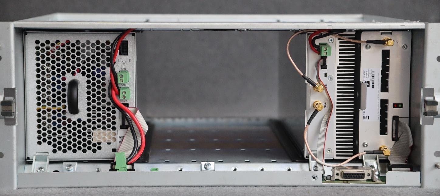
CASTBCHGA
May 12, 2026Base Station Transceiver
Equipment Class
TNB - Licensed Non-Broadcast Station Transmitter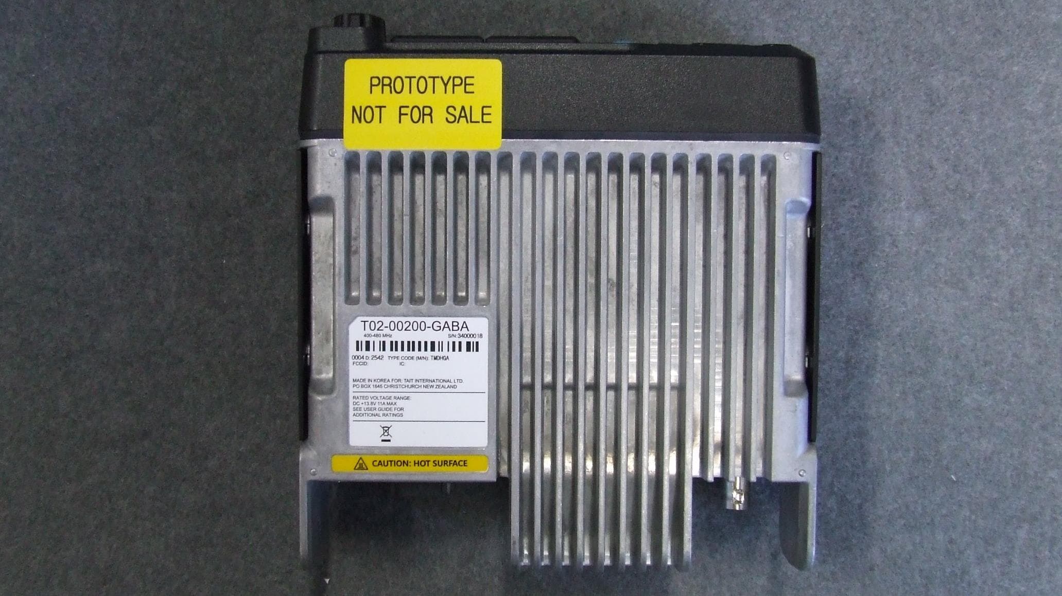
CASTMDHGA
Feb 04, 2026Mobile Transceiver
Equipment Class
TNB - Licensed Non-Broadcast Station Transmitter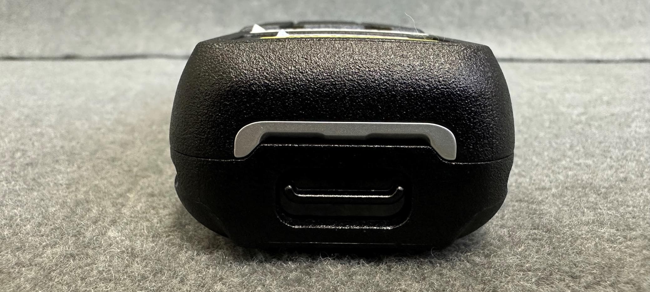
CASTPJHGB
Jan 15, 2026Portable Transceiver
Equipment Class
TNF - Licensed Non-Broadcast Transmitter Held to Face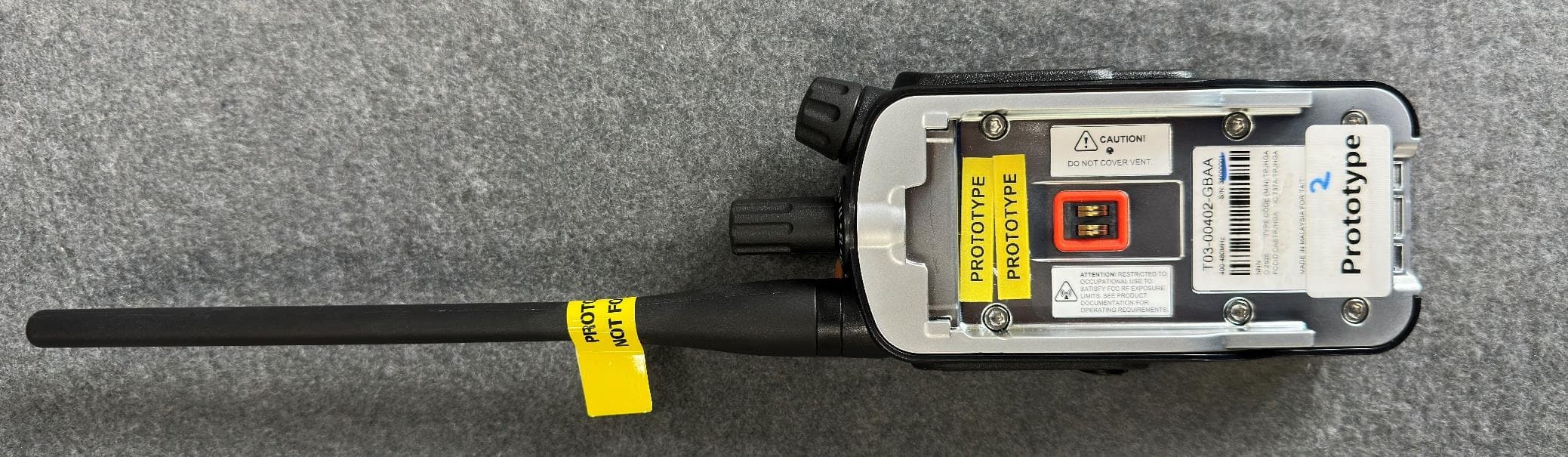
CASTPJHGA
Jan 15, 2026Portable Transceiver
Equipment Class
DSS - Part 15 Spread Spectrum Transmitter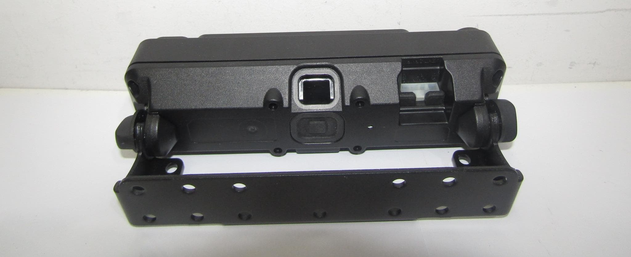
CASTAHP2A
Dec 10, 2025Mobile Accessory
Equipment Class
DTS - Digital Transmission System