CASTBAL0Base Station Transceiver
Tait International Limited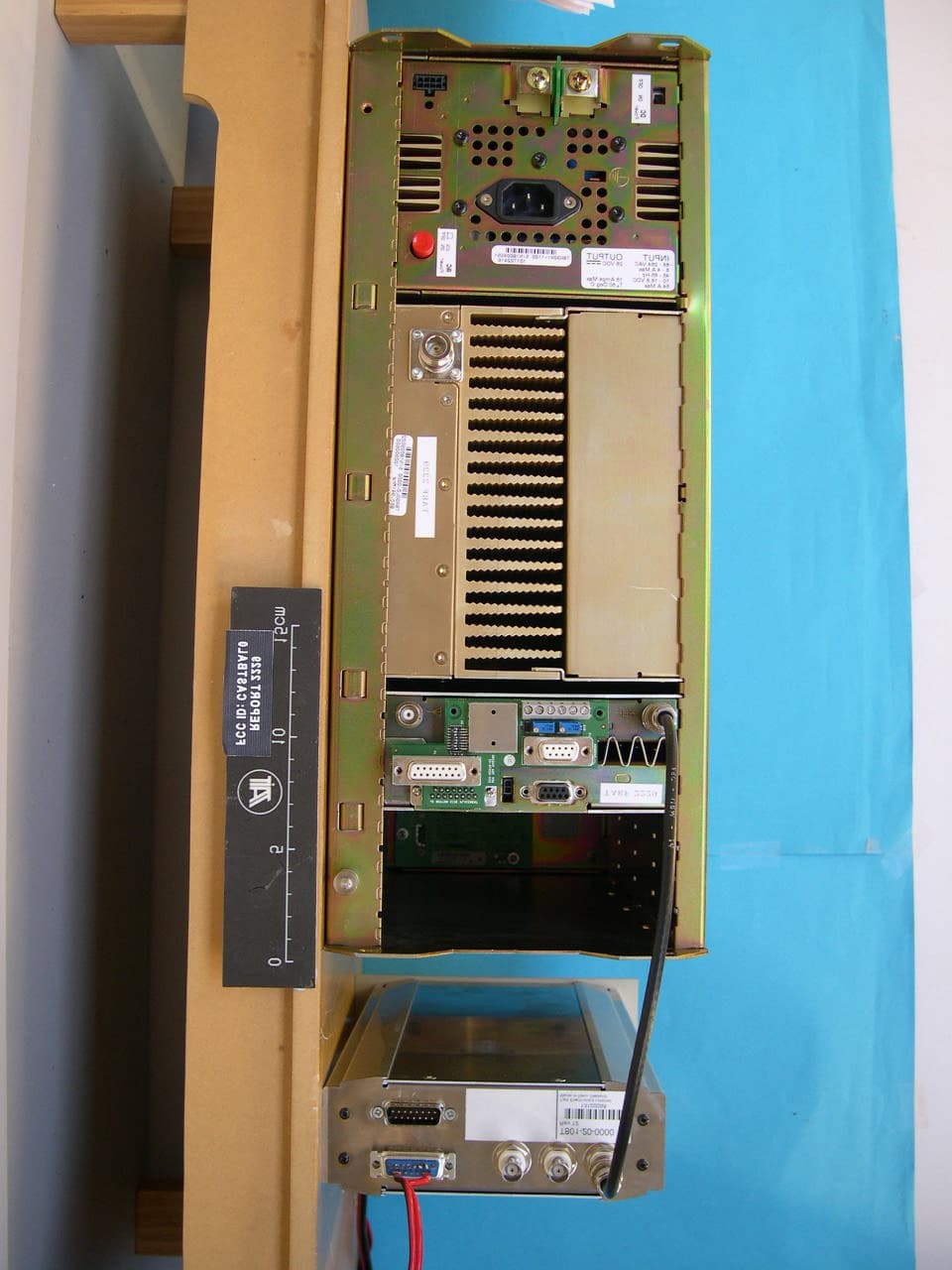
Click to zoom
Application Details
- Equipment Class
- TNB - Licensed Non-Broadcast Station Transmitter
- Date of Grant
- Jul 10, 2005
- Application Purpose
- Original Equipment
- Date of Application
- Jul 10, 2005
- Equipment Note
- Base Station Transceiver
- Frequency Range
- 927.00000000 - 941.00000000
- Company
- Tait International Limited
- Country
- New Zealand
Documents & Files
Document Text
Text extracted from the exhibit documents filed with the FCC. Open a document above to read the original.
Users Manual
Calibration Kit User’s Manual MBA-00011-05 March 2005 TB8100 base station TB8100 Calibration Kit User’s ManualContents i Contents Preface ..............................................................................................................iii Enquiries and Comments ..................................................................iii Updates of Manual and Equipment ...................................................iii Copyright .........................................................................................iii Disclaimer ........................................................................................iii Typographical Conventions ..............................................................iii Associated Documentation ...............................................................iii Publication Record ..........................................................................iv Basic Tasks .........................................................................................................1 Using the TB8100 Calibration Kit ..........................................................1 About the Toolbar ............................................................................2 About the Status Bar ..........................................................................2 Equipment Required ..............................................................................3 Calibration Overview .............................................................................3 Field Calibration ................................................................................4 Service Center Calibration .................................................................4 Selecting the Communications Port ........................................................5 Connecting to a Reciter Outside the Subrack .........................................5 Connecting to a Reciter via the Control Panel .......................................7 Disconnecting from the Base Station/Reciter .........................................7 Troubleshooting .....................................................................................8 Adjusting the Frequency Setup ........................................................................9 Adjusting the Receiver Lock Band .........................................................9 Tuning the Receiver Front End ........................................................... 10 Tuning a K-Band, H-Band, or L-Band Receiver Front End ............ 11 Tuning a VHF Receiver Front End ................................................. 12 Adjusting the Exciter Lock Band .......................................................... 13 Calibrating the Reciter ....................................................................................14 Calibrating the Exciter .......................................................................... 14 Automatically Tune the Frequency Control Loop (FCL) ................. 14 Calibrating the FCL ......................................................................... 14 Calibrating the VCO ....................................................................... 16 Calibrating the RSSI ............................................................................. 17 Audio Calibration ................................................................................. 18 Calibrating the Balanced Lines ......................................................... 18 Calibrating the Unbalanced Lines .................................................... 19 Carrier Frequency Offset Adjustment (Older Reciters) .................................................................................... 21 Carrier Frequency Offset Adjustment (Newer Reciters) .................................................................................. 22 Calibrating the Power Amplifier .................................................................... 24 ii Contents © Tait Electronics Limited 2005 Calibrating the PA Bias ........................................................................ 24 Calibrating the Forward and Reverse Detector Bias Voltages ............... 25 Calibrating the PA Power .................................................................... 25 Troubleshooting Tips ..................................................................... 26 Calibrating the Supply Voltage ............................................................. 27 Calibrating the Power Management Unit .................................................... 28 Calibrating the PMU Output Voltage .................................................. 28 Index .................................................................................. 29 TB8100 Calibration Kit User’s Manual Preface iii Preface Welcome to the TB8100 Calibration Kit User’s Manual. This manual provides you with information about the Tait TB8100 Calibration Kit in PDF format. You can view it online or print it if you want a paper copy. It describes how to use Version 02.05 of the Calibration Kit. Enquiries and Comments Any enquiries regarding this manual as well as any comments, suggestions and notifications of errors should be sent to [email protected], or addressed to the Support Group Manager, Tait Electronics Limited, PO Box 1645 Christchurch, New Zealand. Updates of Manual and Equipment In the interests of improving the performance, reliability or servicing of the equipment, Tait Electronics Limited reserves the right to update the equipment or this manual or both without prior notice. Copyright All information contained in this manual is the property of Tait Electronics Limited. All rights are reserved. This manual may not, in whole or in part, be copied, photocopied, reproduced, translated, stored, or reduced to any electronic medium or machine-readable form, without prior written permission from Tait Electronics Limited. All trade names referenced are the service mark, trademark or registered trad…
Text truncated - open the document above for the full version.
Users Manual
TB8100 Installation and Operation ManualConnection99 © Tait Electronics Limited March 2005 7Connection Once the TB8100 BSS hardware is installed, you need to connect the individual modules to each other, and to any ancillary equipment required in your system. This chapter provides information on all the inputs and outputs available on the TB8100 BSS. 7.1Overview of Inputs and Outputs This section identifies the main input and output connections for the TB8100 BSS. ■Figure 7.1 on page 100 identifies the connections at the front of a dual base station, and Figure 7.4 on page 103 identifies those at the rear. ■Figure 7.2 on page 101 identifies the connections at the front of a dual 12 V PA base station, and Figure 7.5 on page 104 identifies those at the rear. ■Figure 7.3 on page 102 identifies the connections at the front of a single 100 W base station. ■Figure 7.6 on page 104, and Figure 7.7 and Figure 7.8 on page 105 identify the connections on the standard, dual base station, and Power Save control panels. Refer to the following sections in this chapter for more details on these connections. 100ConnectionTB8100 Installation and Operation Manual © Tait Electronics Limited March 2005 ImportantIn base station systems which use a PMU, the PMU must be connected to the system control bus at all times. The I 2 C current source is located in the PMU, and if the PMU is disconnected, the state of much of the bus will be unde- fined. This may cause corrupted data to be present on the bus when the reciter reads the states of the switches on the control panel. This in turn may result in random actuations of microphone PTT, carrier, or speaker key, causing the BSS to transmit or the speaker to be actuated incorrectly. Figure 7.1Dual 5W or 50W base station inputs and outputs - front view b 28VDC high current output for PA f 28VDC high current input cable from PMU c 28 VDC low current output for reciter g RF output to PA d system control bus h 28VDC low current input from PMU e RF input from reciter i DC output (for optional reciter fan only) bcde ghfgh ddidiefd PA 1PA 2reciter 2PMU reciter 1 TB8100 Installation and Operation ManualConnection101 © Tait Electronics Limited March 2005 Figure 7.2Dual 5W or 50W 12V PA base station inputs and outputs - front view b 12VDC output for reciter e 12VDC input from PA c RF input from reciter f DC output (for optional reciter fan only) d RF output to PA g system control bus cdeb gfg PA 2 reciter 1 ed f g reciter 2 b gc PA 1 102ConnectionTB8100 Installation and Operation Manual © Tait Electronics Limited March 2005 Figure 7.3Single 100W base station inputs and outputs - front view b 28VDC high current output for PA f system control bus c 28 VDC low current output for reciter g DC output (for optional reciter fan only) d RF output to PA h 28VDC high current input cable from PMU e 28VDC low current input from PMU i RF input from reciter bcde hfgfi PAre ci te r PMU TB8100 Installation and Operation ManualConnection103 © Tait Electronics Limited March 2005 Figure 7.4Single 5W or 50W base station inputs and outputs - rear view b system interface connector g auxiliary DC output c external reference frequency input h AC mains input d RF output (to antenna) i RF input (from antenna) e – VDC input j auxiliary DC input for system interface a f + VDC input 1) subrack ground connector a. Older system interface boards use the 4-way connector shown in the photograph, while the TaitNet RS-232 board and all other boards manufactured after March 2005 use a 2-way connector. Refer to “Reciter Auxiliary DC Input from PMU” on page 109 for more details. cdfe hgij PAreciter PMU b 1) 104ConnectionTB8100 Installation and Operation Manual © Tait Electronics Limited March 2005 Figure 7.5Single 5W or 50W 12V PA base station inputs and outputs - rear view b RS-232 connector g Power Saving control input c external reference frequency input h RF input (from antenna) d auxiliary DC input for system interface i TaitNet system interface connector e RF output (to antenna) j subrack ground connector f 12VDC input c d fhi PA reciter b j e g reciter shown with TaitNet RS-232 system interface board Figure 7.6Standard control panel inputs and outputs b DC outputs for fans mounted on front panel; also used for fan rotation detectors (if fitted) d RS-232 programming port c microphone connector b c d TB8100 Installation and Operation ManualConnection105 © Tait Electronics Limited March 2005 NoteThe microphone input feeds simultaneously to both base station 1 and base station 2. However, the PTT can only be used on the currently selected base station. The RS-232 connection is only to the reciter on the currently selected base station. You should dis- connect the Service Kit before switching base stations. NoteWhen a reciter fitted with a TaitNet RS-232 system interface board is used in a TB8100 BSS, the RS-232 port on the control panel is disabled. In this situation you must connect to the RS-232 port at the rear of the reciter. Refer to “TaitNet RS-232” on page 118 for more details. NoteIf high-power HF equipment is located close to the TB8100 BSS, it can sometimes cause interference to RS-232 serial port commu- nications. If this interference does occur, we recommend fitting ferrites on the serial cable close to the control panel. This recom- mendation only applies to communication equipment perma- nently connected to the BSS. Figure 7.7Dual base station control panel inputs and outputs b DC outputs for fans mounted on front panel; also used for fan rotation detectors (if fitted) d RS-232 programming port c microphone connector b c d Figure 7.8Power Save control panel inputs and outputs b DC outputs for fans mounted on front panel; also used for fan rotation detectors (if fitted) c RS-232 programming port b c 106ConnectionTB8100 Installation and Operation Manual © Tait Electronics Limited March 2005 7.2Power Supply Connections 7.2.1AC Power The TB8100 PMU is designed to accept a mains input of 88 to 264VAC a…
Text truncated - open the document above for the full version.
Users Manual
TB8100 Installation and Operation ManualInstallation69 © Tait Electronics Limited March 2005 5Installation This chapter describes how to install the TB8100 BSS in a standard 19 inch rack or cabinet. It also provides some general information on safety precautions and site requirements. We recommend that you read the entire chapter before beginning the installation. 5.1Personal Safety 5.1.1Lethal Voltages Warning!!The PMU contains voltages that may be lethal. Refer to the ratings label on the rear of the module. The TB8100 BSS must be installed so that the rear of the PMU is located in a service access area. The PMU must be connected to the mains supply source by trained personnel in accordance with local and national regulations. Disconnect the mains IEC connector and wait for five minutes for the internal voltages to self-discharge before dismantling. The AC power on/off switch does not isolate the PMU from the mains. It breaks only the phase circuit, not the neutral. The PMU should be serviced only by qualified technicians. There are no user-replaceable parts inside. If the PMU is damaged and does not function properly, stop the module safely and contact your nearest Tait Dealer or Customer Service Organisation immediately. All servicing should be carried out only when the PMU is powered through a mains isolating transformer of sufficient rating. We strongly recommend that the mains power to the whole of the repair and test area is supplied via an earth leakage circuit breaker. 5.1.2Explosive Environments Warning!!Do not operate TB8100 BSS equipment near electrical blasting caps or in an explosive atmos- phere. Operating the equipment in these envi- ronments is a definite safety hazard. 70InstallationTB8100 Installation and Operation Manual © Tait Electronics Limited March 2005 5.1.3Proximity to RF Transmissions Do not operate the transmitter when someone is standing within 90 cm (3 ft) of the antenna. Do not operate the transmitter unless you have checked that all RF connectors are secure. 5.1.4High Temperatures Take care when handling a PMU or PA which has been operating recently. Under extreme operating conditions (+ 60° C [+140° F] ambient air temperature) or high duty cycles the external surfaces of the PMU and PA can reach temperatures of up to + 80°C (+176°F). 5.2Equipment Safety 5.2.1ESD Precautions ImportantThis equipment contains devices which are susceptible to damage from static charges. You must handle these devices carefully and according to the procedures described in the manufacturers’ data books. We recommend you purchase an antistatic bench kit from a reputable manufacturer and install and test it according to the manufacturer’s instructions. Figure 5.1 shows a typical antistatic bench set-up. You can obtain further information on antistatic precautions and the dangers of electrostatic discharge (ESD) from standards such as ANSI/ESD S20.20-1999 or BS EN 100015-4 1994. Figure 5.1Typical antistatic bench set-up common point ground (building ground or mains ground via 1 M ohm series resistor) conductive wrist strapdissipative rubber bench mat TB8100 Installation and Operation ManualInstallation71 © Tait Electronics Limited March 2005 5.2.2Antenna Load The TB8100 BSS equipment has been designed to operate safely under a wide range of antenna loading conditions. However, we strongly recommend that the transmitter should always be operated with a suitable load to prevent damage to the transmitter output power stage. 5.2.3Equipment Grounding To ensure safe operation the TB8100 BSS equipment must be correctly grounded as described in these installation instructions. 5.2.4Installation and Servicing Personnel The TB8100 BSS should be installed and serviced only by qualified personnel. 5.3Regulatory Information 5.3.1Distress Frequencies The 406 to 406.1MHz frequency range is reserved worldwide for use by Distress Beacons. Do not program transmitters to operate in this frequency range. 5.3.2FCC Compliance 1 This device complies with part 15 of the FCC Rules. Operation is subject to the condition that this device does not cause harmful interference. 5.3.3Unauthorised Modifications Any modifications you make to this equipment which are not authorised by Tait Electronics Ltd may invalidate your compliance authority’s approval to operate the equipment. 1. Refer to the TB8100 Specifications Manual for more information on the compliance standards to which the TB8100 BSS equipment has been tested and approved. 72InstallationTB8100 Installation and Operation Manual © Tait Electronics Limited March 2005 5.3.4Health, Safety and Electromagnetic Compatibility in Europe In the European Community, radio and telecommunications equipment is regulated by Directive 1999/5/EC, also known as the Radio and Telecommunications Terminal Equipment (R&TTE) directive. The requirements of this directive include protection of health and safety of users, as well as electromagnetic compatibility. Intended Purpose of Product This product is an FM radio transceiver. Its intended purpose is for radio communication in Private Mobile Radio (PMR) services or Public Access Mobile Radio (PAMR) services. ImportantThis product can be programmed for frequencies or emis- sions that may make its use illegal. A license must be obtained before this product is used. All license require- ments must be observed. Limitations may apply to trans- mitter power, operating frequency, channel spacing, and emission. Declaration of Conformity Brief Declarations of Conformity appear on page 139. You can download the formal Declaration of Conformity from http://eudocs.taitworld.com/. You can also obtain a signed and dated paper copy of the Declaration of Conformity from Tait Europe Ltd. 5.4Environmental Conditions 5.4.1Operating Temperature Range The operating temperature range of the TB8100 BSS is –30°C to +60°C (–22°F to + 140°F) ambient temperature. Ambient temperature is defined as the temperature of the air at the intake to the coolin…
Text truncated - open the document above for the full version.
Users Manual
TB8100 Installation and Operation ManualOperating Controls27 © Tait Electronics Limited March 2005 3Operating Controls The TB8100 BSS has a number of hardware controls which are available to the user. These controls are located on the control panel, reciter and PMU. This chapter identifies and describes these controls. 28Operating ControlsTB8100 Installation and Operation Manual © Tait Electronics Limited March 2005 3.1Control Panel 3.1.1Standard Control Panel The operating controls on the standard control panel allow some manual control of one or two 1 base stations in a TB8100 BSS. These controls and their associated LED indicators are identified in Figure 3.1 below, and their functions are explained in the paragraphs which follow. Refer to “Connection” on page 99 for information on the connectors located on the control panel. Speaker VolumeControls the volume of the speaker mounted behind the control panel. Rotate clockwise to increase the volume, and anticlockwise to decrease the volume. 1. Control of two base stations will be available in a future release. Figure 3.1Operating controls on the standard control panel b speaker volume f power LED c speaker button and LED g carrier button and transmit LED d receive LED h alarm LED e speaker i microphone channel button and LEDs controls for base station 1 (reciter 1) or single base station c d f g h i h g e d c b controls for base station 2 (reciter 2) (future release) TB8100 Installation and Operation ManualOperating Controls29 © Tait Electronics Limited March 2005 Speaker Button and LED The speaker button cycles the base station audio through three states. At power-on the speaker is off. Pressing the button once turns the speaker on, but leaves the audio gated (muted). Pressing the button a second time leaves the speaker on and ungates the audio (monitor mode). Pressing the button for a third time returns to the start of the sequence, with the speaker off. The green speaker LED is lit when the speaker is turned on. Receive LEDThe green receive LED is lit when a valid signal is received on its associated base station. SpeakerThe control panel is fitted with a 0.5W speaker. Audio from either or both base stations can be connected to this speaker. Power LEDThe green power LED is lit when the PMU is turned on and supplying power to the TB8100 BSS. Carrier Button and Tr a n s m i t L E D The carrier button is a momentary press switch. When held down, it keys the transmitter while disabling the 600: balanced and unbalanced line, and microphone audio. The transmitted signal is unmodulated, i.e. carrier only. The red transmit LED is lit while its associated transmitter is transmitting. Alarm LEDThe red alarm LED will flash at a rate of 2 to 5 Hz when an alarm has been generated by any of the TB8100 BSS modules. It will continue to flash until the alarm is cancelled or the fault is fixed. Note that only those alarms which are enabled using the Service Kit (Configure > Alarms > Alarm Control) will cause this LED to flash. Refer to the Service Kit documentation for more information. power on speaker off speaker on, audio gated speaker on, audio ungated press press press 30Operating ControlsTB8100 Installation and Operation Manual © Tait Electronics Limited March 2005 Microphone Channel Button and LEDs The microphone channel button selects which base station (BS) the microphone is connected to. At power-on both base stations are selected. Pressing the button once will connect the microphone audio to base station 1. Pressing the button a second time will connect the audio to base station 2. Pressing the button for a third time returns to the start of the sequence, with the microphone audio connected to both base stations. The green LED is lit when the microphone audio is connected to its associated base station. 3.1.2Dual Base Station Control Panel The operating controls on the dual base station control panel allow some manual control of two base stations in a TB8100 BSS. These controls and their associated LED indicators are identified in Figure 3.2 on page 31, and their functions are explained in the paragraphs which follow. Refer to “Connection” on page 99 for information on the connectors located on the control panel. NoteWhen you change base station, the LEDs on the control panel do not change. They continue to reflect the last changed status of the previous base station until you press a control panel button, or the reciter issues an instruction to update an LED. If one LED needs to change, the status of all LEDs is updated. To overcome this limitation, we recommend that you cycle through all three speaker modes immediately after changing base station, finally selecting the speaker mode you want. This forces the base station to refresh the control panel LED display. Speaker VolumeControls the volume of the speaker mounted behind the control panel. Rotate clockwise to increase the volume, and anticlockwise to decrease the volume. Speaker Button and LED The speaker button cycles the base station audio through three states. At power-on the speaker is off. Pressing the button once turns the speaker on, but leaves the audio gated (muted). Pressing the button a second time leaves the speaker on and ungates the audio (monitor mode). Pressing the button for a third time returns to the start of the sequence, with the speaker off. power on BS1 selected BS1 LED on BS2 selected BS2 LED on BS1 and BS2 selected BS1 and BS2 LEDs on press press press power on speaker off speaker on, audio gated speaker on, audio ungated press press press TB8100 Installation and Operation ManualOperating Controls31 © Tait Electronics Limited March 2005 The green speaker LED is lit when the speaker is turned on. Receive LEDThe green receive LED is lit when a valid signal is received on the selected base station. SpeakerThe control panel is fitted with a 0.5W speaker. Audio from either base station can be connected to this speaker. Carrier Button and Transmit LED The carrier but…
Text truncated - open the document above for the full version.
Cover Letter(s)
FCC ID: [CASTBAL0] Request for Confidentiality In accordance with 47 C.F.R. Section 0.459, we, (Tait Electronics Limited), hereby request confidentiality for the [Block diagrams, Schematics, Parts Lists, Tune up and Operational Description] presented for certification. In support of the Request for Confidentiality, the following is stated: Enclosed within this application is technical information which we deem to be trade secrets and proprietary. If made public, the information might be used to our disadvantage. To assist in assuring that we receive the full value of our product and protect its competitive posture, we respectfully request this grant of confidentiality. [Steve Crompton] [Tait Electronics Limited]
RF Exposure Info
Additional MPE exhibit for Teltest Report 2229 RF Exposure Calculations for FCC ID:CASTBAL0 Page 1 of 7 Antenna type: The antennas normally used with 900 MHz UHF paging transmitters are vertically polarised collinear types with typical lengths of 1.1, 1.6 and 2.7 m, and gains of 5dBi, 8.4dBi, and 11 dBi respectively 1 . MPE calculations for each type are given below. Safe Distance Calculations for 1.1 metre 5 dBi antenna 1 : Using Tell’s near field equation 2 : Eq 1:S = Pnet / (2 π R h) Re arrange to solve for R: Eq 2:R = Pnet / (2 π S h) For uncontrolled environment S = f/1500 mW per cm 2 S = 0.62 mW per cm 2 For 100 watts: R = 100 x 1000 / ( 2 π x 0.62 x 110) R = 233.9 Using the standard far field equation 3 : Eq 3:S = P G / 4 π R 2 Re-arrange to solve for R: Eq 4:R = √( P G / 4 π S ) For uncontrolled environment S = f/1500 mW per cm 2 S = 0.62 mW per cm 2 R = √( 100 x 1000 x 3.16 )/ ( 4 π x 0.62 ) R = 202 cm Where: S = power density in mW per cm 2 P, Pnet = net power input to the antenna in mW R = distance from the antenna in cm h = aperture height of the antenna in cm G = linear gain of antenna relative to an isotropic radiator f = Frequency in MHz Additional MPE exhibit for Teltest Report 2229 RF Exposure Calculations for FCC ID:CASTBAL0 Page 2 of 7 Far field boundary calculations: Calculating the far field boundary distance 3 : Tell’s equation applies for several metres from the antenna 3 , but may over predict the power density at longer distances. To determine which result should be used, plots of power density using Tell’s and the conventional far field equations are plotted. The crossover point shows the transition between near and far field regions. In the plot below, the transition occurs at about 172 cms. Hence the result for the far field calculation applies in this case. Conclusion: The safe distance for the uncontrolled environment limit of 0.62mW per cm 2 was calculated using Tell’s near field equation (2.34 m) and the standard far field equation (2 m). To determine which result applies, power densities in the range 1.5 to 4.5 metres were plotted for both methods. The crossover point was used to determine the transition point from near field to far field. This point was about 1.72 metres from the antenna. Since both Tell’s and far field equations gave results in the far field for a power density of 0.62 mW per sq cm, the applicable result was the far field distance, 2 m. Field RegionDistanceTells EquationFar Field Equation Near Field0-1.72 metresAppliesDoes not apply Far Field>1.72 metresDoes not applyApplies This result shows that the FCC MPE requirements for the product are met provided users obey the instructions supplied, which recommend maintaining a minimum safe distance of 2 metres from the antenna. Field Plots 0 0.2 0.4 0.6 0.8 1 1.2 150250350450550 Distance cm Power Density mW/cm2 Tell Far field Additional MPE exhibit for Teltest Report 2229 RF Exposure Calculations for FCC ID:CASTBAL0 Page 3 of 7 Safe Distance Calculations for 1.6 metre 8.4 dBi antenna 1 : Using Tell’s near field equation 2 : Eq 1:S = Pnet / (2 π R h) Re arrange to solve for R: Eq 2:R = Pnet / (2 π S h) For uncontrolled environment S = f/1500 mW per cm 2 S = 0.62 mW per cm 2 For 100 watts: R = 100 x 1000 / ( 2 π x 0.62 x 160) R = 160.8 Using the standard far field equation 3 : Eq 3:S = P G / 4 π R 2 Re-arrange to solve for R: Eq 4:R = √( P G / 4 π S ) For uncontrolled environment S = f/1500 mW per cm 2 S = 0.62 mW per cm 2 R = √( 100 x 1000 x 6.92 )/ ( 4 π x 0.62 ) R = 298.3 cm Where: S = power density in mW per cm 2 P, Pnet = net power input to the antenna in mW R = distance from the antenna in cm h = aperture height of the antenna in cm G = linear gain of antenna relative to an isotropic radiator f = Frequency in MHz Far field boundary calculations: Calculating the far field boundary distance 3 : Tell’s equation applies for several metres from the antenna 3 , but may over predict the power density at longer distances. To determine which result should be used, plots of power density using Tell’s and the conventional far field equations are plotted. The crossover point shows the transition between near and far field regions. In the plot below, the transition occurs at about 380 cms. Hence the result for the near field calculation applies in this case. Additional MPE exhibit for Teltest Report 2229 RF Exposure Calculations for FCC ID:CASTBAL0 Page 4 of 7 Conclusion: The safe distance for the uncontrolled environment limit of 0.62mW per cm 2 was calculated using Tell’s near field equation (1.61 m) and the standard far field equation (2.98 m). To determine which result applies, power densities in the range 2.5 to 5.5 metres were plotted for both methods. The crossover point was used to determine the transition point from near field to far field. This point was about 3.8 metres from the antenna. Since both Tell’s and far field equations gave results in the near field for a power density of 0.62 mW per sq cm, the applicable result was the near field distance, 1.61 m. Field RegionDistanceTells EquationFar Field Equation Near Field0-3.8 metresAppliesDoes not apply Far Field>3.8 metresDoes not applyApplies This result shows that the FCC MPE requirements for the product are met provided users obe…
Text truncated - open the document above for the full version.
Contact Information
Applicant
Linda White(Standards and Regulatory Manager)
Technical Specifications
| # | Rule Parts | Frequency Range | Power Output | Emission | Tolerance |
|---|---|---|---|---|---|
| 32 | 22,9 | 927 MHz - 941 MHz | 100 W | 13K2F1D | 0.5 ppm |
Other Applications from Tait International Limited
CASTBCHGB
May 12, 2026Base Station Transceiver
Equipment Class
TNB - Licensed Non-Broadcast Station Transmitter
CASTBCHGA
May 12, 2026Base Station Transceiver
Equipment Class
TNB - Licensed Non-Broadcast Station Transmitter
CASTMDHGA
Feb 04, 2026Mobile Transceiver
Equipment Class
TNB - Licensed Non-Broadcast Station Transmitter
CASTPJHGB
Jan 15, 2026Portable Transceiver
Equipment Class
TNF - Licensed Non-Broadcast Transmitter Held to Face
CASTPJHGA
Jan 15, 2026Portable Transceiver
Equipment Class
DSS - Part 15 Spread Spectrum Transmitter