CASTBCH2BBase Station Transceiver
Tait International Limited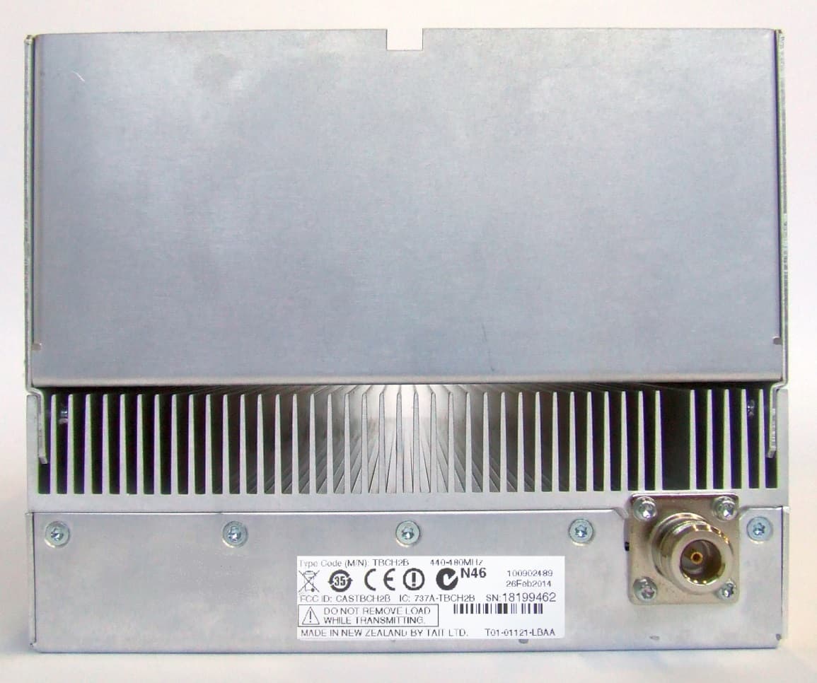
Click to zoom
Application Details
- Equipment Class
- TNB - Licensed Non-Broadcast Station Transmitter
- Date of Grant
- Jul 30, 2014
- Application Purpose
- Original Equipment
- Date of Application
- Jul 30, 2014
- Equipment Note
- Base Station Transceiver
- Frequency Range
- 440.00000000 - 480.00000000
- Company
- Tait International Limited
- Country
- New Zealand
Documents & Files
Document Text
Text extracted from the exhibit documents filed with the FCC. Open a document above to read the original.
Users Manual
TB9400 Installation and Operation ManualInstallation67 © Tait Limited April 2014 5Installation This chapter provides information on the site requirements for your TB9400 equipment and also describes how to install the base station in a standard 19 inch rack or cabinet. If this is your first time installing a TB9400 base station, we recommend that you read the entire chapter before beginning the actual installation. 68InstallationTB9400 Installation and Operation Manual © Tait Limited April 2014 5.1Before You Begin 5.1.1Equipment Security The security of your base station equipment is a high priority. If the site is not fully secure, the base station should at least be locked in a secure cabinet to prevent unauthorized access. 5.1.2Grounding and Lightning Protection Electrical GroundThe base station modules are grounded by physical contact between the module case and the subrack. To ensure a good ground connection you must tighten each module retaining clamp securely (refer to “Final Reassembly” on page 112 for the correct torque). A threaded grounding connector is provided on the rear of the subrack for connection to the site ground point (refer to “Connecting Up the Base Station” on page 88 for more details). Lightning GroundIt is extremely important for the security of the site and its equipment that you take adequate precautions against lightning strike. Because it is outside the scope of this manual to provide comprehensive information on this subject, we recommend that you conform to your country’s standards organization or regulatory body. 5.1.3Equipment Ventilation Always ensure there is adequate ventilation around the base station. NoticeDo not operate it in a sealed cabinet. You must keep the ambient temperature within the specified range, and we strongly rec- ommended that you ensure that the cooling airflow is not restricted. NoticeThe cooling fans are mounted on the front panel and will only operate when the panel is fitted correctly to the front of the subrack. To ensure adequate airflow through the base station, do not operate it for more than a few minutes with the front panel removed (e.g. for servicing purposes). 5.1.4Ambient Temperature Sensor The ambient temperature reading for the base station is provided by the temperature sensor located on the front panel circuit board. TB9400 Installation and Operation ManualInstallation69 © Tait Limited April 2014 5.1.5Cabinet and Rack Ventilation The cooling airflow for the base station enters through the front panel and exits at the rear of the subrack. For optimum thermal performance, the heated air that has passed through a base station must not be allowed to re- enter the air intakes on the front panel. Any space at the front of the cabinet not occupied by equipment should be covered by a blanking panel. Refer toFigure 5.1 on page 70. To allow enough cooling airflow through a cabinet-mounted base station, we recommend the following: ■an area of at least 23 in 2 (150 cm 2 ) of unrestricted ventilation slots or holes in front of the air intakes for the fans for each subrack; for example, thirty 0.25 x 3.3 in (6 x 85 mm) slots will allow the recommended airflow ■a vent in the top of the cabinet with an area of approximately 23 in 2 (150 cm 2 ) per subrack, or a similar area of ventilation per subrack at the rear of the cabinet behind each subrack ■a 2 U gap at the top of the cabinet. NoticeThe ventilation opening must be unrestricted. If the slots or holes are covered with a filter, mesh or grille, the open area must be increased to allow the same airflow as an unrestricted opening. The maximum ambient temperature entering the cabinet must not exceed + 140°F (+ 60°C). If you are installing multiple subracks in a cabinet, ensure that there will be enough cooling airflow through the cabinet after the equipment has been installed. For example, the recommended maximum number of subracks in a 38 U cabinet is five, as shown in Figure 5.1 on page 70. If the base station is installed in a rack or cabinet with other equipment with different ventilation requirements, we recommend that the base station be positioned below this equipment. Auxiliary Extractor Fans The base station does not require auxiliary extractor fans mounted in the top of the cabinet. If your cabinet is already fitted with fans, the following procedures apply: ■if there are six or more 4.75 in (12 cm) fans, each capable of extracting 94.2 ft 3 per minute (160 m 3 per hour), they must run continuously ■if there are fewer than six fans, you must remove them and ensure the vent in the top of the cabinet has an area of approximately 23 in 2 (150 cm 2 ) per subrack. If you have any other configuration, the performance of your system will depend on how closely you comply with the base station airflow requirements described above. 70InstallationTB9400 Installation and Operation Manual © Tait Limited April 2014 Figure 5.1Typical cabinet ventilation requirements b ventilation slots d airflow entry c blanking panels e airflow exit path 8in (20 cm) 2U ≥7in (≥17.5cm) side viewfront view top view c c d e b TB9400 Installation and Operation ManualInstallation71 © Tait Limited April 2014 5.2Unpacking and Moving the Subrack The subrack is packed in a strong corrugated cardboard carton with top and bottom foam cushions. To prevent personal injury and damage to the equipment, we recommend that two people unpack and move the subrack. To remove the subrack from the carton, follow the procedure illustrated in Figure 5.2. CautionA subrack complete with modules can weigh up to 46 lb (21 kg), or up to 53 lb (24 kg) complete with packaging. We recommend that you have another person help you unpack and move the equipment. The TBAA03-16 carrying handles will make it easier to move the equipment once it has been unpacked. If necessary, remove the modules from the subrack before moving it (refer to “Replacing Modules” on page 101). In all cases follow safe lifting practices. 1.Cut the tape securing…
Text truncated - open the document above for the full version.
Users Manual
TB9400 Base Station Installation and Operation Manual MBC-00001-06 · Issue 6· April 2014 2TB9400 Installation and Operation Manual © Tait Limited April 2014 Contact Information Tait Communications Corporate Head Office Tait Limited P.O. Box 1645 Christchurch New Zealand For the address and telephone number of regional offices, refer to our website: www.taitradio.com Copyright and Trademarks All information contained in this document is the property of Tait Limited. All rights reserved. This document may not, in whole or in part, be copied, photocopied, reproduced, translated, stored, or reduced to any electronic medium or machine-readable form, without prior written permission from Tait Limited. The word TAIT and the TAIT logo are trademarks of Tait Limited. All trade names referenced are the service mark, trademark or registered trademark of the respective manufacturers. Disclaimer There are no warranties extended or granted by this document. Tait Limited accepts no responsibility for damage arising from use of the information contained in the document or of the equipment and software it describes. It is the responsibility of the user to ensure that use of such information, equipment and software complies with the laws, rules and regulations of the applicable jurisdictions. Enquiries and Comments If you have any enquiries regarding this document, or any comments, suggestions and notifications of errors, please contact your regional Tait office. Updates of Manual and Equipment In the interests of improving the performance, reliability or servicing of the equipment, Tait Limited reserves the right to update the equipment or this document or both without prior notice. Intellectual Property Rights This product may be protected by one or more patents or designs of Tait Limited together with their international equivalents, pending patent or design applications, and registered trade marks: NZ 409837, NZ 409838, NZ 415277, NZ 415278, NZ 508806, NZ 511155, NZ 516280/NZ 519742, NZ 521450, NZ 524369, NZ 524378, NZ 524509, NZ 524537, NZ 530819, NZ 534475, NZ 534692, NZ 547713, NZ 569985, NZ 577009, NZ 579051, NZ 579364, NZ 580361, NZ 584534, NZ 586889, NZ 592624, NZ 593887, NZ 593888, NZ 600346, NZ 601933 , NZ 607046, NZ 607046, NZ 610426, NZ 610563, NZ 612027, NZ 613565, NZ 615898, NZ 615954, AU 2004216984, AU 321864, AU 321868, AU 339127, AU 339391, CN 1031871, CN 1070368, CN 200930004199.5, CN 200930004200.4, CN 200930009301.0, EU 000915475-0001, EU 000915475-0002, GB 2413445, US 12/870840, US 13/082767, US 13/185498, US 13/465664, US 13/ 542062, US 13/542147, US 13/763531, US 13/896969, US 14/032876, US 29/401234, US 29/401235, US 5745840, US 640974, US 640977, US 7411461, US 7758996, US 7937661, US 8301682. This product may also be made under license under one or more of the following U.S. Patents: 5,146,497, 5,148,482, 5,164,986, 5,185,795, 5,185,796, 5,271,017, 5,377,229 and 5,502,767. The AMBE+2™ voice coding Technology embodied in this product is protected by intellectual property rights including patent rights, copyrights and trade secrets of Digital Voice Systems, Inc. This voice coding Technology is licensed solely for use within this Communications Equipment. The user of this Technology is explicitly prohibited from attempting to decompile, reverse engineer, or disassemble the Object Code, or in any other way convert the Object Code into a human-readable form. Protected by U.S. Patents 5,870,405, 5,826,222, 5,754,974, 5,701,390, 5,715,365, 5,649,050, 5,630,011, 5,581,656, 5,517,511, 5,491,772, 5,247,579, 5,226,084 and 5,195,166. Environmental Responsibilities Tait Limited is an environmentally responsible company which supports waste minimization, material recovery and restrictions in the use of hazardous materials. The European Union’s Waste Electrical and Electronic Equipment (WEEE) Directive requires that this product be disposed of separately from the general waste stream when its service life is over. For more information about how to dispose of your unwanted Tait product, visit the Tait WEEE website at www.taitradio.com/weee. Please be environmentally responsible and dispose through the original supplier, or contact Tait Limited. Tait Limited also complies with the Restriction of the Use of Certain Hazardous Substances in Electrical and Electronic Equipment (RoHS) Directive in the European Union. In China, we comply with the Measures for Administration of the Pollution Control of Electronic Information Products. We will comply with environmental requirements in other markets as they are introduced. TB9400 Installation and Operation Manual3 © Tait Limited April 2014 Contents Preface . . . . . . . . . . . . . . . . . . . . . . . . . . . . . . . . . . . . . . . . . . . . . . . . . . . . . . . . . . . . . . . . . . . . . 7 Scope of Manual. . . . . . . . . . . . . . . . . . . . . . . . . . . . . . . . . . . . . . . . . . . . . . . . . . . . . . . . 7 Document Conventions . . . . . . . . . . . . . . . . . . . . . . . . . . . . . . . . . . . . . . . . . . . . . . . . . . 7 Associated Documentation. . . . . . . . . . . . . . . . . . . . . . . . . . . . . . . . . . . . . . . . . . . . . . . . 8 Publication Record . . . . . . . . . . . . . . . . . . . . . . . . . . . . . . . . . . . . . . . . . . . . . . . . . . . . . . 8 1Description . . . . . . . . . . . . . . . . . . . . . . . . . . . . . . . . . . . . . . . . . . . . . . . . . . . . . . . . . . . . . . 9 1.1 Features . . . . . . . . . . . . . . . . . . . . . . . . . . . . . . . . . . . . . . . . . . . . . . . . . . . . . . . . . 10 1.2 Modules . . . . . . . . . . . . . . . . . . . . . . . . . . . . . . . . . . . . . . . . . . . . . . . . . . . . . . . . . 11 1.3 Mechanical Assembly . . . . . . . . . . . . . . . . . . . . . . . . . . . . . . . . . . . . . . . . . . . . . . 14 1.4 Frequency Bands and Sub-bands . . . . . . . . . . . . . . . . . . . . . . . . . . . . . . . . . . . . . . 17 1.5 Applications . . . . . . . . . . . . . . . . …
Text truncated - open the document above for the full version.
Attestation Statements
Tait Limited Phone: +64 3 358 0403 PO Box 1645, 558 Wairakei Road Fax: +64 3 359 4632 Burnside, Christchurch 8053 www.taitradio.com New Zealand 16 July 2014 Daniel E Crowder Elite Electronic Engineering Inc. 1516 Centre Circle, Downers Grove Illinois 60515 United States of America Dear Dan, Subject: Part 90.203 (j) (5) Certification Statement – FCC ID: TBCH2B Tait Limited certifies that it’s Digital Base Station FCC ID:TBCH2B, meets a spectrum efficiency standard of one voice channel per 6.25 kHz of channel bandwidth. Additionally, Tait Limited certifies the equipment is capable of supporting a minimum data rate of 4800 bits per second per 6.25 kHz of channel bandwidth. Yours sincerely, David Jackson Test Laboratory Services Manager Tait Limited
Cover Letter(s)
Tait Limited Phone: +64 3 357 0283 PO Box 1645, 558 Wairakei Road Fax: +64 3 359 4632 Burnside, Christchurch 8053 www.taitradio.com New Zealand 16 July 2014 Request for Confidentiality FCC ID: CASTBCH2B Pursuant to Sections 0.457 and 0.459 of the Commission’s rules, Tait Limited hereby requests that the following documents be held confidential: • Technical Description (includes Block and Level) • Operational Description • Tune-up Procedure • Schematics • Parts Lists In support of the Request for Confidentiality, the following is stated: Enclosed within this application is technical information which we deem to be trade secrets and proprietary. If made public, the information might be used to our disadvantage. To assist in assuring that we receive the full value of our product and protect its competitive posture, we respectfully request this grant of confidentiality. David Jackson Test Laboratory Services Manager Tait Limited
Cover Letter(s)
Justifi FCC ID: To meet th Range Lis This Base 1. T 2. C fr Programm Frequency Transmiss In addition This devic The Grant Freq. Ra 420-450 450-454 454-455 455-456 456-460 460-462. 462.5375 462.7375 467.5375 467.7375 470-512 NF=Non Fed Des Fox Complian Tait Limi t Christchur 17th July cation Le CASTBCH2 he requiremen stings for Cert e Station Trans The design cap Complies with frequencies us ming this equip y band 406.00 sions should n n to the follow ce may be util t Note ‘EF’ sh ange (MHz) 5375 5-462.7375 5-467.5375 5-467.7375 5-470 deral, F=Federal ce Cordinator ted rch, y 2014 etter – Ex 2B nts of Federal tification Gran smitter has: pability to ope h 47CFR Part sing the norma pment is the re 00 to 406.100 not be made w wing rule parts lised in system hould be appen Part 90 F/NF NF NF NF NF NF NF r xtended Communicati nts, Tait Limit erate in the fre 90.203(e) in t ally accessible esponsibility o 0 MHz is rese within this freq s applied for: ms operated by nded to the Gr Frequenc ions Commiss ted submits th equency band that the equipm e external con of Tait Limite erved for use b quency band. 90 y Federal and rant of Author cy Range sion (F.C.C.) p he following a 440-480 MH ment operator trols. ed approved S by distress bea Public Safety risation, indic e publication, K ttestation. z. r cannot direct ervice Agents acons. y agencies. cating this ope Pag KDB634817 - tly program tr s eration is requ ge 1 of 1 Frequency ransmit uired.
External Photos
Tait Limited 535 Wairakei Road, Christchurch 8053 PO Box 1645 CHCH New Zealand +64 3 358 3399, www.taitradio.com Page 1 of 11 Tait Limited External Photographs Exhibit (July 2014) Product: TB9435-H2M0-0000-A1BA-10 Type code: TBCH2B FCC ID: CASTBCH2B IC: 737A-TBCH2B Tait Limited 535 Wairakei Road, Christchurch 8053 PO Box 1645 CHCH New Zealand +64 3 358 3399, www.taitradio.com Page 2 of 11 Photograph 01: System – Product view Tait Limited 535 Wairakei Road, Christchurch 8053 PO Box 1645 CHCH New Zealand +64 3 358 3399, www.taitradio.com Page 3 of 11 Photograph 02: System – Front panel Tait Limited 535 Wairakei Road, Christchurch 8053 PO Box 1645 CHCH New Zealand +64 3 358 3399, www.taitradio.com Page 4 of 11 Photograph 03: System – Rear panel Tait Limited 535 Wairakei Road, Christchurch 8053 PO Box 1645 CHCH New Zealand +64 3 358 3399, www.taitradio.com Page 5 of 11 Photograph 04: System – Internal view Tait Limited 535 Wairakei Road, Christchurch 8053 PO Box 1645 CHCH New Zealand +64 3 358 3399, www.taitradio.com Page 6 of 11 Photograph 05: PA module – Product view Tait Limited 535 Wairakei Road, Christchurch 8053 PO Box 1645 CHCH New Zealand +64 3 358 3399, www.taitradio.com Page 7 of 11 Photograph 06: Reciter module – Product view Tait Limited 535 Wairakei Road, Christchurch 8053 PO Box 1645 CHCH New Zealand +64 3 358 3399, www.taitradio.com Page 8 of 11 Photograph 07: PA module – Front panel Tait Limited 535 Wairakei Road, Christchurch 8053 PO Box 1645 CHCH New Zealand +64 3 358 3399, www.taitradio.com Page 9 of 11 Photograph 08: PA module – Rear panel Tait Limited 535 Wairakei Road, Christchurch 8053 PO Box 1645 CHCH New Zealand +64 3 358 3399, www.taitradio.com Page 10 of 11 Photograph 09: Reciter module – Front panel Tait Limited 535 Wairakei Road, Christchurch 8053 PO Box 1645 CHCH New Zealand +64 3 358 3399, www.taitradio.com Page 11 of 11 Photograph 10: Reciter module – Rear panel
ID Label/Location Info
Tait Limited 535 Wairakei Road, Christchurch 8053 PO Box 1645 CHCH New Zealand +64 3 358 3399, www.taitradio.com Page 1 of 3 Tait Limited Compliance Label Photograph Exhibit (July 2014) Product: TB9435-H2M0-0000-A1BA-10 Type code: TBCH2B FCC ID: CASTBCH2B IC: 737A-TBCH2B Tait Limited 535 Wairakei Road, Christchurch 8053 PO Box 1645 CHCH New Zealand +64 3 358 3399, www.taitradio.com Page 2 of 3 Photograph 01: 100W System – Product ID label Tait Limited 535 Wairakei Road, Christchurch 8053 PO Box 1645 CHCH New Zealand +64 3 358 3399, www.taitradio.com Page 3 of 3 Photograph 02: Reciter module – Compliance label Photograph 03: 100W PA module – Compliance label
Internal Photos
Tait Limited 535 Wairakei Road, Christchurch 8053 PO Box 1645 CHCH New Zealand +64 3 358 3399, www.taitradio.com Page 1 of 24 Tait Limited Internal Photographs Exhibit (July 2014) Product: TB9435-H2M0-0000-A1BA-10 Type code: TBCH2B FCC ID: CASTBCH2B IC: 737A-TBCH2B Tait Limited 535 Wairakei Road, Christchurch 8053 PO Box 1645 CHCH New Zealand +64 3 358 3399, www.taitradio.com Page 2 of 24 Photograph 01: 100W PA module – Internal view Tait Limited 535 Wairakei Road, Christchurch 8053 PO Box 1645 CHCH New Zealand +64 3 358 3399, www.taitradio.com Page 3 of 24 Photograph 02: PA Driver PCB - Top Tait Limited 535 Wairakei Road, Christchurch 8053 PO Box 1645 CHCH New Zealand +64 3 358 3399, www.taitradio.com Page 4 of 24 Photograph 03: PA Driver PCB - Bottom Tait Limited 535 Wairakei Road, Christchurch 8053 PO Box 1645 CHCH New Zealand +64 3 358 3399, www.taitradio.com Page 5 of 24 Photograph 04: 100W PA PCB – Top Tait Limited 535 Wairakei Road, Christchurch 8053 PO Box 1645 CHCH New Zealand +64 3 358 3399, www.taitradio.com Page 6 of 24 Photograph 05: 50W PA PCB - Bottom Tait Limited 535 Wairakei Road, Christchurch 8053 PO Box 1645 CHCH New Zealand +64 3 358 3399, www.taitradio.com Page 7 of 24 Photograph 06: PA Control PCB - Top Tait Limited 535 Wairakei Road, Christchurch 8053 PO Box 1645 CHCH New Zealand +64 3 358 3399, www.taitradio.com Page 8 of 24 Photograph 07: PA Control PCB – Bottom Tait Limited 535 Wairakei Road, Christchurch 8053 PO Box 1645 CHCH New Zealand +64 3 358 3399, www.taitradio.com Page 9 of 24 Photograph 08: PA LPF PCB – Top Tait Limited 535 Wairakei Road, Christchurch 8053 PO Box 1645 CHCH New Zealand +64 3 358 3399, www.taitradio.com Page 10 of 24 Photograph 09: PA LPF PCB – Bottom Tait Limited 535 Wairakei Road, Christchurch 8053 PO Box 1645 CHCH New Zealand +64 3 358 3399, www.taitradio.com Page 11 of 24 Photograph 10: Reciter module – Internal (Receiver PCB side) Tait Limited 535 Wairakei Road, Christchurch 8053 PO Box 1645 CHCH New Zealand +64 3 358 3399, www.taitradio.com Page 12 of 24 Photograph 11: Reciter module – Internal (Control PCB side) Tait Limited 535 Wairakei Road, Christchurch 8053 PO Box 1645 CHCH New Zealand +64 3 358 3399, www.taitradio.com Page 13 of 24 Photograph 12: Reciter Control PCB – Top (with shields) Tait Limited 535 Wairakei Road, Christchurch 8053 PO Box 1645 CHCH New Zealand +64 3 358 3399, www.taitradio.com Page 14 of 24 Photograph 13: Reciter Control PCB – Top (without shields) Tait Limited 535 Wairakei Road, Christchurch 8053 PO Box 1645 CHCH New Zealand +64 3 358 3399, www.taitradio.com Page 15 of 24 Photograph 14: Reciter Control PCB – Bottom Tait Limited 535 Wairakei Road, Christchurch 8053 PO Box 1645 CHCH New Zealand +64 3 358 3399, www.taitradio.com Page 16 of 24 Photograph 15: Reciter Receiver PCB – Top (with shields) Tait Limited 535 Wairakei Road, Christchurch 8053 PO Box 1645 CHCH New Zealand +64 3 358 3399, www.taitradio.com Page 17 of 24 Photograph 16: Reciter Receiver PCB – Top (without shields) Tait Limited 535 Wairakei Road, Christchurch 8053 PO Box 1645 CHCH New Zealand +64 3 358 3399, www.taitradio.com Page 18 of 24 Photograph 17: Reciter Receiver PCB – Bottom Tait Limited 535 Wairakei Road, Christchurch 8053 PO Box 1645 CHCH New Zealand +64 3 358 3399, www.taitradio.com Page 19 of 24 Photograph 18: Reciter TXF PCB – Top (with shields) Tait Limited 535 Wairakei Road, Christchurch 8053 PO Box 1645 CHCH New Zealand +64 3 358 3399, www.taitradio.com Page 20 of 24 Photograph 19: Reciter TXF PCB – Top (without shields) Tait Limited 535 Wairakei Road, Christchurch 8053 PO Box 1645 CHCH New Zealand +64 3 358 3399, www.taitradio.com Page 21 of 24 Photograph 20: Reciter TXF PCB – Bottom Tait Limited 535 Wairakei Road, Christchurch 8053 PO Box 1645 CHCH New Zealand +64 3 358 3399, www.taitradio.com Page 22 of 24 Photograph 21: Reciter TXR PCB – Top (with shields) Tait Limited 535 Wairakei Road, Christchurch 8053 PO Box 1645 CHCH New Zealand +64 3 358 3399, www.taitradio.com Page 23 of 24 Photograph 22: Reciter TXR PCB – Top (without shields) Tait Limited 535 Wairakei Road, Christchurch 8053 PO Box 1645 CHCH New Zealand +64 3 358 3399, www.taitradio.com Page 24 of 24 Photograph 23: Reciter TXR PCB: Bottom
RF Exposure Info
Page 1 of 5 RF Exposure Technical Brief Supplementary to Teltest report 3587 Equipment: TBCH2B Base Station Transceiver IC identification 737A-TBCH2B Rated transmit power: 100W Frequency range: 450 470 MHz Test standard: RSS102 issue 4 Reference Standard: IEEE C95.3 -2002 Contents RSS102 Annex A - RF Technical Brief Cover Sheet .......................................................... 2 RSS102 Annex B - Declaration of RF Exposure Compliance ............................................ 3 Safe Distance calculations – Uncontrolled environment .................................................... 4 Minimum distance requirement stated in the user manual ................................................. 5 References: ....................................................................................................................... 5 Page 2 of 5 RSS102 Annex A - RF Technical Brief Cover Sheet All Fields must be completed with the requested information or the following codes: N/A for Not Applicable, N/P for Not Performed or N/V for Not Available. Where applicable, check appropriate box. 1. COMPANY NUMBER: 737A 2. MODEL NUMBER: TBCH2B 3. MANUFACTURER: Tait Communications 4. TYPE OF EVALUATION: (d) RF Exposure Evaluation.) Note: The worst-case scenario (i.e. highest measured value obtained) shall be reported. (a) SAR Evaluation: Device Used in the Vicinity of the Human Head ● Multiple transmitters: Yes □ No □ ● Evaluated against exposure limits: General Public Use □ Controlled Use □ ● Duty cycle used in evaluation: ____N/A______% ● Standard used for evaluation: _______ N/A __________________ ● SAR value: ___ N/A ___W/kg Measured □ Computed □ Calculated □ (b) SAR Evaluation: Body-Worn Device and Body-Supported Device ● Multiple transmitters: Yes □ No □ ● Evaluated against exposure limits: General Public Use □ Controlled Use □ ● Duty cycle used in evaluation: ___ N/A ___% ● Standard used for evaluation: ____ N/A _____________ ● SAR value: __ N/A ____W/kg Measured □ Computed □ Calculated □ (c) SAR Evaluation: Limb-Worn Device ● Multiple transmitters: Yes □ No □ ● Evaluated against exposure limits: General Public Use □ Controlled Use □ ● Duty cycle used in evaluation: __ N/A ____% ● Standard used for evaluation: ____ N/A __________________ ● SAR value: __ N/A _____W/kg Measured □ Computed □ Calculated □ (d) RF Exposure Evaluation ● Evaluated against exposure limits: General Public Use Controlled Use ● Duty cycle used in evaluation: 100 % ● Standard used for evaluation: IEEE C95.3 -2002 ● Measurement distance: 3.6 m ● RF field strength value: 2.0 V/m □ A/m □ W/m2 Measured □ Computed □ Calculated Page 3 of 5 RSS102 Annex B - Declaration of RF Exposure Compliance ATTESTATION: I attest that the information provided in Annex A is correct; that the Technical Brief was prepared and the information contained therein is correct; that the device evaluation was performed or supervised by me; that applicable measurement methods and evaluation methodologies have been followed; and that the device meets the SAR and/or RF field strength limits of RSS-102. Signature: Date: 17 July 2014 NAME: Mike James TITLE: Laboratory Technical Manager COMPANY: Teltest Laboratories Tait Communications Page 4 of 5 Safe Distance calculations – Uncontrolled environment Transmitter power : 100W Antenna Type: Dual dipole array, Vertically polarised Antenna Gain: 5.1dBi Antenna Length: 1.0m Calculation frequency: 450MHz RF Field Strength limit for uncontrolled environments (RSS102 table 4.2) 300MHz to 1500MHz Limit = f/150 Wm 2 = 450/150 =3.0 W/m 2 Near field Calculation Equation 39 of IEEE C93.3-2002 ܵ = ܲ (2 ߨ ݀ ℎ) Rearranged to find d ݀= ܲ (2 ߨ ܵ ℎ) For 100W ݀= 100 2ߨ×2.67×1 =5.31݉ Fresnel region and far field calculation Equation 37 of IEEE C93.3-2002 ܵ = ܲ ܩ 4 ߨ ݀ ଶ Rearranged to find d ݀= ඨ ܲ ܩ 4 ߨ ܵ For 100W ݀= ඨ 100 × 3.24 4 ߨ ×2.67 =2.93݉ Page 5 of 5 Far Field boundary calculation The near field equation may be applied for several metres from the antenna, but may over predict the power density at longer distances. To determine which result should be used the crossover point where the predicted field strengths are the same is calculated. ܵ =ܵ ܲ ( 2 ߨ ݀ ℎ ) = ܲ ܩ 4 ߨ ݀ ଶ Rearranged to find d ݀= ܩℎ 2 ݀= 3.24 ×1.2 2 = 3.24 ×1.2 2 =1.62݉ For a 1.0m antenna at 450MHz, the crossover point is 1.62m. Therefore the far-field calculation is appropriate and the minimum safe distance for the general public is 2.93m. Minimum distance requirement stated in the user manual For convenience the derived figure of 1.62m is rounded up to 3.6m giving the following for 100W ܵ= 100 ×3.24 4 ߨ 3.6 ଶ =2.0 ܹ/݉ ଶ Where: S=power density in W/m 2 P= net power output to the antenna (W) d = radius of a cylinder around the antenna (m) h = aperture height of antenna (m) G = linear gain of antenna relative to an isotropic radiator (5.1dBi = 3.24 linear terms) F = frequency (MHz) References: 1. RSS102 issue 4 March 2010 Radio Frequency (RF) Exposure Compliance of Radiocommunication Apparatus (All Frequency Bands) 2. IEEE Std C95.3-2002 IEEE Recommended Practice for Measurements and Computations of Radio Frequency End
Test Report
TELTEST Laboratories Tait Ltd Report Number 3587 FCC ID: CASTBCH2B Page 1 of 37 Report Revision: 1 IC: 737A-TBCH2B Issue Date: 21-July-2014 LABORATORY TEST REPORT RADIO PERFORMANCE MEASUREMENTS for the TBCH2B Base Station Transceiver Tested in accordance with: FCC 47 CFR Part 90 RSS-119 Issue 11 RSS-Gen Issue 3 Report Revision: 1 Issue Date: 21 July 2014 PREPARED BY: L. M. White _______________ Test Technician CHECKED & APPROVED BY: M. C. James _______________ Laboratory Technical Manager OATS FCC LISTING REGISTRATION: 837095 OATS IC LISTING REGISTRATION: SITE# 737A-1 All tests reported herein have been performed in accordance with the laboratory's scope of accreditation. This document must not be reproduced except in full, without the written permission of the Compliance Laboratory Manager TELTEST Laboratories (A Division of Tait Communications) Telephone: 64 3 358 3399 PO Box 1645, 558 Wairakei Road, Christchurch, New Zealand. FAX: 64 3 359 4632 TELTEST Laboratories Tait Ltd Report Number 3587 FCC ID: CASTBCH2B Page 2 of 37 Report Revision: 1 IC: 737A-TBCH2B Issue Date: 21-July-2014 TABLE OF CONTENTS REVISION .................................................................................................................. 3 INTRODUCTION ........................................................................................................ 4 STATEMENT OF COMPLIANCE ............................................................................... 5 MODULATION TYPES, NECESSARY BANDWIDTH & EMISSION DESIGNATORS 6 TEST RESULTS ......................................................................................................... 8 TRANSMITTER OUTPUT POWER (CONDUCTED) .............................................. 8 TRANSMITTER OCCUPIED BANDWIDTH AND SPECTRUM MASKS ................. 9 TRANSMITTER SPURIOUS EMISSIONS (CONDUCTED) .................................. 14 TRANSMITTER SPURIOUS EMISSIONS (RADIATED) ....................................... 22 TRANSIENT FREQUENCY BEHAVIOR ............................................................... 25 TRANSMITTER FREQUENCY STABILITY - TEMPERATURE ............................ 30 TRANSMITTER FREQUENCY STABILITY - VOLTAGE ...................................... 32 RECEIVER SPURIOUS EMISSIONS (CONDUCTED) ......................................... 33 TRANSMITTER STANDBY SPURIOUS EMISSIONS (CONDUCTED) ................ 34 TEST EQUIPMENT LIST.......................................................................................... 35 ANNEX A – TEST SETUP DETAILS ........................................................................ 37 TELTEST Laboratories Tait Ltd Report Number 3587 FCC ID: CASTBCH2B Page 3 of 37 Report Revision: 1 IC: 737A-TBCH2B Issue Date: 21-July-2014 REVISION Date Revision Comments 21 July 2014 1 Initial test report TELTEST Laboratories Tait Ltd…
Text truncated - open the document above for the full version.
Contact Information
Applicant
Linda White(Standards and Regulatory Manager)
Technical Specifications
| # | Rule Parts | Frequency Range | Power Output | Emission | Tolerance |
|---|---|---|---|---|---|
| 6 | 9 | 440 MHz - 480 MHz | 100 W | 9K80D7W | 0.5 ppm |
Other Applications from Tait International Limited
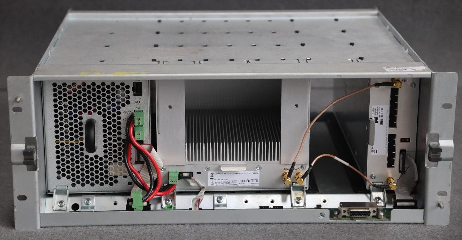
CASTBCHGB
May 12, 2026Base Station Transceiver
Equipment Class
TNB - Licensed Non-Broadcast Station Transmitter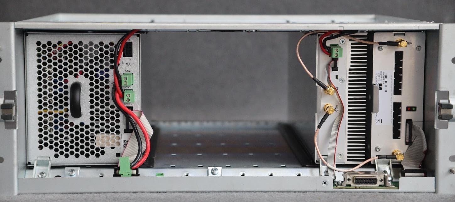
CASTBCHGA
May 12, 2026Base Station Transceiver
Equipment Class
TNB - Licensed Non-Broadcast Station Transmitter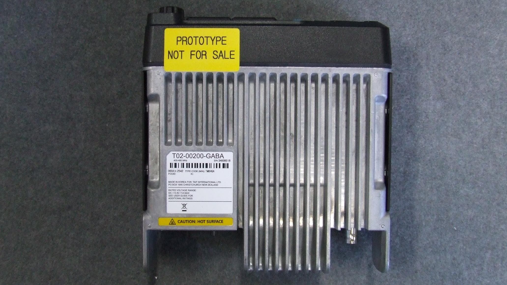
CASTMDHGA
Feb 04, 2026Mobile Transceiver
Equipment Class
TNB - Licensed Non-Broadcast Station Transmitter
CASTPJHGB
Jan 15, 2026Portable Transceiver
Equipment Class
TNF - Licensed Non-Broadcast Transmitter Held to Face
CASTPJHGA
Jan 15, 2026Portable Transceiver
Equipment Class
DSS - Part 15 Spread Spectrum Transmitter