CASTBCK4EBasestation Transceiver
Tait International Limited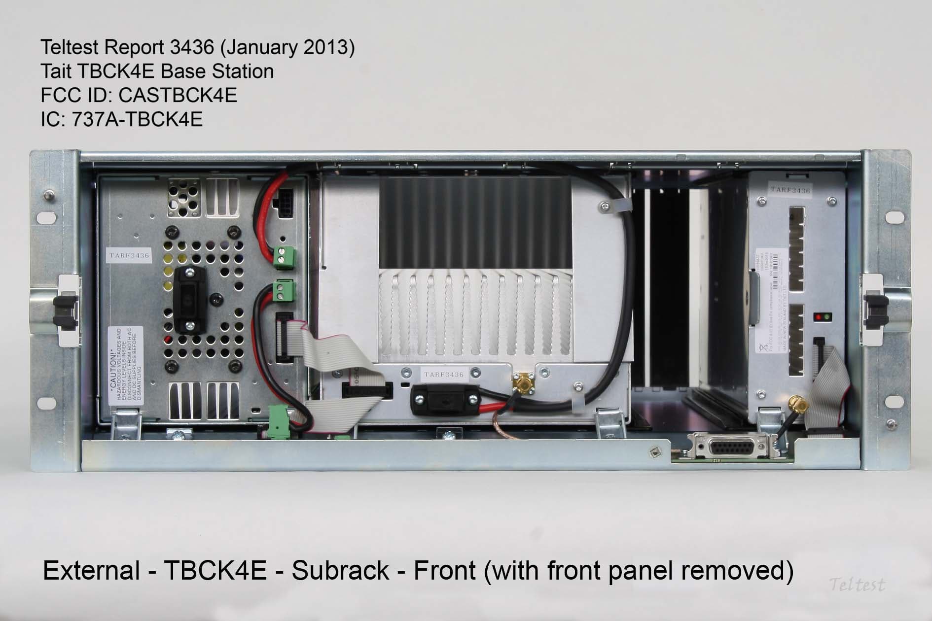
Click to zoom
Application Details
- Equipment Class
- TNB - Licensed Non-Broadcast Station Transmitter
- Date of Grant
- Feb 04, 2013
- Application Purpose
- Original Equipment
- Date of Application
- Feb 04, 2013
- Equipment Note
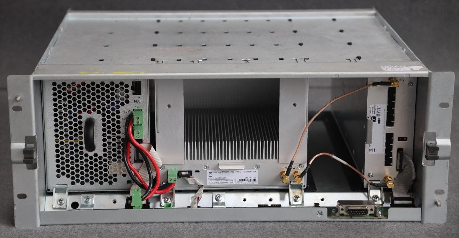
- Basestation Transceiver
- Frequency Range
- 851.00000000 - 869.00000000
- Company
- Tait International Limited
- Country
- New Zealand
Documents & Files
Document Text
Text extracted from the exhibit documents filed with the FCC. Open a document above to read the original.
Users Manual
TB9300 Installation and Operation ManualInstallation61 © Tait Limited July 2012 5Installation This chapter provides information on the site requirements for your TB9300 equipment and also describes how to install the base station in a standard 19 inch rack or cabinet. If this is your first time installing a TB9300 base station, we recommend that you read the entire chapter before beginning the actual installation. 5.1Before You Begin 5.1.1Equipment Security The security of your base station equipment is a high priority. If the site is not fully secure, the base station should at least be locked in a secure cabinet to prevent unauthorized access. 5.1.2Grounding and Lightning Protection Electrical GroundThe base station modules are grounded by physical contact between the module case and the subrack. To ensure a good ground connection you must tighten each module retaining clamp securely (refer to “Final Reassembly” on page 102 for the correct torque). A threaded grounding connector is provided on the rear of the subrack for connection to the site ground point (refer to “Connecting Up the Base Station” on page 79 for more details). Lightning GroundIt is extremely important for the security of the site and its equipment that you take adequate precautions against lightning strike. Because it is outside the scope of this manual to provide comprehensive information on this subject, we recommend that you conform to your country’s standards organization or regulatory body. 62InstallationTB9300 Installation and Operation Manual © Tait Limited July 2012 5.1.3Equipment Ventilation Always ensure there is adequate ventilation around the base station. NoticeDo not operate it in a sealed cabinet. You must keep the ambient temperature within the specified range, and we strongly rec- ommended that you ensure that the cooling airflow is not restricted. NoticeThe cooling fans are mounted on the front panel and will only operate when the panel is fitted correctly to the front of the subrack. To ensure adequate airflow through the base station, do not operate it for more than a few minutes with the front panel removed (e.g. for servicing purposes). 5.1.4Ambient Temperature Sensor The ambient temperature reading for the base station is provided by the temperature sensor located on the front panel circuit board. TB9300 Installation and Operation ManualInstallation63 © Tait Limited July 2012 5.1.5Cabinet and Rack Ventilation The cooling airflow for the base station enters through the front panel and exits at the rear of the subrack. For optimum thermal performance, the heated air that has passed through a base station must not be allowed to re- enter the air intakes on the front panel. Any space at the front of the cabinet not occupied by equipment should be covered by a blanking panel. Refer toFigure 5.1 on page 64. To allow enough cooling airflow through a cabinet-mounted base station, we recommend the following: ■an area of at least 23 in 2 (150 cm 2 ) of unrestricted ventilation slots or holes in front of the air intakes for the fans for each subrack; for example, thirty 0.25 x 3.3 in (6 x 85 mm) slots will allow the recommended airflow ■a vent in the top of the cabinet with an area of approximately 23 in 2 (150 cm 2 ) per subrack, or a similar area of ventilation per subrack at the rear of the cabinet behind each subrack ■a 2 U gap at the top of the cabinet. NoticeThe ventilation opening must be unrestricted. If the slots or holes are covered with a filter, mesh or grille, the open area must be increased to allow the same airflow as an unrestricted opening. The maximum ambient temperature entering the cabinet must not exceed + 140°F (+ 60°C). If you are installing multiple subracks in a cabinet, ensure that there will be enough cooling airflow through the cabinet after the equipment has been installed. For example, the recommended maximum number of subracks in a 38 U cabinet is five, as shown in Figure 5.1 on page 64. If the base station is installed in a rack or cabinet with other equipment with different ventilation requirements, we recommend that the base station be positioned below this equipment. Auxiliary Extractor Fans The base station does not require auxiliary extractor fans mounted in the top of the cabinet. If your cabinet is already fitted with fans, the following procedures apply: ■if there are six or more 4.75 in (12 cm) fans, each capable of extracting 94.2 ft 3 per minute (160 m 3 per hour), they must run continuously ■if there are fewer than six fans, you must remove them and ensure the vent in the top of the cabinet has an area of approximately 23 in 2 (150 cm 2 ) per subrack. If you have any other configuration, the performance of your system will depend on how closely you comply with the base station airflow requirements described above. 64InstallationTB9300 Installation and Operation Manual © Tait Limited July 2012 Figure 5.1Typical cabinet ventilation requirements b ventilation slots d airflow entry c blanking panels e airflow exit path 8in (20 cm) 2U ≥7in (≥17.5cm) side viewfront view top view c c d e b TB9300 Installation and Operation ManualInstallation65 © Tait Limited July 2012 5.2Unpacking and Moving the Subrack The subrack is packed in a strong corrugated cardboard carton with top and bottom foam cushions. To prevent personal injury and damage to the equipment, we recommend that two people unpack and move the subrack. To remove the subrack from the carton, follow the procedure illustrated in Figure 5.2. CautionA subrack complete with modules can weigh up to 62 lb (28 kg), or up to 66 lb (30 kg) complete with packaging. We recommend that you have another person help you unpack and move the equipment. The TBAA03-16 carrying handles will make it easier to move the equipment once it has been unpacked. If necessary, remove the modules from the subrack before moving it (refer to “Replacing Modules” on page 91). In all cases follow safe lifting practices. 1.Cut the tape securing the f…
Text truncated - open the document above for the full version.
Cover Letter(s)
Tait Limited Phone: +64 3 358 6635 PO Box 1645, 558 Wairakei Road Fax: +64 3 359 4632 Burnside, Christchurch 8053 www.taitradio.com New Zealand 29 th January 2013 Request for Confidentiality FCC ID: CASTBCK4E Pursuant to Sections 0.457 and 0.459 of the Commission’s rules, Tait Limited hereby requests that the following documents be held confidential: • Technical Description (includes Block and Level) • Operational Description • Tune-up Procedure • Schematics • Parts Lists In support of the Request for Confidentiality, the following is stated: Enclosed within this application is technical information which we deem to be trade secrets and proprietary. If made public, the information might be used to our disadvantage. To assist in assuring that we receive the full value of our product and protect its competitive posture, we respectfully request this grant of confidentiality. Steve Crompton Compliance Laboratory Manager Tait Limited
Cover Letter(s)
Tait Limited Phone: +64 3 358 1026 PO Box 1645, 558 Wairakei Road Fax: +64 3 359 4632 Burnside, Christchurch 8140 www.taitradio.com New Zealand F.C.C. Justification Letter FCC ID: CASTBCK4E To meet the requirements of Federal Communications Commission (F.C.C.) publication, KDB634817 - Frequency Range Listings for Certification Grants, Tait Electronics Limited submits the following attestation. This base station transceiver has: 1. The design capability to operate in the frequency band 762-870 MHz. 2. Complies with 47CFR Part 90.203(e) in that the equipment operator cannot directly program transmit frequencies using the normally accessible external controls. Programming this equipment is the responsibility of Tait Limited approved Service Agents In addition to the following rule parts applied for: Part 90 This device may be utilised in systems operated by Non Federal and Public Safety agencies, as indicated in the table beneath. The Grant Note ‘EF’ should be appended to the Grant of Authorisation, indicating this operation is required. Table 1 – Frequency Range and Rule Parts - (47CFR Part 2.106) Freq. Range (MHz) Part 90 769-775 NF 775-799 799-805 805-806 806-809 809-824 824-851 851-854 NF 854-869 NF NF=Non Federal Agency Des Fox Compliance Coordinator Christchurch 29 th January 2013
Cover Letter(s)
Tait Limited Phone: +64 3 358 0403 PO Box 1645, 558 Wairakei Road Fax: +64 3 359 4632 Burnside, Christchurch 8053 www.taitradio.com New Zealand 29 January 2013 Daniel E Crowder Elite Electronic Engineering Inc. 1516 Centre Circle, Downers Grove Illinois 60515 United States of America Dear Dan, Subject: Part 90.203 (j) (5) Certification Statement – FCC ID: CASTBCK4E Tait Limited certifies that it’s digital base station transceiver FCC ID: CASTBCK4E, meets a spectrum efficiency standard of one voice channel per 6.25 kHz of channel bandwidth. Additionally, Tait Limited certifies the equipment is capable of supporting a minimum data rate of 4800 bits per second per 6.25 kHz of channel bandwidth. Yours sincerely, Brian Emmett Standards and Compliance Engineer
Test Report
TELTEST Laboratories Tait Communications Report Number 3436 FCC ID: CASTBCK4E Page 1 of 43 Report Revision: 1 IC : 737A-TBCK4E Issue Date: 23-January-2013 LABORATORY TEST REPORT RADIO PERFORMANCE MEASUREMENTS for the TBCK4E Base Station Transceiver Tested in accordance with: FCC 47 CFR Parts 90 RSS-119 Issue 11 RSS-Gen Issue 3 Report Revision: 1 Issue Date: 23-01-13 PREPARED BY: Robin Kidson _______________ Test Technician CHECKED & APPROVED BY: Steve Crompton _______________ Laboratory Manager All tests reported herein have been performed in accordance with the laboratory's scope of accreditation. This document must not be reproduced except in full, without the written permission of the Compliance Laboratory Manager TELTEST Laboratories (A Division of Tait Communications) Telephone: 64 3 358 3399 PO Box 1645, 558 Wairakei Road, Christchurch, New Zealand. FAX: 64 3 359 4632 TELTEST Laboratories Tait Communications Report Number 3436 FCC ID: CASTBCK4E Page 2 of 43 Report Revision: 1 IC : 737A-TBCK4E Issue Date: 23-January-2013 TABLE OF CONTENTS REVISION .................................................................................................................. 3 INTRODUCTION ........................................................................................................ 4 STATEMENT OF COMPLIANCE ............................................................................... 6 MODULATION TYPES, NECESSARY BANDWIDTH & EMISSION DESIGNATORS 7 TEST RESULTS ......................................................................................................... 8 TRANSMITTER OUTPUT POWER (CONDUCTED) .............................................. 8 ADJACENT CHANNEL POWER RATIO ................................................................. 9 TRANSMITTER OCCUPIED BANDWIDTH AND SPECTRUM MASKS ............... 10 TRANSMITTER SPURIOUS EMISSIONS (CONDUCTED) .................................. 19 TRANSMITTER SPURIOUS EMISSIONS (RADIATED) ....................................... 22 TRANSMITTER FREQUENCY STABILITY - TEMPERATURE ............................ 26 TRANSMITTER FREQUENCY STABILITY - VOLTAGE ...................................... 30 SPURIOUS EMISSIONS (TX STANDBY / RX CONDUCTED) ............................. 31 TEST EQUIPMENT LIST.......................................................................................... 33 ANNEX A – TEST SETUP DETAILS ........................................................................ 34 ANNEX B – TX CONDUCTED EMISSION PLOTS .................................................. 35 ANNEX C – TX STANDBY / RX CONDUCTED EMISSION PLOTS ........................ 41 TELTEST Laboratories Tait Communications Report Number 3436 FCC ID: CASTBCK4E Page 3 of 43 Report Revision: 1 IC : 737A-TBCK4E Issue Date: 23-January-2013 REVISION Date Revision Comments 23-01-13 1 Initial test report TELTEST Laboratories Tait Communications Report Number 3436 FCC ID: CASTBCK4E Page 4 of 43 Report Revision: 1 IC : 737A-TBCK4E Issue Date: 23-January-2013 INTRODUCTION This report covers the requirements of FCC 47 Parts 90 and RSS-119 Issue 11 & RSS-Gen Issue 3. REASON FOR REPORT The TB9300 K4 100W Base Station is a new addition to the Tait Ltd product line capable of Digital Mobile Radio (DMR) modulation. DMR supports two voice channels in each 12.5 kHz channel. Type Approval Testing of the TBCK4E, Frequency ranges: TX: 762 Æ 776 MHz, 850 Æ 870 MHz and RX: 794 Æ 824 MHz. in accordance with: FCC 47 CFR Parts 90 RSS-119 Issue 11 & RSS-Gen Issue 3 REPORT PREPARED FOR Tait Communications PO Box 1645 558 Wairakei Road Christchurch New Zealand DESCRIPTION OF SAMPLE Manufacturer Tait Limited Equipment: Base Station Transceiver Type: TBCK4E TBCK4E Base Station Transceiver consisting of: FUNCTIONAL DESCRIPTION PRODUCT DESIGNATION CODE SERIAL NUMBER (S) Reciter T01-01105-NAAA 18167383 Power Amplifier T01-01136-NBAA 18167214 Power Management Unit TBA30A0-0100 18167103 Front Panel T01-01110-CCAA 18167400 Sub Rack T01-01101-EAAA 18167399 Quantity: 1 of each TELTEST Laboratories Tait Communications Report Number 3436 FCC ID: CASTBCK4E Page 5 of 43 Report Revision: 1 IC : 737A-TBCK4E Issue Date: 23-January-2013 HARDWARE & SOFTWARE Details: FUNCTIONAL DESCRIPTION FIRMWARE VERSION HARDWARE VERSION Reciter Dmr-1.05.00.0011 00.00 Power Amplifier 0312 00.02 Power Management Unit 0314 00.03 Front Panel 1.02.00.0004 00.04 TEST CONDITIONS All testing was performed between 28 December 2012 Æ 16 January 2013, and under the following conditions: Ambient temperature: 15 o C Æ 30 o C Relative Humidity: 20% Æ 75% Standard Test Voltage 120 Vac Test Frequency pair 769.06875 MHz (TX) / 799.08675 MHz (RX): An external 10 MHz Frequency Reference was used (excluding Radiated Emissions). TELTEST Laboratories Tait Communications Report Number 3436 FCC ID: CASTBCK4E Page 6 of 43 Report Revision: 1 IC : 737A-TBCK4E Issue Date: 23-January-2013 STATEMENT OF COMPLIANCE We, TELTEST LABORATORIES of 558 Wairakei Road, Christchurch New Zealand, declare under our sole responsibility that the product: Equipment: BASE STATION Transceiver Type: TBCK4E Product Code: T01-01131-0007 Serial Number(s): 18167383 Quantity: 1 to which this declaration relates, is in conformity with the following standards: FCC 47 CFR Parts 90 RSS-119 Issue 11 & RSS-Gen Issue 3 Signature: ___________________ S.A. Crompton Compliance Laboratory Manager Date: ___________________ TELTEST Laboratories Tait Communications Report Number 3436 FCC ID: CASTBCK4E Page 7 of 43 Report Revision: 1 IC : 737A-TBCK4E Issue Date: 23-January-2013 MODULATION TYPES, NECESSARY BANDWIDTH & EMISSION DESIGNATORS MODULATION TYPES: 4 Level FSK (as per ETSI TS 102 361-1) 4800 symbols/sec 9600 bps CHANNEL SPACING: 12.5 kHz NECESSARY BANDWIDTH: The necessary bandwidth has been measured using the 99% energy rule, and in accordance with TIA/EIA 102 CAAB 2.2.5.2 and RSS-Gen 4.6.1 99% bandwidth = 7.6 kHz EMISSION DESIGNATORS: DMR Digital Voice / Data 7K60FXW DMR Digital Data 7K60FXD FXW…
Text truncated - open the document above for the full version.
Contact Information
Applicant
Linda White(Standards and Regulatory Manager)
Technical Contact
Tait LimitedStephen A Crompton
[email protected]6433586635
535 Wairakei Road · Christchurch · New Zealand
Non-Technical Contact
Tait LimitedStephen A Crompton
[email protected]6433586635
Technical Specifications
| # | Rule Parts | Frequency Range | Power Output | Emission | Tolerance |
|---|---|---|---|---|---|
| 4 | 9 | 851 MHz - 869 MHz | 100 W | 7K60FXD | 0.1 ppm |
Other Applications from Tait International Limited
CASTBCHGB
May 12, 2026Base Station Transceiver
Equipment Class
TNB - Licensed Non-Broadcast Station Transmitter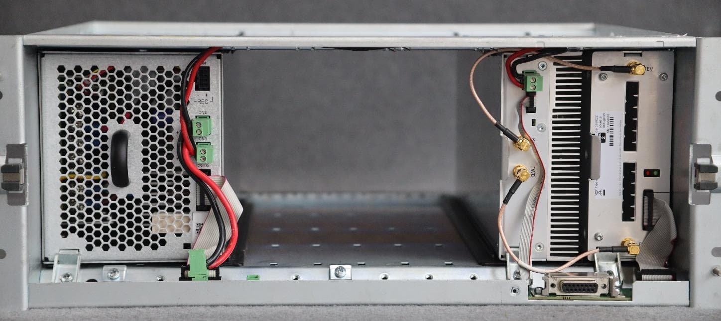
CASTBCHGA
May 12, 2026Base Station Transceiver
Equipment Class
TNB - Licensed Non-Broadcast Station Transmitter
CASTMDHGA
Feb 04, 2026Mobile Transceiver
Equipment Class
TNB - Licensed Non-Broadcast Station Transmitter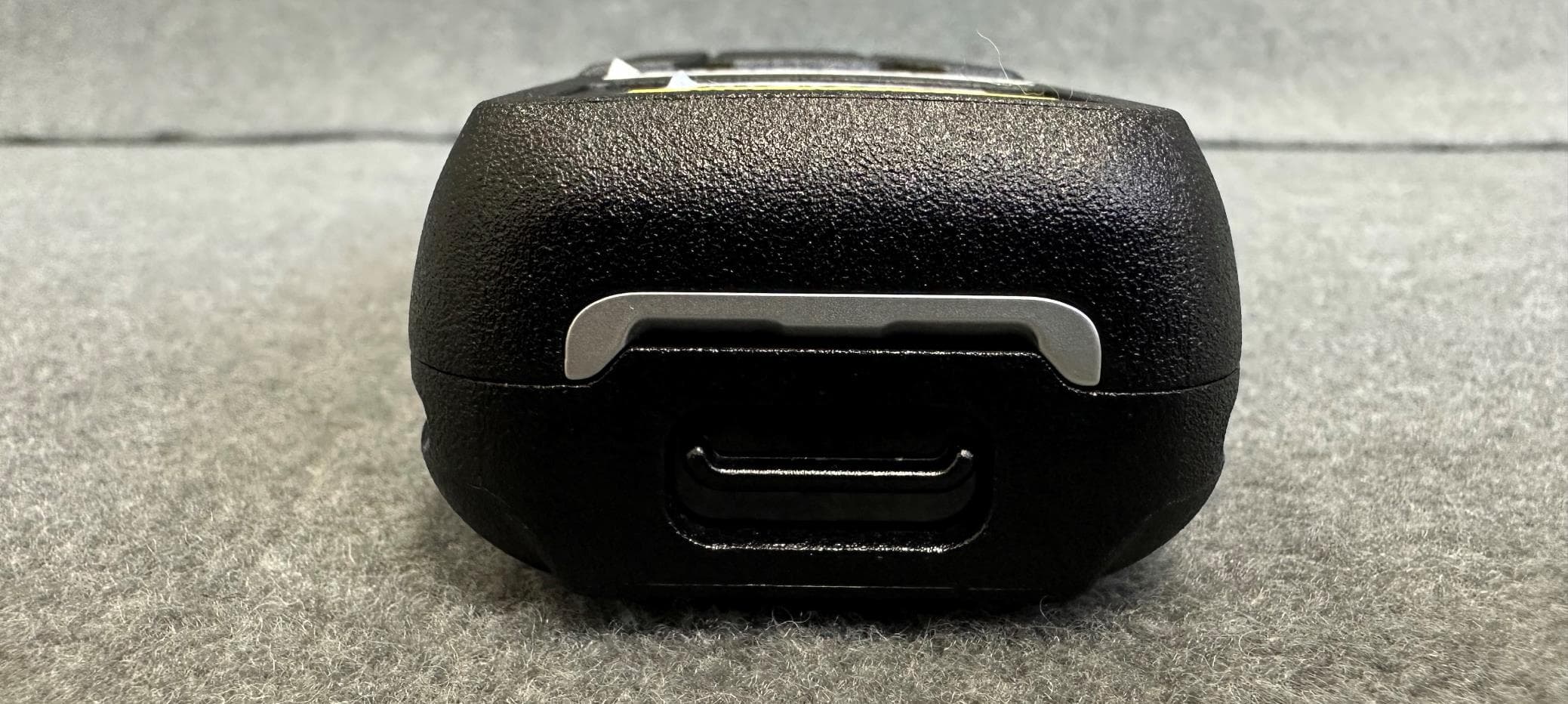
CASTPJHGB
Jan 15, 2026Portable Transceiver
Equipment Class
TNF - Licensed Non-Broadcast Transmitter Held to Face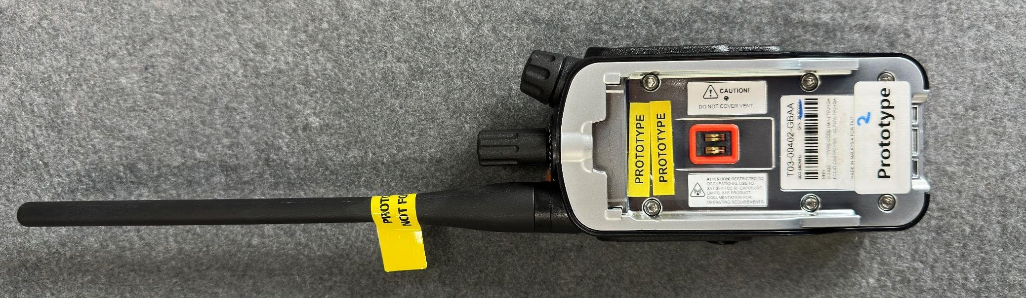
CASTPJHGA
Jan 15, 2026Portable Transceiver
Equipment Class
DSS - Part 15 Spread Spectrum Transmitter