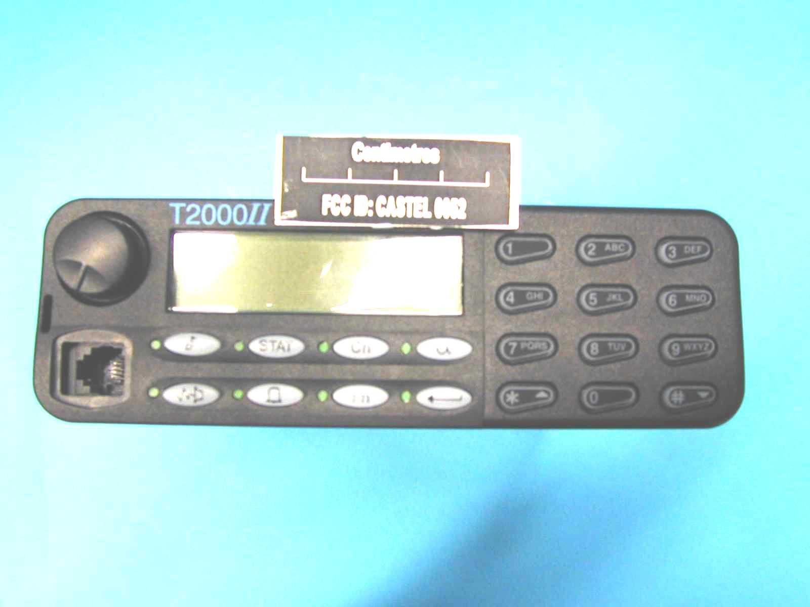
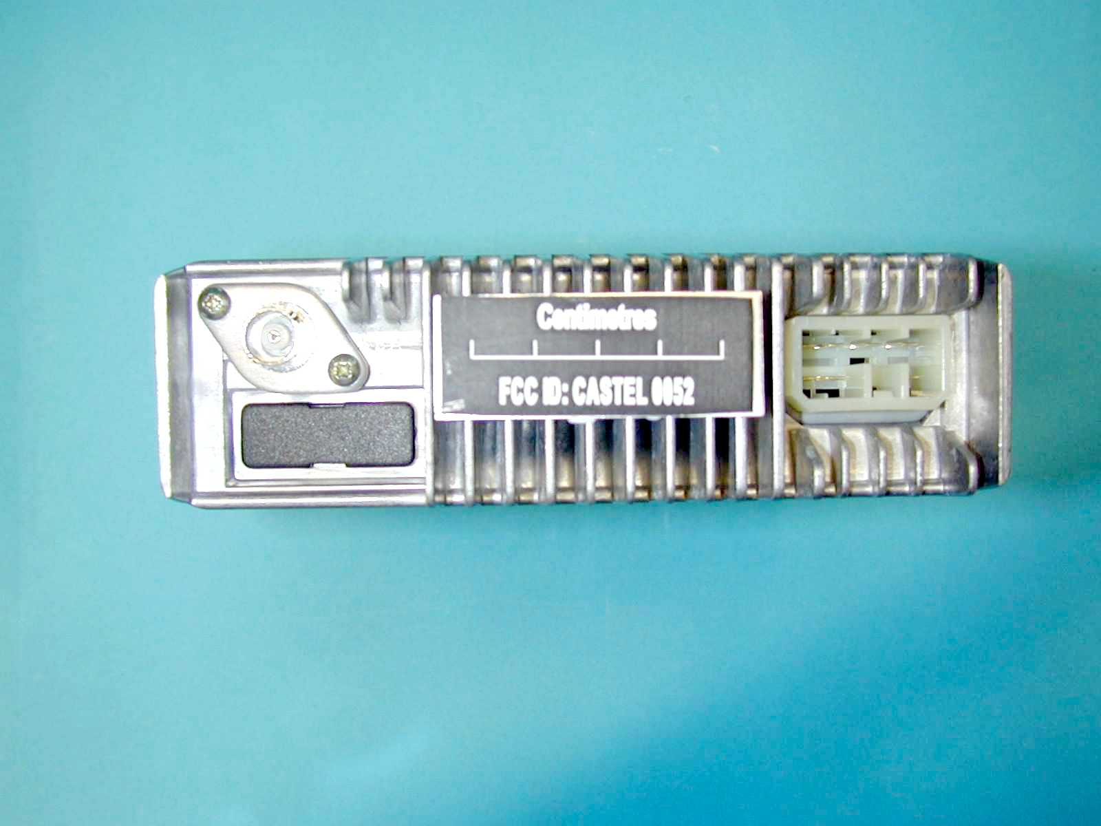
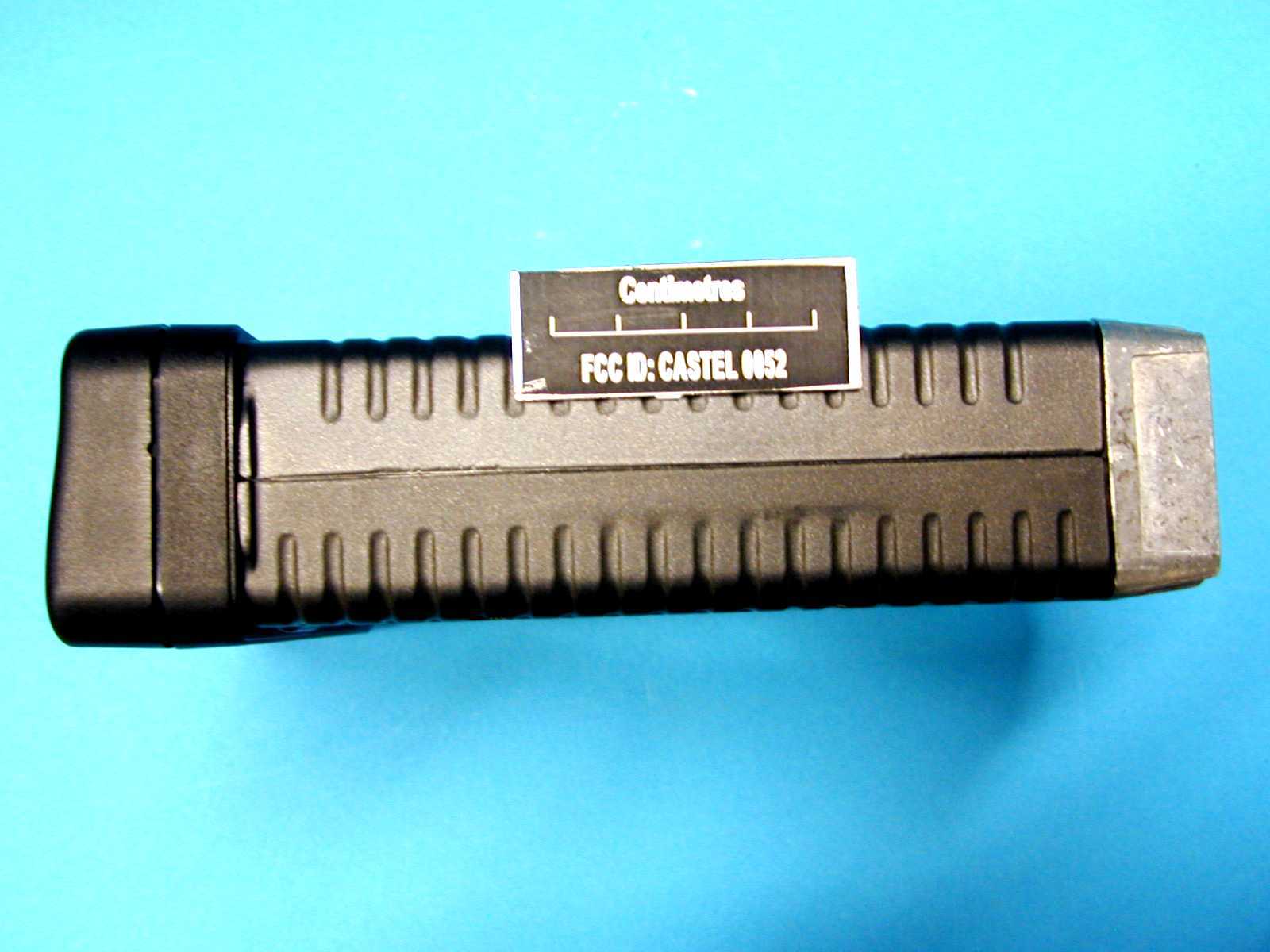
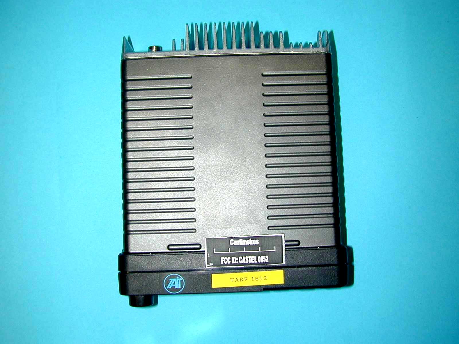
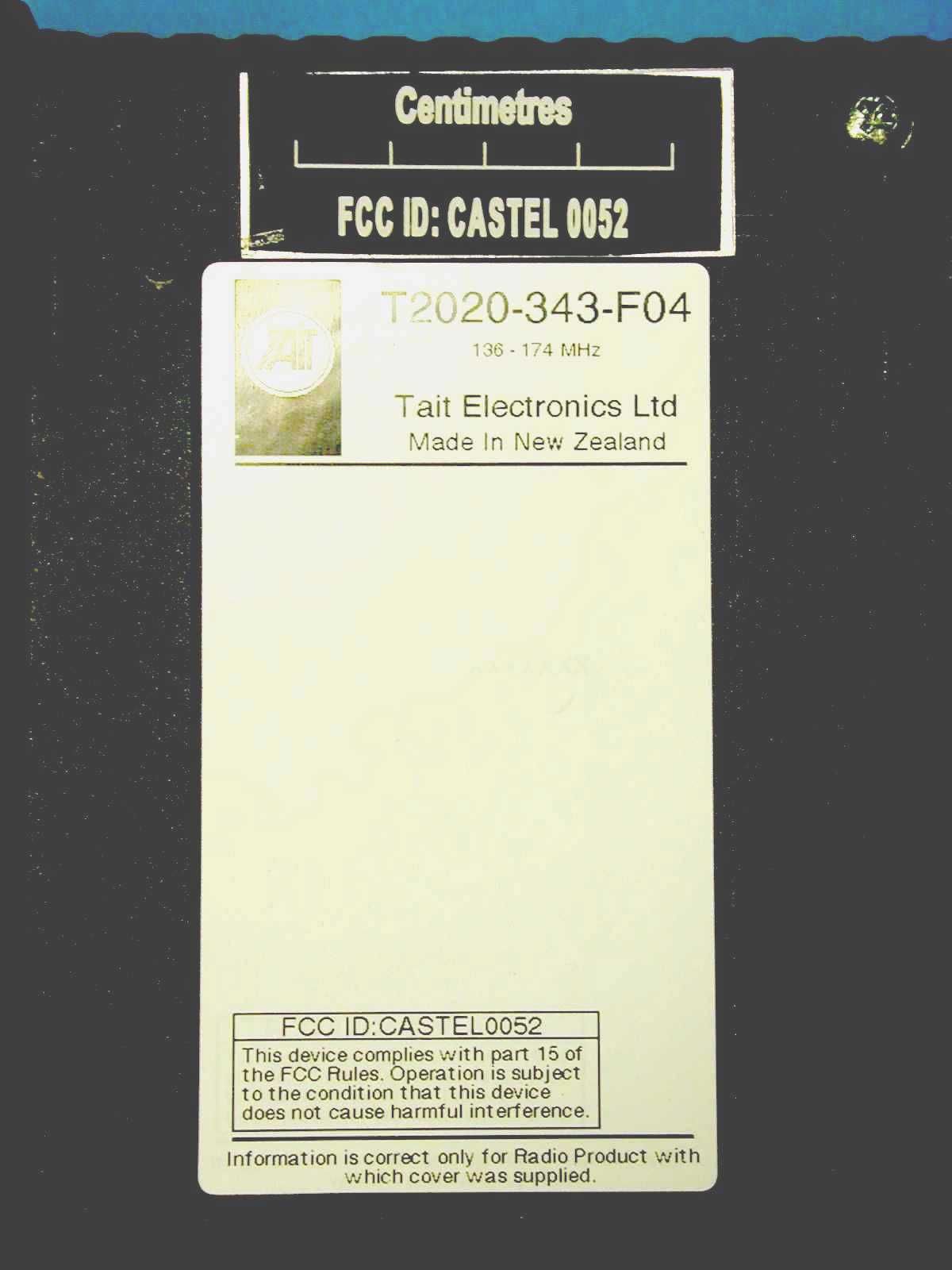
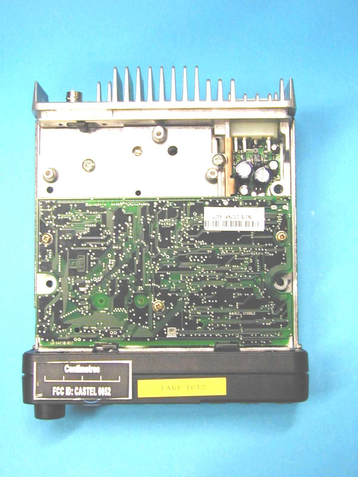
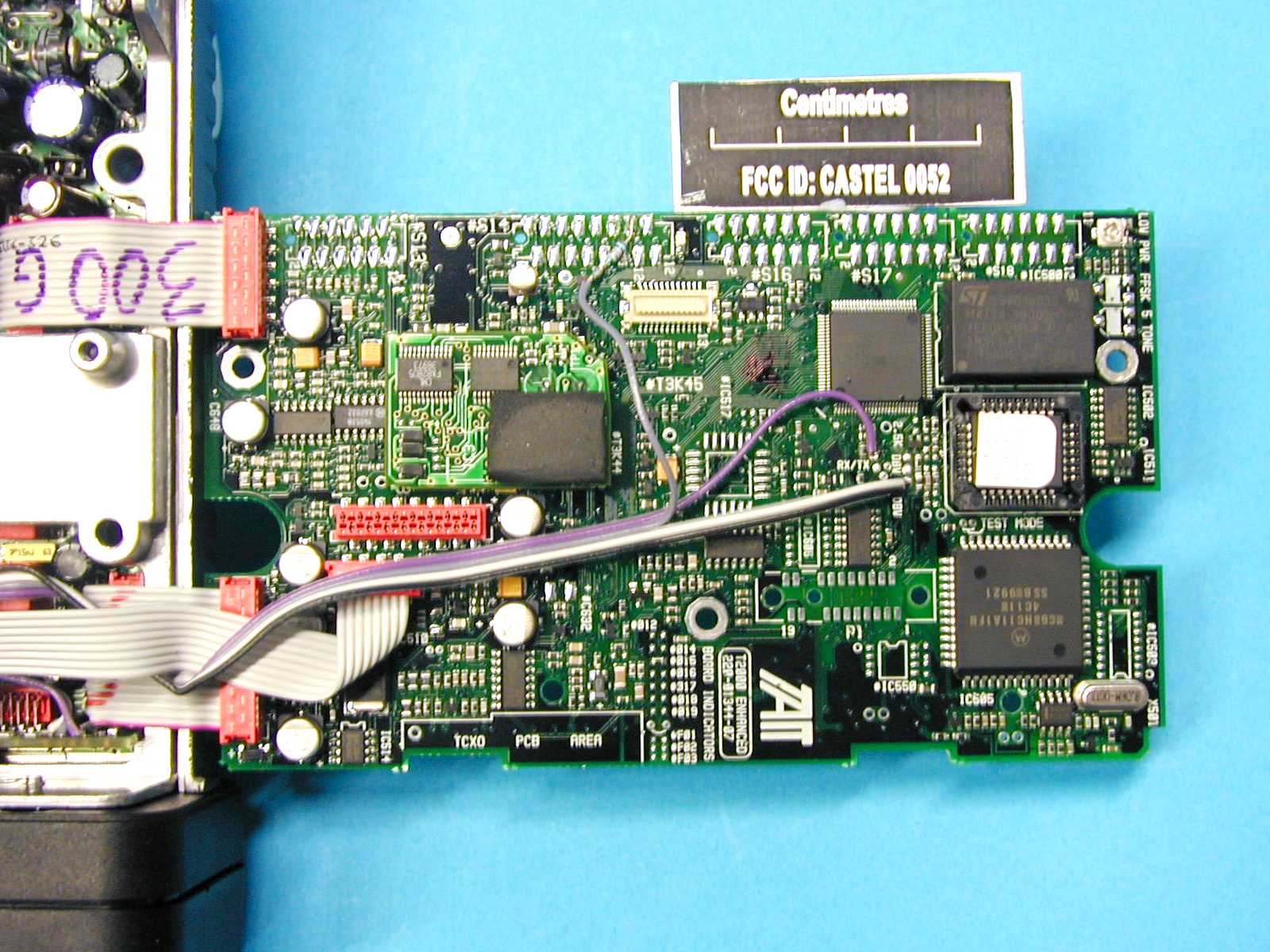
CASTEL0052Mobile Transceiver
Tait International Limited
Click to zoom
Application Details
- Equipment Class
- TNB - Licensed Non-Broadcast Station Transmitter
- Date of Grant
- May 08, 2001
- Application Purpose
- Original Equipment
- Date of Application
- Feb 10, 2001
- Equipment Note
- Mobile Transceiver
- Frequency Range
- 136.00000000 - 174.00000000
- Company
- Tait International Limited
- Country
- New Zealand
Documents & Files
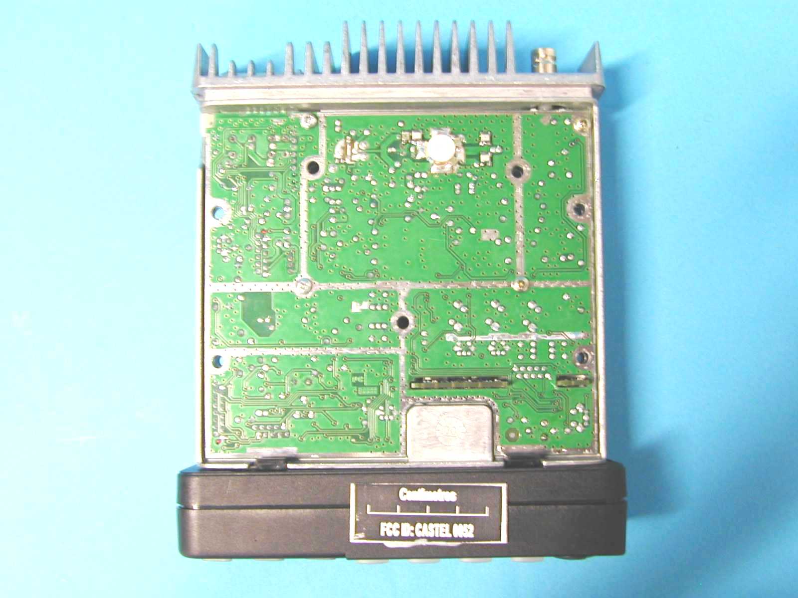
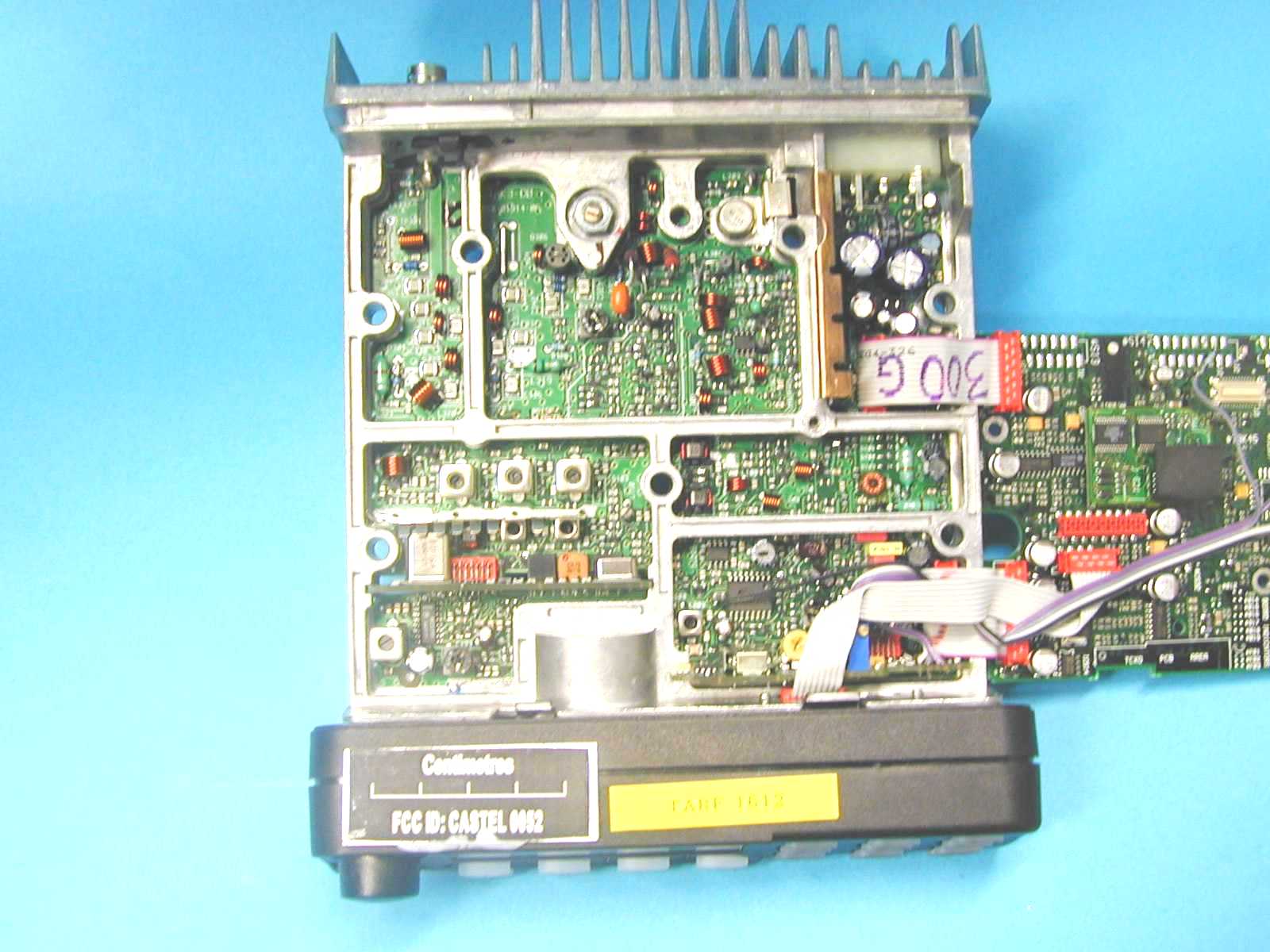
Document Text
Text extracted from the exhibit documents filed with the FCC. Open a document above to read the original.
Users Manual
12T2000 Installation Guide CORPORATE HEAD OFFICE NEW ZEALAND Tait Electronics Ltd P.O. Box 1645, Christchurch Phone : (64) (3) 358-3399 Fax : (64) (3) 358-0340 AUSTRALIA Tait Electronics (Aust) Pty Ltd Phone : (61) (7) 3865-7799 Fax : (61) (7) 3865-7990 Toll Free : (1-300) 304-344 E-mail: [email protected] CANADA Tait Mobile Radio Inc Phone : (1) (905) 472-1100 Fax : (1) (905) 472-5300 Toll Free : (1) 1-800-890-8248 E-mail: [email protected] Tait Latin America Phone : (1) (305) 260-9900 Fax : (1) (305) 260-9209 E-mail: [email protected] NEW ZEALAND Tait Communications Ltd Phone : (64) (3) 348-3301 Fax : (64) (3) 343-0558 E-mail: [email protected] USA Tait Electronics (USA) Inc Phone : (1) (713) 984-8684 Fax : (1) (713) 468-6944 Toll Free : (1-800) 222-1255 E-mail: [email protected] TAIT EUROPE Regional Head Office UNITED KINGDOM Tait Europe Ltd Phone : (44) (1480) 52255 Fax : (44) (1480) 411-996 E-mail: [email protected] FRANCE Tait France S.A.R.L. Phone : (33) (1) 41-14-05-50 Fax : (33) (1) 41-14-05-55 E-mail: [email protected] GERMANY German Office Phone : (49) (911) 2870-7064/7160 Fax : (49) (911) 2870-7077 E-mail: [email protected] TAIT NORTH ASIA Regional Head Office HONG KONG Tait Mobile Radio (Hong Kong) Ltd E-mail: [email protected] Phone : (852) 2369-3040 Fax : (852) 2369-3009 BEIJING Tait Mobile Radio (Hong Kong) Ltd Phone : (86) 10-6510-2680 Fax : (86) 10-6510-2686 E-mail: [email protected] TA I W A N Tait Mobile Radio (Taiwan) Ltd Phone : (886) 2-2731-1290 Fax : (886) 2-2-711-6351 E-mail: [email protected] TAIT SOUTH EAST ASIA Regional Head Office SINGAPORE Tait Electronics (Far East) Pte Ltd Phone : (65) 471-2688 Fax : (65) 479-7778 E-mail: [email protected] THAILAND Tait Mobile Radio Ltd Phone : (662) 267-6290 Fax : (662) 267-6293 E-mail: [email protected] Excellence in Radio Communications T2000 Installation Guide T2000 Installation Guide 2T2000 Installation GuideT2000 Installation Guide11 3. Route the cable as required, fitting grommets where necessary to prevent chafing of the cable insulation. 4. Fit the red connector to the printed circuit board socket – the connector is shaped so that it can be fitted in the correct orientation only. 5. Refit the cable to the cable clamp on the rear cover and slip the two nuts into the receptacles at each end of the rear cover. 6. Refit the rear cover and replace the cover screws, tightening them carefully. Do not overtighten the screws. The control head can now be installed as follows: 1. Mount the bracket for the control panel on a flat surface using the self-tapping screws supplied. 2. Place the control head in the bracket, position it for a good viewing angle, and fit the 2 screws to secure it in place. Microphone Clip The microphone clip must be earthed (to the negative supply line) if hookswitch control of monitor- ing, scanning or call termination is to operate. Refer to the radio’s operating instructions to confirm requirements. Ensure that the microphone clip is mounted in a position where the microphone PTT key cannot be inadvertently activated or jammed on. Installation Checks 1. Plug the microphone into the socket on the lower left-hand corner of the radio’s front 2. Insert the fuses into the power lead. 3. Switch on the radio and confirm that it is operational. 4. Connect an in-line power meter between the radio and the antenna and measure the forward and reflected power levels. Less than 1W should be reflected for 25W forward power. If this is not achieved, check the installation - including antenna length. 5. Make a call to another party on the radio (as described in the operating instructions). Tait Electronics has made every effort to ensure the accuracy of information in this manual. However, Tait Electronics reserves the right to update the radio and/or this manual without notice. 10T2000 Installation Guide Power Cable 1. Disconnect the vehicle’s battery unless specifically prohibited from doing so by the customer, vehicle manufacturer, agent or supplier. In this event, exercise extreme caution throughout the installation and fit the fuses only when the installation is complete. Caution: Always disconnect the radio’s power lead before connecting a second battery or using power from another vehicle (e.g. when “jump-starting” the vehicle). 2. Determine where the battery leads will be routed. 3. Cut the negative and the positive wires where the in-line crimp fuse holders will be placed (as close to the battery as practicable). 4. Insert each end of the negative wire into one of the in-line crimp fuse holders and crimp them to force the metal contacts onto the wires. Terminate the wire at the battery earth. 5. Repeat Step 4 for the positive wire and terminate it at the positive terminal of the battery. Caution: Prevent the power wires chafing on any metal parts. Note: T2000IIradios are designed to operate from a nominal 12V negative earth supply, and require currents of up to 8A. (The radios will tolerate a supply voltage range of 10.8V to 16.0V). In vehicles with a 24V electrical system (e.g. many trucks), it is essential to provide a suitably rated 24/12V converter (e.g. Tait T2007) to isolate the radio from the battery and protect it against excessive voltages. 6. If the economizer is to be controlled by the ignition line, terminate a wire in the power connector and connect the ‘ignition’ wire to a +12V supply which is live only when the vehicle’s ignition is switched ‘On’. External Wire (Horn/Hush/Emergency) The T2000IIcan be configured to operate the vehicle’s horn, radio or a hidden switch: 1. Terminate a suitable length of wiring in the “external” port of the power connector. 2. Run the free end of the external wire from the power connector to the appropriate vehicle wiring. The option’s interface is usually configured to switch or be switched in the ground state. Confirm the exact operation in the documentation supplied with the interface unit. Rem…
Text truncated - open the document above for the full version.
Attestation Statements
TELTEST Laboratories Tait Electronics Ltd PO Box 1645 558 Wairakei Road Christchurch New Zealand Phone: 64 – 3 – 358 3399 Fax: 64 – 3 – 358 0432 12 December 2000 To Whom It May Concern: T2020-343-F04 This equipment meets the requirements of FCC Rules Part 90.203(e) and (g) as applicable. Programming of this product’s transmit frequencies can be performed ONLY by the manufacturer or by service or maintenance personnel. The operator cannot program transmit frequencies using the equipment’s external operation controls. Regards, Sivachanthiran Compliance Laboratory Technician
Cover Letter(s)
TELTEST Laboratories Tait Electronics Ltd PO Box 1645 558 Wairakei Road Christchurch New Zealand Phone:(64) (3) 3583399 Fax:(64) (3) 3580432 12 December 2000 To whom it may concern T2020-343-F04 CONFIDENTIALITY REQUEST Reference rule sections 0.457 (d) (ii) and pursuant to rule section 0.459 (a) confidentiality is requested as follows: Specific Information: Schematics The schematics contain trade secret information which is not made routinely available to the public or to our competitors. Disclosure of this information could result in an unfair advantage to our competitors. It should be treated as confidential for the duration of effectiveness of the Grant Of Authorisation. Regards Sivachanthiran Compliance Laboratory Technician
Operational Description
M2000-001 Copyright TEL31/12/97 T2000 Series II Service Manual Issue 301 March 1998 M2000-00-301 2M2000-00 31/12/97Copyright TEL Head Office New Zealand Tait Electronics Ltd 558 Wairakei Road P.O. Box 1645 Christchurch New Zealand Phone: 64 3 358-3399 Fax: 64 3 358-3636 Australia Tait Electronics (Aust) Pty Ltd 275 Toombul Road Northgate 4013 P.O. Box 679 Virginia Queensland 4014 Australia Phone: 61 7 3865-7799 Toll Free: 1 300 304-344 Fax: 61 7 3865-7990 E-mail: [email protected] Canada Ta i t M o b i l e R a d i o I n c . Unit 5, 158 Anderson Avenue Markham Ontario L6E1A9 Canada Phone: 1 905 472-1100 Fax: 1 905 472-5300 E-mail: [email protected] France Ta i t F r a n c e S . A . R . L . 2 avenue de la Cristallerie 92 316 Sèvres, Cedex France Phone: 33 1 41 14-05-50 Fax: 33 1 41 14-05-55 E-mail: [email protected] Germany Tait Mobilfunk GmbH Willstätterstraße 50 D-90449 Nürnberg 60 Germany Phone: 49 911 967-460 Fax: 49 911 967-4679 E-mail: [email protected] Hong Kong Tait Mobile Radio (Hong Kong) Ltd Room 703A New East Ocean Centre 9 Science Museum Road Ts i m S h a Ts u i E a s t Hong Kong Phone: 852 2369-3040 Fax: 852 2369-3009 E-mail: [email protected] New Zealand Tait Communications Ltd Unit 4, 75 Blenheim Road P.O. Box 1185 Christchurch Phone: 64 3 348-3301 Fax: 64 3 343-0558 E-mail: [email protected] Singapore Tait Electronics (Far East) Pte Ltd 4 Leng Kee Road SIS Building #05-11A Singapore 159088 Phone: 65 471-2688 Fax: 65 479-7778 E-mail: [email protected] Taiwan Tait Mobile Radio (Taiwan) Ltd 1104, 142 Chung Hsiao E Rd Sec 4 Ta i p e i Ta i w a n Phone: 886 2 2731-1290 Fax: 886 2 2711-6351 E-mail: [email protected] Thailand Tait Mobile Radio Ltd 14/1 Suwan Tower, Ground Floor Soi Saladaeng 1 North Sathorn Rd Bangrak Bangkok 10500 Thailand Phone: 662 267-6290 Fax: 662 267-6293 E-mail: [email protected] United Kingdom Tait Mobile Radio Ltd Ermine Business Park Ermine Road Huntingdon Cambridgeshire PE18 6YA United Kingdom Phone: 44 1480-52255 Fax: 44 1480-411996 E-mail: [email protected] USA Tait Electronics (USA) Inc. 9434 Old Katy Road Suite 110 Houston Texas 77055 USA Phone: 1 713 984-8684 Toll Free: 1 800 222-1255 Fax: 1 713 468-6944 E-mail: [email protected] M2000-003 Copyright TEL31/11/96 About This Manual Scope This manual contains general, technical and servicing informa- tion on T2000 Series II mobile two-way radios. Format We have published this manual in a ring binder so that “revision packages” containing additional information can be added as required. Revision Packages Revision packages will normally be published to coincide with the release of information on a new PCB, and may also contain additions or corrections pertaining to other parts of the manual. If you return the customer registration card at the front of this manual, you will be notified when revision packages containing new PCB information and/or text are available. You may then order as many packages as you require from your local Tait Company. Revision packages are supplied ready-punched for inclusion in your manual. Revision Control Each page in this manual has a date of issue. This is to comply with various Quality Standards, but will also serve to identify which pages have been updated and when. Each page and its publication date is listed in the “List of Effective Pages”, and a new list containing any new/revised pages and their publica- tion dates will be sent with each revision package. Any portion of text that has been changed is marked by a verti- cal line (as shown at left) in the outer margin of the page. Where the removal of an entire paragraph means there is no text left to mark, an arrow (as shown at left) will appear in the outer mar- gin. The number beside the arrow will indicate how many para- graphs have been deleted. The manual issue and revision status are indicated by the last three digits of the manual product code. These digits start at 100 and will increment through 101, 102, 103, etc., as revision pack- ages are published, e.g: Thus, Issue 301 indicates the first revision to issue 3, and means that one package should have been added to the manual. The issue digit will only change if there is a major product revision, or if the number of revision packages to be included means that the manual becomes difficult to use, at which point a new issue manual will be published in a new ring binder. PCB Information PCB information is provided for all current issue PCBs, as well as all previous issue PCBs manufactured in production quanti- ties, and is grouped according to PCB. Thus, you will find the parts list, grid reference index (if necessary), PCB layouts and circuit diagram(s) for each individual PCB grouped together. 2 3 0 1 issue statusrevision status 4M2000-00 31/11/96Copyright TEL Errors If you find an error in this manual, or have a suggestion on how it might be improved, please do not hesitate to contact the Tech- nical Writer, Product Support Group, Tait Mobile Radio Divi- sion, Tait Electronics Ltd, P.O. Box 1645, Christchurch, New Zealand. Technical Information Any enquiries regarding this manual or the equipment it describes should be addressed in the first instance to your nearest approved Tait Dealer or Service Centre. Further tech- nical assistance may be obtained from the Product Support Group, Tait Mobile Radio Division, Tait Electronics Ltd, Christchurch, New Zealand. Updating Equipment And Manuals In the interests of improving performance, reliability or servicing, Tait Electronics Ltd reserve the right to update their equipment and/or manuals without prior notice. Copyright All information contained in this manual is the property of Tait Electronics Ltd. All rights are reserved. This manual may not, in whole or part, be copied, photocopied, reproduced, translated stored or reduced to any electronic medium or machine readable form without prior written permission from Tait Electronics Ltd. Ordering Tait Service Manuals Servi…
Text truncated - open the document above for the full version.
Operational Description
M2000-00Introduction To Servicing3.1 Copyright TEL30/12/97 "8]ca^SdRcX^]ÒC^ÒBTaeXRX]VÒ This Section provides information necessary for servicing T2000 Series II radios, and covers the following topics: SectionTitlePage 3.1Servicing Precautions3.2 3.1.1 3.1.2 3.1.3 3.1.4 3.1.5 Caution: Accidental Transmit Caution: Antenna Loading Caution: Beryllium Oxide & Power Transistors Caution: CMOS Devices Caution: Screw Head Types 3.2 3.2 3.2 3.2 3.3 3.2Disassembly Instructions3.5 3.2.1 3.2.2 3.2.3 3.2.3.1 3.2.3.2 3.2.4 3.2.4.1 3.2.4.2 3.2.5 3.2.6 To G a i n A c c e s s To T h e L o g i c P C B To Remove The Bottom Cover And Microprocessor Shield To D e t a c h T h e C o n t r o l H e a d Locally Mounted Models Remotely Mounted Models To Disassemble The Control Head T2010, T2015, T203X & T2060 Radios T2020, T2040 & T2050 Radios To Detach The EMC Filter PCB To Remote A Locally Mounted T2020, T2040 & T2050 3.5 3.5 3.6 3.6 3.6 3.7 3.7 3.9 3.11 3.11 3.3Power Amplifier - Special Instructions3.12 3.3.1 3.3.2 To R e p l a c e PA Tr a n s i s t o r s To Remove Case Mica Capacitors 3.12 3.12 3.4Repair3.13 3.4.1 3.4.1.1 3.4.1.2 3.4.1.3 3.4.1.4 3.4.2 3.4.2.1 3.4.2.2 Surface Mount Devices Surface Mount Device (SMD) Precautions Servicing Equipment Required Removal & Replacement Of SMD Components Common Causes Of SMD Failure Leaded Component Removal Desoldering Iron Method Component Cutting Method 3.13 3.13 3.13 3.15 3.17 3.17 3.17 3.18 3.5Programming3.18 3.2Introduction To ServicingM2000-00 31/10/96Copyright TEL 3.1Servicing Precautions 3.1.1Caution: Accidental Transmit Under certain circumstances the microprocessor can key the transmitter. Ensure that all instruments are protected from accidental transmit at all times. 3.1.2Caution: Antenna Loading The equipment has been designed to operate with a 50Ω termination impedance, but will tolerate a wide range of antenna loading conditions. However, it is strongly recom- mended that the transmitter is not operated in the absence of a suitable load. Failure to observe this precaution may result in damage to the transmitter power output stage. 3.1.3Caution: Beryllium Oxide & Power Transistors The RF power transistors in the T2000 all contain some beryllium oxide. This substance, while perfectly harmless in its normal solid form, can become a severe health hazard when it has been reduced to dust. For this reason the RF power transistors should not be scratched, mutilated, filed, machined, or physically damaged in any way that can produce dust particles. 3.1.4Caution: CMOS Devices This equipment contains CMOS Devices which are susceptible to damage from static charges. Care when handling these devices is essential. For correct handling procedures refer to manufacturers’ data books covering CMOS devices, e.g. Philips Data Handbook Covering CMOS Devices; Motorola CMOS Data Book Section 5 (Handling Procedures), etc. The following diagram shows a typical anti-static bench set-up. Figure 3.1 Anti-Static Bench Set-Up to building earth (not mains earth) via 1M series resistor metal frame conductive wrist strap conductive rubber bench mat M2000-00Introduction To Servicing3.3 Copyright TEL31/10/96 3.1.5Caution: Screw Head Types Pozidriv screws are the preferred standard on all T2000 series equipment. Pozidriv No. 1 and 2 screwdrivers will fit all pozidriv screws used in the T2000: Philips cross-head screwdrivers are not satisfactory for use on these screws. The following diagram identifies the differences between Philips and Pozidriv screw- drivers. Figure 3.2 Screwdriver Identification The diagrams on the following pages show the types of screws used in the T2000 Series II radios, their locations and torque specifications. driving flutes with parallel sides driving flutes with tapered sides PozidrivPhilips internal notches "star" markings between slots no special markings slots with parallel sides slots with tapered sides ridges between driving flutes 3.4Introduction To ServicingM2000-00 31/10/96Copyright TEL Figure 3.3 T2000 Series II Radio Assembly ItemDescriptionIPNQuantityTorque (in.lb) 1TOP COVER303-23134-011 2LOGIC PCBSEE PARTS LIST1 3SCREW M3X8 PANPOZI TAPTITE (LOGIC PCB SCREWS)349-00020-3238 4MACHINE SCREW M4X25 (MICRO. SHIELD SCREWS)345-00050-18312 5MICROPROCESSOR SHIELD319-01164-XX1 6CHASSIS308-13093-XX1 7D-RANGE BLANKING PLATE360-01053-XX1 8SCREW M3X8 PANPOZI TAPTITE (RF CONNECTOR SCREWS)349-00020-3228 9RF CONNECTOR PLATE SEE PARTS LIST (SECTION 7) 1 10RF CONNECTOR1 11RF PCB1 12SCREW M3X8 PANPOZI TAPTITE (RF PCB SCREWS)349-00020-3248 13BOTTOM COVER303-23135-XX1 14M4X35 PANPOZI TAPTITE (BOTTOM COVER SCREWS)349-00020-49412 7 13 14 9 12 11 6 1 2 3 3 4 4 5 8 10 14 12 M2000-00Introduction To Servicing3.5 Copyright TEL31/10/96 3.2Disassembly Instructions Caution:To carry out alignment it is necessary to remove only the top cover (1) and logic PCB retaining screws (3). It is essential that the bottom cover (13) and microprocessor shield (5) with its three retaining screws (4) are torqued down as specified in Figure 3.3. Caution:Various electronic components within the radio can be damaged by elec- trostatic discharge. A properly grounded earth mat and wrist strap should be used at all times (refer to Section 3.1.4). 3.2.1To Gain Access To The Logic PCB Refer to Figure 3.3. Remove the top cover (1) by unscrewing the four bottom cover screws (14). Remove the three logic PCB retaining screws (3). It should now be possible to open out the logic PCB (2), giving access to both sides of the logic PCB, and access to the RF PCB (11) tuning points, audio, plug-in TCXO PCB and loop filter components. 3.2.2To Remove The Bottom Cover And Microprocessor Shield Refer to Figure 3.3. Remove the top cover and logic PCB screws as instructed in Section 3.2.1, then remove the three microprocessor shield retaining screws (4). Remove the screw securing the earthing wire from the control head to the micro- processor shield. It should now be possible to lift off the microprocessor shield (5) and th…
Text truncated - open the document above for the full version.
Operational Description
M2000-00 PCB Information7.1 Copyright TEL31/10/00 7PCB Information This Section provides parts lists, circuit diagrams and component location information on the individual PCBs within the T2000 Series II radio. The following PCBs are covered within this Section: SectionTitlePage Frequency (MHz) 7.1T2000-100 RF PCBIPN 220-01331-027.1.1220 to 270 7.2T2000-200 RF PCBIPN 220-01202-107.2.166 to 88 7.3 T2000-300 RF PCBIPN 220-01314-01 IPN 220-01314-05 7.3.1 7.3.11 136 to 174 7.4T2000-400 RF PCBIPN 220-01204-117.4.1175 to 225 7.5T2000-500/-600 RF PCBIPN 220-01205-14 IPN 220-01205-19 7.5.1 7.5.13 400 to 530 7.6 T2000-700/-900 RF PCBIPN 220-01289-01 IPN 220-01389-03 7.6.1 7.6.11 330 to 400 7.7T2000-800 RF PCBIPN 220-01305-037.7.1800 to 870 7.8T2000 IF PCBIPN 220-01565-047.8.1 7.9T2000 TCXO /Tx Audio PCBIPN 220-01657-017.9.1 7.10T2010 & T2015 HC05 Logic PCBIPN 220-01377-01 IPN 220-01377-02 IPN 220-01377-03 7.10.1 7.10.11 7.10.23 7.11T2020, T203X, T2040, T2050 & T2060 HC11 Logic PCB IPN 220-01344-02 IPN 220-01344-04 IPN 220-01344-07 7.11.1 7.11.13 7.11.25 7.12T2010/T2030 Control Head PCBIPN 220-01319-017.12.1 7.13T2015/T2060 Control Head PCBIPN 220-01320-017.13.1 7.14T2020/40 /50 Control Head PCBIPN 220-01321-047.14.1 7.15T2035 Control Head PCBIPN 220-01322-037.15.1 7.16T2000 EMC Filter PCBIPN 220-01383-017.16.1 7.17T2000 Data Interface Decoupling PCB IPN 220-01388-017.17.1 7.2PCB Information M2000-00 31/11/96Copyright TEL PCB Identification All PCBs are identified by a unique 10 digit ‘internal part number’ (IPN), e.g. 220-01330-02, which is screen printed onto the PCB (usually the top side). The last 2 digits of this number define the issue status, which starts at 00 and increments through 01, 02, 03, etc. as the PCB is updated. Some issue PCBs never reach full produc- tion status, and are therefore not included in this manual. A letter following the 10 digit IPN has no relevance in identifying the PCB for service purposes. In the following diagram of the T2000-66 UART PCB, the IPN is 220-01348-03, (i.e. issue 03 of the PCB). It is important that you identify which issue PCB you are working on so that you can refer to the appropriate PCB information. M2000-00 PCB Information7.3 Copyright TEL31/11/96 Parts Lists The 10 digit numbers (000-00000-00) in the parts lists are ‘internal part numbers’ (IPNs). Your spare parts orders can be handled more efficiently if you quote the IPN and pro- vide a brief description of the part. The components listed in the parts lists are divided into two main types: those with a circuit reference (e.g. C201, D106, R121, etc.) and those without (mechanical and miscel- laneous). Those with a circuit reference are grouped in alphabetical order and then in numerical order within each group. Each component entry comprises three or four columns, as shown below. The mechanical and miscellaneous section lists the variant and common parts in IPN order. Variant Parts A variant component is one that has the same circuit reference but different value or specification in different product types, models or options. Variant components are indi- cated by a character prefix, such as ‘&’, ‘#’ or ‘=’. circuit reference - lists component in numerical order variant column - indicates that the component is only fitted to this particular model, type or option Internal Part Number - order the component b y this number description - gives a brief description of the component 7.4PCB Information M2000-00 31/11/96Copyright TEL Locating Components Grid Reference Indexes To assist in locating components and labelled pads on the PCB layouts and circuit dia- grams, a component grid reference index has been provided. This index lists the compo- nents and pads in alphabetical order, along with the appropriate alphanumeric grid references, as shown below. Using Circuit Diagrams Reading a circuit diagram is similar to reading a road map, in that both have an alpha- numeric border. The circuit diagrams in this manual use letters to represent the horizon- tal axis, and numbers for the vertical axis. These circuit diagram ‘grid references’ are useful in following a circuit that is spread over two or more sheets. When a line representing part of the circuitry is discontinued, a reference will be given at the end of the line to indicate where the rest of the circuitry is located. The first digit refers to the sheet number (printed on the bottom right hand corner of the circuit dia- gram) and the last two characters refer to the location on that sheet of the continuation of the circuit (e.g. 1-D4). If more than one line is represented (indicated by a double thickness line), a dot with a reference label will follow the route each individual line represents. circuit diagram reference P CB layout reference components listed in numerical order layer number: 1 = top side layer 2 = bottom layer (2 layer PCB) component location on the layer sheet name or number e.g. PA = Power Amplifier component location on the sheet M2000-00T2000-100 RF PCB7.1.1 Copyright TEL31/10/96 RefVarIPNDescriptionRefVarIPNDescription IPN 220-01331-02 2*6WAY240-00020-51PLUG 12 WAY 2*6 FLAT CABLE TERMN C1015-23680-08CAP CER 0805 CHIP 680P 10% X7R 50V C2015-23680-08CAP CER 0805 CHIP 680P 10% X7R 50V C3015-23680-08CAP CER 0805 CHIP 680P 10% X7R 50V C100015-25100-08CAP CER 0805 CHIP 10N 10% X7R 50V C101015-21820-01CAP CER 0805 CHIP 8P2 +/-0.25P NPO 50V C102015-22680-01CAP CER 0805 CHIP 68P 5% NPO 50V C103015-22120-01CAP CER 0805 CHIP 12P 5% NPO 50V C104015-06100-08CAP CER 1206 CHIP 100N 10% X7R 50V C105015-21120-01CAP CER 0805 CHIP 1P2 +/-0.25 NPO 50V C106015-23680-08CAP CER 0805 CHIP 680P 10% X7R 50V C107015-21560-01CAP CER 0805 CHIP 5P6 +/-0.25P NPO 50V C108015-25100-08CAP CER 0805 CHIP 10N 10% X7R 50V C109015-21220-01CAP CER 0805 CHIP 2P2 +/-0.25P NPO 50V C110015-23680-08CAP CER 0805 CHIP 680P 10% X7R 50V C111015-21820-01CAP CER 0805 CHIP 8P2 +/-0.25P NPO 50V C112015-21180-01CAP CER 0805 CHIP 1P8 +/-0.25 NPO 50V C113015-21220-01CAP CER 0805 C…
Text truncated - open the document above for the full version.
Operational Description
M2000-00T2000-300 RF PCB7.3.1 Copyright TEL31/10/96 RefVarIPNDescriptionRefVarIPNDescription IPN 220-01314-01 C1015-24100-08CAP CER 0805 CHIP 1N 10% X7R 50V C2015-24100-08CAP CER 0805 CHIP 1N 10% X7R 50V C3015-24100-08CAP CER 0805 CHIP 1N 10% X7R 50V C100015-25100-08CAP CER 0805 CHIP 10N 10% X7R 50V C102015-22470-01CAP CER 0805 CHIP 47P 5% NPO 50V C103015-22220-01CAP CER 0805 CHIP 22P 5% NPO 50V C104015-06100-08CAP CER 1206 CHIP 100N 10% X7R 50V C105015-21180-01CAP CER 0805 CHIP 1P8 +/-0.25 NPO 50V C106015-23680-08CAP CER 0805 CHIP 680P 10% X7R 50V C107015-22330-01CAP CER 0805 CHIP 33P 5% NPO 50V C108015-25100-08CAP CER 0805 CHIP 10N 10% X7R 50V C109015-21820-01CAP CER 0805 CHIP 8P2 +/-0.25P NPO 50V C110015-23120-01CAP CER 0805 CHIP 120P 5% NPO 50V C111015-23680-08CAP CER 0805 CHIP 680P 10% X7R 50V C112015-22100-01CAP CER 0805 CHIP 10P +/-0.5P NPO 50V C113015-23120-01CAP CER 0805 CHIP 120P 5% NPO 50V C114015-23680-08CAP CER 0805 CHIP 680P 10% X7R 50V C115015-21820-01CAP CER 0805 CHIP 8P2 +/-0.25P NPO 50V C116015-23680-08CAP CER 0805 CHIP 680P 10% X7R 50V C121015-22330-01CAP CER 0805 CHIP 33P 5% NPO 50V C122015-23680-08CAP CER 0805 CHIP 680P 10% X7R 50V C123015-25100-08CAP CER 0805 CHIP 10N 10% X7R 50V C124015-22220-01CAP CER 0805 CHIP 22P 5% NPO 50V C125015-21680-01CAP CER 0805 CHIP 6P8 +/-0.25P NPO 50V C126015-22220-01CAP CER 0805 CHIP 22P 5% NPO 50V C127015-22560-01CAP CER 0805 CHIP 56P 5% NPO 50V C128015-22330-01CAP CER 0805 CHIP 33P 5% NPO 50V C129015-25100-08CAP CER 0805 CHIP 10N 10% X7R 50V C130015-25100-08CAP CER 0805 CHIP 10N 10% X7R 50V C133015-23270-01CAP CER 0805 CHIP 270P 5% NPO 50V C134015-22100-01CAP CER 0805 CHIP 10P +/-0.5P NPO 50V C135015-23150-01CAP CER 0805 CHIP 150P 5% NPO 50V C136015-22270-01CAP CER 0805 CHIP 27P 5% NPO 50V C137015-23680-08CAP CER 0805 CHIP 680P 10% X7R 50V C138015-22270-01CAP CER 0805 CHIP 27P 5% NPO 50V C140015-22100-01CAP CER 0805 CHIP 10P +/-0.5P NPO 50V C141015-23270-01CAP CER 0805 CHIP 270P 5% NPO 50V C142015-22330-01CAP CER 0805 CHIP 33P 5% NPO 50V C145015-23100-01CAP CER 0805 CHIP 100P 5% NPO 50V C147015-25100-08CAP CER 0805 CHIP 10N 10% X7R 50V C148015-22180-01CAP CER 0805 CHIP 18P 5% NPO 50V C149015-25100-08CAP CER 0805 CHIP 10N 10% X7R 50V C150015-23100-01CAP CER 0805 CHIP 100P 5% NPO 50V C151015-06100-08CAP CER 1206 CHIP 100N 10% X7R 50V C152015-23100-01CAP CER 0805 CHIP 100P 5% NPO 50V C152A015-25100-08CAP CER 0805 CHIP 10N 10% X7R 50V C153020-57470-10CAP ELECT AI RDL 4U7 50V LO ESR C153A015-23100-01CAP CER 0805 CHIP 100P 5% NPO 50V C154015-25100-08CAP CER 0805 CHIP 10N 10% X7R 50V C155015-23100-01CAP CER 0805 CHIP 100P 5% NPO 50V C157015-06100-08CAP CER 1206 CHIP 100N 10% X7R 50V C158015-24100-08CAP CER 0805 CHIP 1N 10% X7R 50V C160015-23270-01CAP CER 0805 CHIP 270P 5% NPO 50V C174020-58470-05CAP ELECT AI RDL 47M 16V 6.3X7MM C175015-06100-08CAP CER 1206 CHIP 100N 10% X7R 50V C176015-06100-08CAP CER 1206 CHIP 100N 10% X7R 50V C179015-25100-08CAP CER 0805 CHIP 10N 10% X7R 50V C180015-06100-08CAP CER 1206 CHIP 100N 10% X7R 50V C181015-06100-08CAP CER 1206 CHIP 100N 10% X7R 50V C185015-25100-08CAP CER 0805 CHIP 10N 10% X7R 50V C186015-25100-08CAP CER 0805 CHIP 10N 10% X7R 50V C187015-24100-08CAP CER 0805 CHIP 1N 10% X7R 50V C188015-23100-01CAP CER 0805 CHIP 100P 5% NPO 50V *C189015-23470-08CAP CER 0805 CHIP 470P 10% X7R 50V *C190015-23470-08CAP CER 0805 CHIP 470P 10% X7R 50V C191015-24100-08CAP CER 0805 CHIP 1N 10% X7R 50V C192015-22330-01CAP CER 0805 CHIP 33P 5% NPO 50V C193020-57470-10CAP ELECT AI RDL 4U7 50V LO ESR C194015-23680-08CAP CER 0805 CHIP 680P 10% X7R 50V C195015-23680-08CAP CER 0805 CHIP 680P 10% X7R 50V C196015-06100-08CAP CER 1206 CHIP 100N 10% X7R 50V C197015-06100-08CAP CER 1206 CHIP 100N 10% X7R 50V C198015-23220-01CAP CER 0805 CHIP 220P 5% NPO 50V C199015-24100-08CAP CER 0805 CHIP 1N 10% X7R 50V C200015-25100-08CAP CER 0805 CHIP 10N 10% X7R 50V C205015-23680-08CAP CER 0805 CHIP 680P 10% X7R 50V C206015-06100-08CAP CER 1206 CHIP 100N 10% X7R 50V C207015-25100-08CAP CER 0805 CHIP 10N 10% X7R 50V C208015-25100-08CAP CER 0805 CHIP 10N 10% X7R 50V C209015-25100-08CAP CER 0805 CHIP 10N 10% X7R 50V C210015-25100-08CAP CER 0805 CHIP 10N 10% X7R 50V C211015-23150-01CAP CER 0805 CHIP 150P 5% NPO 50V C212015-21390-01CAP CER 0805 CHIP 3P9 +/-0.25P NPO 50V C213020-58470-05CAP ELECT AI RDL 47M 16V 6.3X7MM C214015-23680-08CAP CER 0805 CHIP 680P 10% X7R 50V C215020-57470-10CAP ELECT AI RDL 4U7 50V LO ESR C216015-25100-08CAP CER 0805 CHIP 10N 10% X7R 50V C217020-58470-05CAP ELECT AI RDL 47M 16V 6.3X7MM C218020-57470-10CAP ELECT AI RDL 4U7 50V LO ESR C219020-57470-10CAP ELECT AI RDL 4U7 50V LO ESR C220022-55150-10CAP MYLAR AI 15N 5% 63V POTTED C221…
Text truncated - open the document above for the full version.
Contact Information
Applicant
Linda White(Standards and Regulatory Manager)
Technical Contact
Tait Electronics LtdStephen A Crompton
[email protected]64-3-3586635
558 Wairakei Road · Christchurch · New Zealand
Non-Technical Contact
Tait Electronics LtdStephen A Crompton
[email protected]64-3-3586635
Technical Specifications
| # | Rule Parts | Frequency Range | Power Output | Emission | Tolerance |
|---|---|---|---|---|---|
| 4 | 22,9 | 136 MHz - 174 MHz | 5 W | 16K0F3E | 5 ppm |
Other Applications from Tait International Limited
CASTBCHGB
May 12, 2026Base Station Transceiver
Equipment Class
TNB - Licensed Non-Broadcast Station Transmitter
CASTBCHGA
May 12, 2026Base Station Transceiver
Equipment Class
TNB - Licensed Non-Broadcast Station Transmitter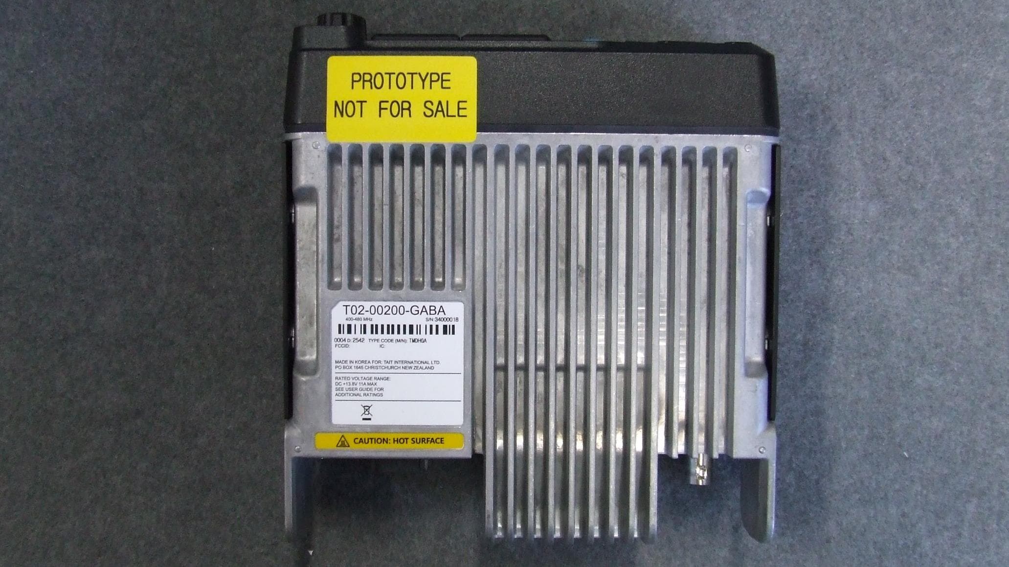
CASTMDHGA
Feb 04, 2026Mobile Transceiver
Equipment Class
TNB - Licensed Non-Broadcast Station Transmitter
CASTPJHGB
Jan 15, 2026Portable Transceiver
Equipment Class
TNF - Licensed Non-Broadcast Transmitter Held to Face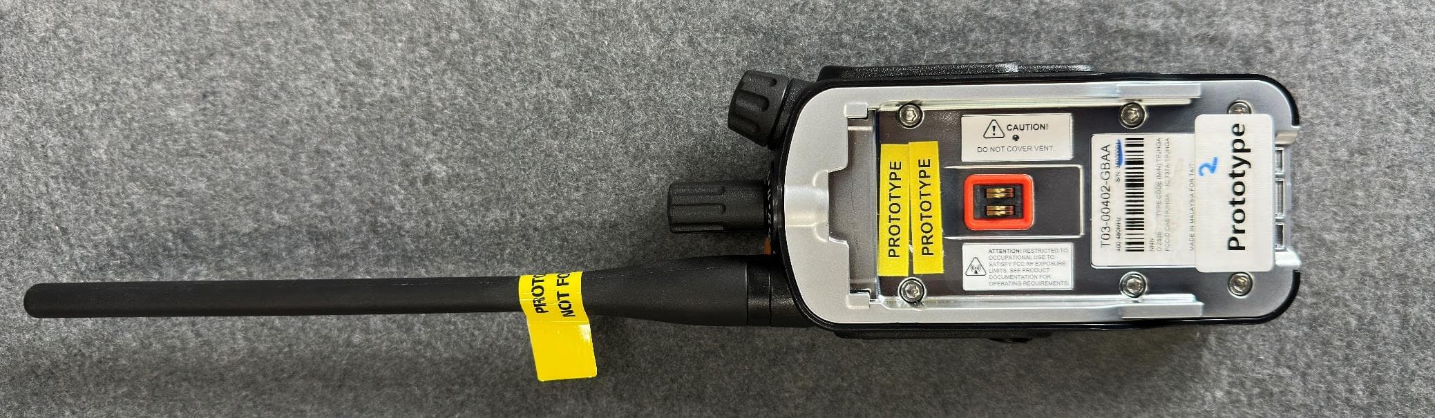
CASTPJHGA
Jan 15, 2026Portable Transceiver
Equipment Class
DSS - Part 15 Spread Spectrum Transmitter