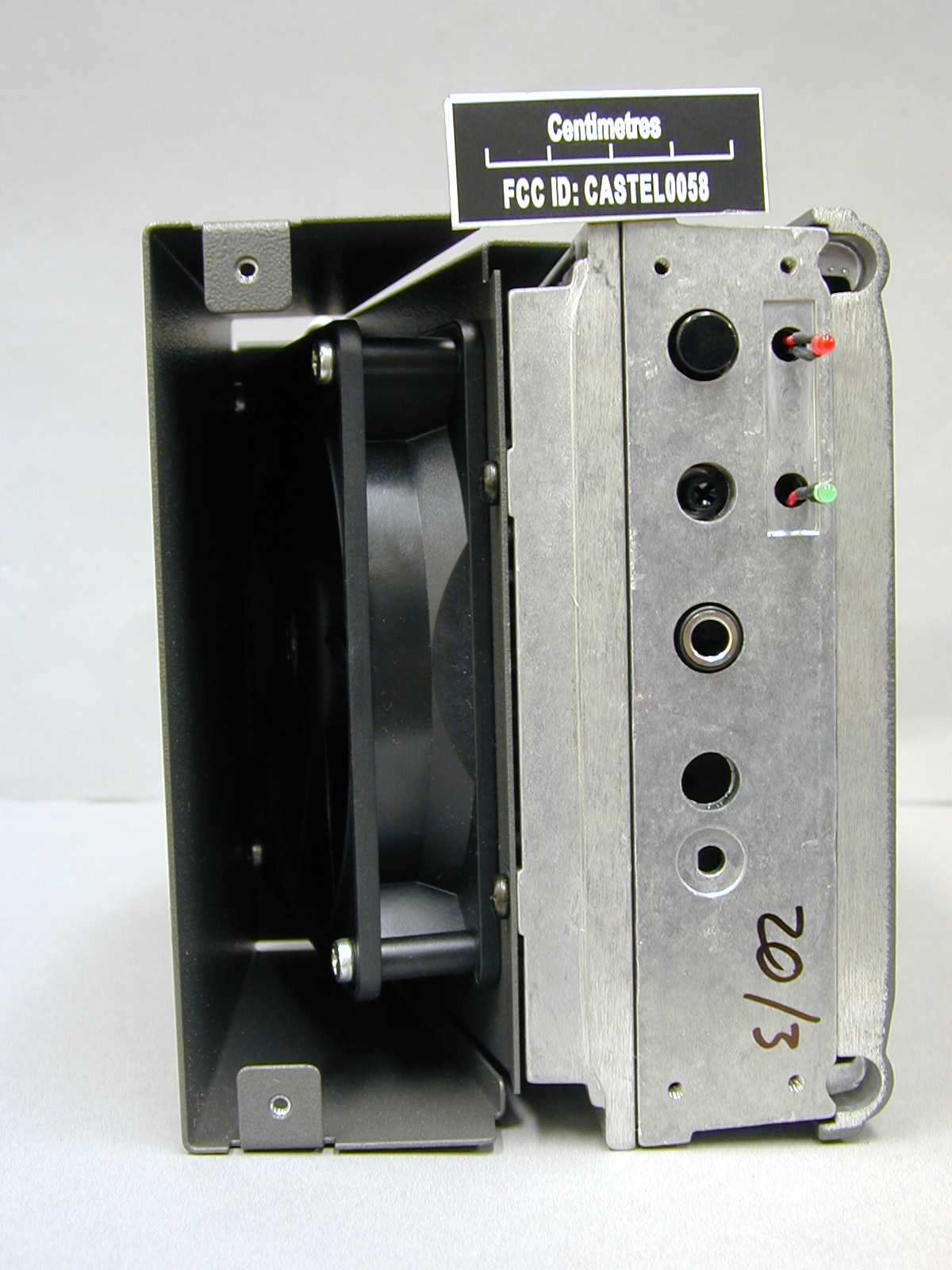
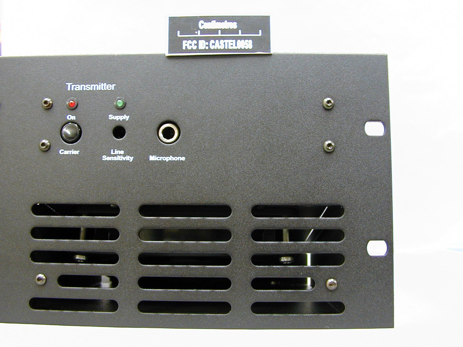
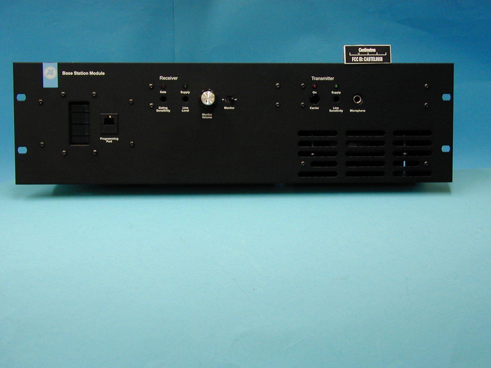
CASTEL0058Base Station Transmitter
Tait International Limited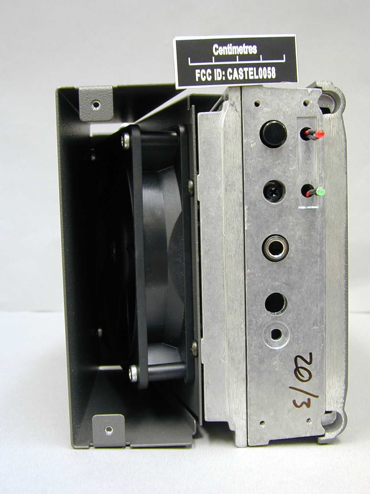
Click to zoom
Application Details
- Equipment Class
- TNB - Licensed Non-Broadcast Station Transmitter
- Date of Grant
- Jul 01, 2002
- Application Purpose
- Original Equipment
- Date of Application
- May 07, 2002
- Equipment Note
- Base Station Transmitter
- Frequency Range
- 480.00000000 - 520.00000000
- Company
- Tait International Limited
- Country
- New Zealand
Documents & Files
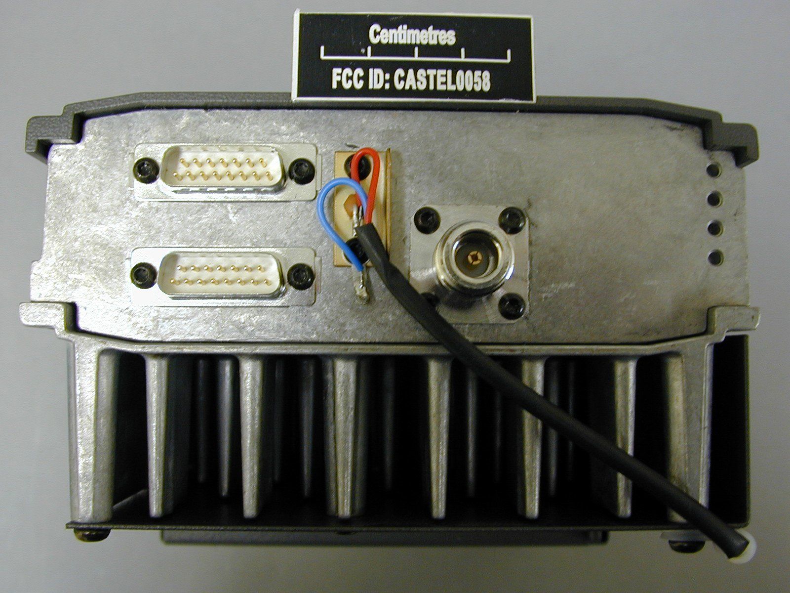

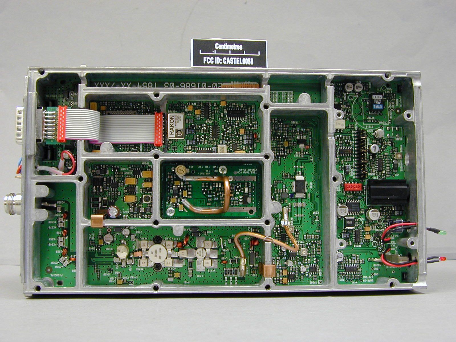
Document Text
Text extracted from the exhibit documents filed with the FCC. Open a document above to read the original.
Users Manual
M800 SL2FI Copyright TEL01/03/02 Part FInstallation This part of the manual is divided into the sections listed below. These sections give a brief description of the rack mounting and wiring procedures for the T854 . SectionTitlePage 2 2.1 2.2 2.3 2.4 T854 Installation Mounting Power Supply Reverse Polarity & Overvoltage Protection Wiring 1.1 1.1 1.1 1.2 1.2 FigureTitlePage 1.1 1.2 1.3 1.4 Assembly with T803 fitted Assembly without T803 fitted Rear View of Unit - Assembly with T803 fitted Rear View - Cables Connected - Assembly with T803 fitted 1.1 1.2 1.3 1.4 FIIM800 SL2 01/03/02Copyright TEL 2M800 SL2 Installation 2.1Mounting The M800 SL2 unit is shipped ready assembled for fitting into racks. All that is required is for the connection of suitable cables. 2.2Power Supply If a power supply other than an appropriate Tait model is used, ensure that it is capable of providing enough current to drive the T800 system and is also free from excessive ripple or noise. The system should be protected by the use of appropriately rated fuses in the power supply. Note:It is particularly important when the prime power source is a battery that fuses be employed in all supply lines. 2.3Reverse Polarity & Overvoltage Protection A crowbar diode is fitted to all T854 transmitters exciters for protection against connec- tion to a power supply of incorrect polarity. It also provides overvoltage protection from voltage transients caused by lightning strikes. Note:A fuse must be fitted in the power supply line for the diode to provide effec- tive protection. M800 SL2FIII Copyright TEL01/03/02 2.4Wiring The D-range input and output connections are shown in Figure 2.1 and Figure 2.2. Ensure that the cables are not subjected to any stresses due to tight bends or incorrect lengths. Make sure the RF coax cable to the N-type connector is free from sharp bends or twists. If access to the rear of the rack frame is restricted, the cable should be long enough to allow the chassis to be fully withdrawn from the guide. Figure 2.1 T855 D-Range 1 Wiring - Rear View Figure 2.2 T855 D-Range 2 Wiring - Rear View (standard T800-03-0000 kit) Note:Figure 2.2 above shows the standard pin allocations for the T800-03-0000 auxiliary D-range kit. A T800-03 auxiliary D-range kit is also available for special applications requiring custom internal wiring. Line O/P1 Speaker Serial Com Audio 1 RSSI Line O/P4 Line O/P3 Line O/P2 Gate O/P Common 1 N.O. 1 Relay +13.8V Gnd Can be configured as Audio 2 by internal link resistors if required. 10.8 to 16V DC Receiver gate, open collector Power supply, -ve earth Adjustable -50 to +10dBm 4.5V = -100dBm 1V/15dB External/auxiliary audio processing Short together for normal operation Receiver gate relay 1W into 4Ω 1 2 3 4 5 6 7 8 9 10 11 12 13 14 15 Can be configured as Audio 2 by internal link resistors if required. Refer to Part I. 2.0V = -110dBm 0.5V/5dB CH_SLCT 0 CH_SLCT 1 CH_SLCT 2 CH_SLCT 3 CH_SLCT 4 CH_SLCT 5 CH_SLCT 6 CH_SLCT 7 GND RX DISABLE CTCSS DISABLE SERIAL COM AUX-OUT 0 AUX-OUT 1 AUX-OUT 2 1 2 3 4 5 6 7 8 9 10 11 12 13 14 15 Open drain type; capable of sinking 2.25mA via 2k2Ω; V max. = 5V ds FIVM800 SL2 01/03/02Copyright TEL M800 SL2 T856/857 Installation F2.1 Copyright TEL 01/03/02 T856/857 Installation220-01138-00Assembly with T803 fitted F2.2 T856/857 Installation M800 SL2 01/03/02 Copyright TEL T856/857 Installation220-01138-00Assembly without T803 fitted
Block Diagram
M800 SL2CI Copyright TEL01/03/02 Part CT854 Transmitter This part of the manual is divided into six sections, as listed below. There is a detailed table of contents at the start of each section. SectionTitle 1General Information 2Circuit Operation 3Initial Tuning & Adjustment 4Functional Testing 5Fault Finding 6PCB Information CIIM800 SL2 01/03/02Copyright TEL M800 SL2T854 General InformationC1.1 Copyright TEL01/03/02 1T854 General Information This section provides a brief description of the T854 transmitter, along with detailed specifications and a list of types available. The following topics are covered in this section. SectionTitlePage 1.1Introduction1.7 1.2 1.2.1 1.2.2 1.2.3 1.2.4 1.2.4.1 1.2.4.2 1.2.4.3 1.2.5 1.2.6 1.2.6.1 1.2.6.2 1.2.6.3 Specifications Introduction General RF Section Audio Processor Inputs Modulation Characteristics CTCSS Microcontroller Te s t S t a n d a rd s European Telecommunication Standard DTI CEPT Recommendation T/R-24-01 Telecommunications Industry Association 1.8 1.8 1.8 1.9 1.10 1.10 1.11 1.11 1.11 1.12 1.12 1.12 1.12 1.3Product Codes1.13 1.4T854 Standard Product Range1.14 FigureTitlePage 1.1T854 Main Circuit Block Identification1.4 1.2T854 Front Panel Controls1.4 C1.2T854 General InformationM800 SL2 01/03/02Copyright TEL M800 SL2T854 General InformationC1.3 Copyright TEL01/03/02 Figure 1.1 T854 Main Circuit Block Identification replace this page with A3 8500C1xx.fm C1.4T854 General InformationM800 SL2 01/03/02Copyright TEL Figure 1.2 T854 Front Panel Controls replace this page with A3 8500C1xx.fm M800 SL2T854 General InformationC1.5 Copyright TEL01/03/02 1.1Introduction The T854 is a synthesised, microprocessor controlled FM base station transmitter designed for single or multichannel operation in the 400 to 520MHz frequency range 1 with a standard power output of 25W. The RF section of the transmitter comprises a fre- quency synthesiser which provides 100mW of frequency modulated RF drive to a two stage, wide band output driver followed by a 25W power supply. A thermal shutdown feature is provided in the T854 in case operating temperatures exceed acceptable levels. The T854 is rated for continuous operation. The T854 is rated for a continuous output power of 25W at +60°C. This is achieved via a high capacity heatsink, electric fan and shroud. The fan draws air across the heatsink to dissipate the heat. The heatsink replaces one of the usual T800 covers. A wide selection of audio characteristics may be obtained from the audio processor. Optional circuit blocks are an audio compressor and a pre-emphasis stage. They can be bypassed or linked to one or both audio inputs, and then back into the remaining audio circuitry in almost any combination. All audio processor options are link selectable. The synthesiser frequency is programmed via the serial communications port. Eight channel select lines are accessible via an optional D-range connector (D-range 2 - T800-03-0000) at the rear of the set. All components except those of the VCO are mounted on a single PCB. This is secured to a die-cast chassis which is divided into compartments to individually shield each sec- tion of circuitry. Access to the PCB is primarily through the top cover of the radio, as all components are mounted on the top side of the PCB. There is provision within the chas- sis to mount small option PCBs. The front panel controls include line sensitivity, microphone socket and carrier switch. This switch turns on the carrier (unmodulated) as an aid to servicing. The T854 is designed to be part of the slimline frame. 1. Although capable of operating over the 400-520MHz frequency range, the T854 and T857 have an 8MHz switching range (see Section 1.2.3 and Section 3.1). C1.6T854 General InformationM800 SL2 01/03/02Copyright TEL 1.2Specifications 1.2.1Introduction The performance figures given are minimum figures, unless otherwise indicated, for equipment tuned with the maximum switching range and operating at standard room temperature (+22°C to +28°C) and standard test voltage (13.8V DC). Where applicable, the test methods used to obtain the following performance figures are those described in the EIA and ETS specifications. However, there are several parameters for which performance according to the CEPT specification is given. Refer to Section 1.2.6 for details of test standards. Details of test methods and the conditions which apply for Type Approval testing in all countries can be obtained from Tait Electronics Ltd. The terms "wide bandwidth", "mid bandwidth" and "narrow bandwidth" used in this and following sections are defined in the following table. 1.2.2General Number Of Channels.. 128 (standard) 1 Supply Voltage: Operating Voltage .. 10.8 to 16V DC Standard Test Voltage .. 13.8V DC Polarity .. negative earth only Polarity Protection .. crowbar diode Line Keying Supply (if required) .. -50V DC Supply Current: Transmit- T854.. 5.5A (typical) Standby - T854.. 165mA (typical) Operating Temperature Range .. -20°C to +60°C Channel Spacing Modulation 100% Deviation Receiver IF Bandwidth Wide Bandwidth25kHz±5.0kHz15.0kHz Mid Bandwidth20kHz±4.0kHz12.0kHz Narrow Bandwidth12.5kHz±2.5kHz7.5kHz 1. Additional channels may be factory programmed. Contact your nearest Tait Dealer or Customer Service Organisation. M800 SL2T854 General InformationC1.7 Copyright TEL01/03/02 Overall Dimensions: Height .. 132mm Width .. 480mm Depth .. 335mm Weight with Tone Remote .. 16kg Weight without Tone Remote .. 13kg Time-Out Timer (optional) .. 0 to 5 minutes 1 adjustable in 10 sec- ond steps Tail Timer .. 0 to 5 seconds adjustable in 100ms 2 steps Transmit Key Time.. <30ms Transmit Lockout Timer.. 0 to 1 minute adjustable in 10 second steps 1.2.3RF Section Frequency Range .. 400-520MHz (refer to Section 1.4 and Section 1.5) Modulation Type .. FM Frequency Increment .. 5 or 6.25kHz Switching Range .. 8MHz (i.e. ±4MHz from the centre frequency) Load Impedance .. 50 ohms Frequency Stability.. ±1ppm, -20°C to +60°C (s…
Text truncated - open the document above for the full version.
Cover Letter(s)
TELTEST Laboratories Tait Electronics Ltd PO Box 1645 558 Wairakei Road Christchurch New Zealand Phone:(64) (3) 3583399 Fax:(64) (3) 3580432 8 th May 2002 To whom it may concern T854-36-7200 CONFIDENTIALITY REQUEST Reference rule sections 0.457 (d) (ii) and pursuant to rule section 0.459 (a) confidentiality is requested as follows: Specific Information: Schematics & PCB Layout The schematics and PCB layouts contain trade secret information which is not made routinely available to the public or to our competitors. Disclosure of this information could result in an unfair advantage to our competitors. It should be treated as confidential for the duration of effectiveness of the Grant Of Authorisation. The attached file is called: T854_PCBSchem.zip Your’s faithfully, Marcus Ludwig (Compliance Laboratory Technician)
Cover Letter(s)
TELTEST Laboratories Tait Electronics Ltd PO Box 1645 558 Wairakei Road Christchurch New Zealand Phone:(64) (3) 3583399 Fax:(64) (3) 3580432 8 th May 2002 To whom it may concern T854-36-7200 The following information is in the Service Manual provided as attachment T854_Text.pdf (T854_Service_Setup.zip), and can be found in Section C1 T854 General Information, C1.12 (Standard Product Range) Caution:T854-XX-XXXX Product Types The 406 to 406.1MHz frequency range is reserved worldwide for use by Distress Beacons. Do not program Transmit Channels to operate in this frequency range. Your’s faithfully, Marcus Ludwig Compliance Laboratory Technician
Cover Letter(s)
TELTEST Laboratories Tait Electronics Ltd PO Box 1645 558 Wairakei Road Christchurch New Zealand Phone:(64) (3) 3583399 Fax:(64) (3) 3580432 24 th June 2002 To whom it may concern: Calculation for the Emission Designator - T854-36-7200 CASTEL0058 / EA998230 The emission designator was calculated from the Steady State Modulation Limiting data for wide and narrow bandwidths. The (theoretical value) is included to show that this sample is within specification Narrow Bandwidth: Formula: Bn = 2M+2DK K=1M=3KHzD= 2.33KHz (2.5KHz) Result: Bn = 10K66F3E (11K0F3E) Wide Bandwidth: Formula: Bn = 2M+2DK K=1M=3KHzD= 4.78KHz (5.0KHz) Result: Bn= 15K56F3E (16K0F3E) Your’s faithfully, Des Fox Compliance Coordinator
Cover Letter(s)
TELTEST Laboratories Tait Electronics Ltd PO Box 1645 558 Wairakei Road Christchurch New Zealand Phone:(64) (3) 3583399 Fax:(64) (3) 3580432 25 June 2002 To whom it may concern T854-36-7200 CONFIDENTIALITY REQUEST Clarification Reference rule sections 0.457 (d) (ii) and pursuant to rule section 0.459 (a) confidentiality is requested as follows: Specific Information: Schematics & PCB Layout The schematics and PCB layouts contain trade secret information which is not made routinely available to the public or to our competitors. Disclosure of this information could result in an unfair advantage to our competitors. It should be treated as confidential for the duration of effectiveness of the Grant Of Authorisation. The attached file is called: T854_PCB_A.pdf This file also contains Parts List Information, for this reason I am obliged to mark the Parts List Exhibit as confidential, so as to protect the confidential PCB Grid Reference information on this file, from the market Your’s faithfully, Des Fox (Compliance Coordinator)
Operational Description
M800 SL2CI Copyright TEL01/03/02 Part CT854 Transmitter This part of the manual is divided into six sections, as listed below. There is a detailed table of contents at the start of each section. SectionTitle 1General Information 2Circuit Operation 3Initial Tuning & Adjustment 4Functional Testing 5Fault Finding 6PCB Information CIIM800 SL2 01/03/02Copyright TEL M800 SL2T854 General InformationC1.1 Copyright TEL01/03/02 1T854 General Information This section provides a brief description of the T854 transmitter, along with detailed specifications and a list of types available. The following topics are covered in this section. SectionTitlePage 1.1Introduction1.7 1.2 1.2.1 1.2.2 1.2.3 1.2.4 1.2.4.1 1.2.4.2 1.2.4.3 1.2.5 1.2.6 1.2.6.1 1.2.6.2 1.2.6.3 Specifications Introduction General RF Section Audio Processor Inputs Modulation Characteristics CTCSS Microcontroller Te s t S t a n d a rd s European Telecommunication Standard DTI CEPT Recommendation T/R-24-01 Telecommunications Industry Association 1.8 1.8 1.8 1.9 1.10 1.10 1.11 1.11 1.11 1.12 1.12 1.12 1.12 1.3Product Codes1.13 1.4T854 Standard Product Range1.14 FigureTitlePage 1.1T854 Main Circuit Block Identification1.4 1.2T854 Front Panel Controls1.4 C1.2T854 General InformationM800 SL2 01/03/02Copyright TEL M800 SL2T854 General InformationC1.3 Copyright TEL01/03/02 Figure 1.1 T854 Main Circuit Block Identification replace this page with A3 8500C1xx.fm C1.4T854 General InformationM800 SL2 01/03/02Copyright TEL Figure 1.2 T854 Front Panel Controls replace this page with A3 8500C1xx.fm M800 SL2T854 General InformationC1.5 Copyright TEL01/03/02 1.1Introduction The T854 is a synthesised, microprocessor controlled FM base station transmitter designed for single or multichannel operation in the 400 to 520MHz frequency range 1 with a standard power output of 25W. The RF section of the transmitter comprises a fre- quency synthesiser which provides 100mW of frequency modulated RF drive to a two stage, wide band output driver followed by a 25W power supply. A thermal shutdown feature is provided in the T854 in case operating temperatures exceed acceptable levels. The T854 is rated for continuous operation. The T854 is rated for a continuous output power of 25W at +60°C. This is achieved via a high capacity heatsink, electric fan and shroud. The fan draws air across the heatsink to dissipate the heat. The heatsink replaces one of the usual T800 covers. A wide selection of audio characteristics may be obtained from the audio processor. Optional circuit blocks are an audio compressor and a pre-emphasis stage. They can be bypassed or linked to one or both audio inputs, and then back into the remaining audio circuitry in almost any combination. All audio processor options are link selectable. The synthesiser frequency is programmed via the serial communications port. Eight channel select lines are accessible via an optional D-range connector (D-range 2 - T800-03-0000) at the rear of the set. All components except those of the VCO are mounted on a single PCB. This is secured to a die-cast chassis which is divided into compartments to individually shield each sec- tion of circuitry. Access to the PCB is primarily through the top cover of the radio, as all components are mounted on the top side of the PCB. There is provision within the chas- sis to mount small option PCBs. The front panel controls include line sensitivity, microphone socket and carrier switch. This switch turns on the carrier (unmodulated) as an aid to servicing. The T854 is designed to be part of the slimline frame. 1. Although capable of operating over the 400-520MHz frequency range, the T854 and T857 have an 8MHz switching range (see Section 1.2.3 and Section 3.1). C1.6T854 General InformationM800 SL2 01/03/02Copyright TEL 1.2Specifications 1.2.1Introduction The performance figures given are minimum figures, unless otherwise indicated, for equipment tuned with the maximum switching range and operating at standard room temperature (+22°C to +28°C) and standard test voltage (13.8V DC). Where applicable, the test methods used to obtain the following performance figures are those described in the EIA and ETS specifications. However, there are several parameters for which performance according to the CEPT specification is given. Refer to Section 1.2.6 for details of test standards. Details of test methods and the conditions which apply for Type Approval testing in all countries can be obtained from Tait Electronics Ltd. The terms "wide bandwidth", "mid bandwidth" and "narrow bandwidth" used in this and following sections are defined in the following table. 1.2.2General Number Of Channels.. 128 (standard) 1 Supply Voltage: Operating Voltage .. 10.8 to 16V DC Standard Test Voltage .. 13.8V DC Polarity .. negative earth only Polarity Protection .. crowbar diode Line Keying Supply (if required) .. -50V DC Supply Current: Transmit- T854.. 5.5A (typical) Standby - T854.. 165mA (typical) Operating Temperature Range .. -20°C to +60°C Channel Spacing Modulation 100% Deviation Receiver IF Bandwidth Wide Bandwidth25kHz±5.0kHz15.0kHz Mid Bandwidth20kHz±4.0kHz12.0kHz Narrow Bandwidth12.5kHz±2.5kHz7.5kHz 1. Additional channels may be factory programmed. Contact your nearest Tait Dealer or Customer Service Organisation. M800 SL2T854 General InformationC1.7 Copyright TEL01/03/02 Overall Dimensions: Height .. 132mm Width .. 480mm Depth .. 335mm Weight with Tone Remote .. 16kg Weight without Tone Remote .. 13kg Time-Out Timer (optional) .. 0 to 5 minutes 1 adjustable in 10 sec- ond steps Tail Timer .. 0 to 5 seconds adjustable in 100ms 2 steps Transmit Key Time.. <30ms Transmit Lockout Timer.. 0 to 1 minute adjustable in 10 second steps 1.2.3RF Section Frequency Range .. 400-520MHz (refer to Section 1.4 and Section 1.5) Modulation Type .. FM Frequency Increment .. 5 or 6.25kHz Switching Range .. 8MHz (i.e. ±4MHz from the centre frequency) Load Impedance .. 50 ohms Frequency Stability.. ±1ppm, -20°C to +60°C (s…
Text truncated - open the document above for the full version.
Operational Description
M800 SL2FI Copyright TEL01/03/02 Part FInstallation This part of the manual is divided into the sections listed below. These sections give a brief description of the rack mounting and wiring procedures for the T854 . SectionTitlePage 2 2.1 2.2 2.3 2.4 T854 Installation Mounting Power Supply Reverse Polarity & Overvoltage Protection Wiring 1.1 1.1 1.1 1.2 1.2 FigureTitlePage 1.1 1.2 1.3 1.4 Assembly with T803 fitted Assembly without T803 fitted Rear View of Unit - Assembly with T803 fitted Rear View - Cables Connected - Assembly with T803 fitted 1.1 1.2 1.3 1.4 FIIM800 SL2 01/03/02Copyright TEL 2M800 SL2 Installation 2.1Mounting The M800 SL2 unit is shipped ready assembled for fitting into racks. All that is required is for the connection of suitable cables. 2.2Power Supply If a power supply other than an appropriate Tait model is used, ensure that it is capable of providing enough current to drive the T800 system and is also free from excessive ripple or noise. The system should be protected by the use of appropriately rated fuses in the power supply. Note:It is particularly important when the prime power source is a battery that fuses be employed in all supply lines. 2.3Reverse Polarity & Overvoltage Protection A crowbar diode is fitted to all T854 transmitters exciters for protection against connec- tion to a power supply of incorrect polarity. It also provides overvoltage protection from voltage transients caused by lightning strikes. Note:A fuse must be fitted in the power supply line for the diode to provide effec- tive protection. M800 SL2FIII Copyright TEL01/03/02 2.4Wiring The D-range input and output connections are shown in Figure 2.1 and Figure 2.2. Ensure that the cables are not subjected to any stresses due to tight bends or incorrect lengths. Make sure the RF coax cable to the N-type connector is free from sharp bends or twists. If access to the rear of the rack frame is restricted, the cable should be long enough to allow the chassis to be fully withdrawn from the guide. Figure 2.1 T855 D-Range 1 Wiring - Rear View Figure 2.2 T855 D-Range 2 Wiring - Rear View (standard T800-03-0000 kit) Note:Figure 2.2 above shows the standard pin allocations for the T800-03-0000 auxiliary D-range kit. A T800-03 auxiliary D-range kit is also available for special applications requiring custom internal wiring. Line O/P1 Speaker Serial Com Audio 1 RSSI Line O/P4 Line O/P3 Line O/P2 Gate O/P Common 1 N.O. 1 Relay +13.8V Gnd Can be configured as Audio 2 by internal link resistors if required. 10.8 to 16V DC Receiver gate, open collector Power supply, -ve earth Adjustable -50 to +10dBm 4.5V = -100dBm 1V/15dB External/auxiliary audio processing Short together for normal operation Receiver gate relay 1W into 4Ω 1 2 3 4 5 6 7 8 9 10 11 12 13 14 15 Can be configured as Audio 2 by internal link resistors if required. Refer to Part I. 2.0V = -110dBm 0.5V/5dB CH_SLCT 0 CH_SLCT 1 CH_SLCT 2 CH_SLCT 3 CH_SLCT 4 CH_SLCT 5 CH_SLCT 6 CH_SLCT 7 GND RX DISABLE CTCSS DISABLE SERIAL COM AUX-OUT 0 AUX-OUT 1 AUX-OUT 2 1 2 3 4 5 6 7 8 9 10 11 12 13 14 15 Open drain type; capable of sinking 2.25mA via 2k2Ω; V max. = 5V ds FIVM800 SL2 01/03/02Copyright TEL M800 SL2 T856/857 Installation F2.1 Copyright TEL 01/03/02 T856/857 Installation220-01138-00Assembly with T803 fitted F2.2 T856/857 Installation M800 SL2 01/03/02 Copyright TEL T856/857 Installation220-01138-00Assembly without T803 fitted
Operational Description
M800 SL2 T856/857 Installation F2.3 Copyright TEL 01/03/02 T856/857 Installation220-01138-00Rear View of UnitAssembly with T803 fitted
Operational Description
F2.4 T856/857 Installation M800 SL2 01/03/02 Copyright TEL T856/857 Installation220-01138-00Rear View Cables ConnetecdAssembly with T803 fitted M800 SL2 T858/859 Installation F3.1 Copyright TEL 01/03/02 3 T858/859 Installation 3.1 Rack Mounting Caution: If you require continuous operation of the T858, leave the rack moduleposition immediately adjacent to the finned heatsink empty. Thereshould be adequate airflow over the fins at all times. Extra airflow canbe provided by fitting an auxiliary fan kit such as the T800-19-0010(refer to the T800 Ancillary Equipment Service Manual or your nearestTait Dealer or Customer Service Organisation for more details). The T858 and T859 PAs are designedfor use in a standard 483mm rack frameusing Tait M800 SL2 guide rails. Theguide rails are securely mounted to therack frame with front and rear retainingscrews, and the PA is secured into theguide with two (T858) or four (T859)front panel mounting screws. Figure3.1 shows the standard, double widthguide designed for use with the T859,while Figure 3.3 shows how the PA canbe latched in the extended position.For more information on availableguide kits, refer to the T800 AncillaryEquipment Service Manual or yournearest Tait Dealer or Customer ServiceOrganisation. Figure 3.1 T800-45-0001 PA Guide Kit The PA rear panel has three connectors: a BNC for RF input (from an adjacent T857exciter), an N-type for RF output and a D-range for all DC, audio and control connec-tions (refer to Figure 3.2). Figure 3.2 T858/859 Chassis Connectors Figure 3.3 T858/859 PA In Latched Position Note: You will need appropriate extension leads if you wish to carry out anyadjustment procedures with the PA withdrawn from the rack in the latchedposition. Alternatively, disconnect and withdraw the PA and reconnect itbehind the rack. 3.2 Rack Wiring The D-range input and output connections are shown in Figure 3.4. Ensure that thecables are not subjected to any stresses due to tight bends or incorrect lengths.Make sure the RF coax cables to the N-type and BNC connectors are free from sharpbends or twists. If access to the rear of the rack frame is restricted, the cables should belong enough to allow the chassis to be fully withdrawn from the guide. Figure 3.4 T858/859 D-Range Wiring - Rear View Front PanelMounting Holes Rack MountingHoles Rack MountingHoles Rack Mounting Holes N-Type ConnectorBNC Connector D-Range Connector N-Type ConnectorBNC Connector D-Range Connector T858 T859 RF OutputRF InputD-range Top Rail Bottom Rail 1 23 45 6 7 8 9 10 11 12 1314 15 Normally low, floaton alarm conditions.500mA sink capability. Pull low to enablealarm outputs Power supply, -ve earth Will drive a coil meter 10.8 to 16V DC Reverse Power Metering Forward Power Metering Reverse Power AlarmForward Power Alarm Tx Key +13.8V Gnd F3.2 T858/859 Installation M800 SL2 01/03/02 Copyright TEL 3.3 Power Supply If a power supply other than an appropriate Tait model is used, ensure that it is capableof providing enough current to drive the T800 system and is also free from excessiveripple or noise.The system should be protected by the use of appropriately rated fuses in the powersupply.Note: It is particularly important when the prime power source is a battery thatfuses be employed in all supply lines. Caution: Connect the power supply directly to the PA, and not via connector blocks. This will avoid overheating of connector blocks that are not ofthe correct current rating. 3.4 Reverse Polarity & Overvoltage Protection A crowbar diode is fitted to all T858/859 PAs for protection against connection to apower supply of incorrect polarity. It also provides overvoltage protection from voltagetransients caused by lightning strikes.Note: A fuse must be fitted in the power supply line for the diode to provide effec-tive protection.
Test Report
FCC ID: CASTEL0058 TELTEST REPORT: 1734 T854-36-7200 ( Base Station; Transmitter) S/N: 13049181 Page 1 of 34 REPORT NUMBER 1734April 2002 RADIO PERFORMANCE MEASUREMENTS On the T854-36-7200 Base Station Transmitter FCC ID: CASTEL0058 SN: 13049181 In accordance with FCC 47 CFR Part 90 PREPARED BY:Marcus Ludwig ___________________ Test Technician CHECKED & APPROVED BY:SA Crompton ___________________ Laboratory Manager TELTEST LABORATORIES Tait Electronics Ltd PO Box 1645 558 Wairakei Road Christchurch 8005 New Zealand Phone:+64-3-3583399 Fax:+64-3-3580432 FCC ID: CASTEL0058 TELTEST REPORT: 1734 T854-36-7200 ( Base Station; Transmitter) S/N: 13049181 Page 2 of 34 TABLE OF CONTENTS TESTPAGE TRANSMITTER OUTPUT POWER (CONDUCTED) 3 AUDIO FREQUENCY FILTER NOT TESTED 4 TRANSMITTER AUDIO FREQUENCY RESPONSE 5 MODULATION LIMITING 7 MODULATION LIMITING (STEADY STATE) 10 MODULATION LIMITING (INSTANTANEOUS) 12 OCCUPIED BANDWIDTH 14 SPURIOUS EMISSIONS (CONDUCTED) 18 SPURIOUS EMISSIONS (RADIATED) 21 TRANSMITTER FREQUENCY STABILITY ( TEMPERATURE) 24 TRANSMITTER FREQUENCY STABILITY (VOLTAGE) 26 TRANSMITTER TRANSIENT FREQUENCY BEHAVIOUR 27 LIST OF TEST EQUIPMENT 32 FCC ID: CASTEL0058 TELTEST REPORT: 1734 T854-36-7200 ( Base Station; Transmitter) S/N: 13049181 Page 3 of 34 NAME OF TEST:TRANSMITTER O UTPUT POWER (CO NDUCTED) TEST CO NDITIONS:Ambient Temperat ure 16 o C Relative Humidity 61 % Standard Voltage 13.8 V DC SPECIFICATION:FCC 47 CFR 2.1046 GUIDE:TIA/EIA-603 2.2.1 MEASUREMENT PROCEDURE: 1. The Equipment Under Test (EUT) was set up as shown on the following diagram. 2. The coaxial attenuator has an impedance of 50 Ohms. 3. The unmodulated output power was measured with an RF Power meter. MEASUREMENT RESULTS: Manufacturer’s Rated Output Power:25W Switchable: 25 kHz and 12.5 kHz Channel Spacing 495 MHz25 W nominal / 25 kHz25 W nominal / 12.5 kHz POWER (W)24.0023.90 Variation from Nominal (%)-4.00-4.40 Measurement Uncertainty (dB) +0.63 -0.68 LIMIT CLAUSE:FCC 47 CFR 80.215 Radio Type:Base Station Frequency Band:421 MHz ~ 512 MHz (n) The output power shall not exceed by more than 20% the manufacturer’s rated output power for the particular transmitter. TEST SETUP:See page 32 for Test Equipment information. POWER SENSOR POWER METER 15 16 EUT DC LOAD 70 FCC ID: CASTEL0058 TELTEST REPORT: 1734 T854-36-7200 ( Base Station; Transmitter) S/N: 13049181 Page 4 of 34 NAME OF TEST:AUDIO FREQ UENCY FILTER RESPO NSE NOT TESTED TEST CO NDITIONS:Ambient Temperat ure o C Relative Humidity% Standard Voltage V DC SPECIFICATION:FCC 47 CFR 2.1047 GUIDE:TIA/EIA-603 2.2.15 MEASUREMENT PROCEDURE: This test was not carried out as the EUT meets the emission limits specified in §90.210. MEASUREMENT RESULTS: See Occupied Bandwidth tests on page 32. LIMIT CLAUSE:FCC 47 CFR 90.211 (a) (a) Transmitters utilizing analog emissions that are equipped with an audio low-pass filter must meet the emission limitations specified in §90.210.... TEST SETUP:See page 32 – Occupied Bandwidth FCC ID: CASTEL0058 TELTEST REPORT: 1734 T854-36-7200 ( Base Station; Transmitter) S/N: 13049181 Page 5 of 34 NAME OF TEST:TRANSMITTER AUDIO FREQ UENCY RESPO NSE PRE-EMPHASIS TEST CO NDITIONS:Ambient Temperat ure20 o C Relative Humidity60 % Standard Voltage13.8 V DC SPECIFICATION:FCC 47 CFR 2.1047 (a) GUIDE:TIA/EIA-603 2.2.6 MEASUREMENT PROCEDURE: 1. The Equipment Under Test (EUT) was set up as shown on the following diagram. 2. An audio input tone of 1000Hz was applied with the level set to obtain 20% of maximum deviation. This was used as the 0dB reference point. 3. The AF was varied while the audio level was held constant. 4. The response in dB relative to 1000Hz was measured. MEASUREMENT RESULTS:See the plot on the following page. LIMIT CLAUSE:TIA/EIA-603 2.2.6 TEST SETUP:See page 32 for Test Equipment information. AF GEN EUTCABLEATTEN MOD ANAL 13 11 8338 DC FCC ID: CASTEL0058 TELTEST REPORT: 1734 T854-36-7200 ( Base Station; Transmitter) S/N: 13049181 Page 6 of 34 NAME OF TEST:TRANSMI…
Text truncated - open the document above for the full version.
Contact Information
Applicant
Linda White(Standards and Regulatory Manager)
Technical Contact
Tait Electronics LtdStephen A Crompton
558 Wairakei Road · Christchurch · New Zealand
Non-Technical Contact
Tait Electronics LtdStephen A Crompton
Technical Specifications
| # | Rule Parts | Frequency Range | Power Output | Emission | Tolerance |
|---|---|---|---|---|---|
| 2 | 9 | 480 MHz - 520 MHz | 25 W | 16K0F3E | 1 ppm |
Other Applications from Tait International Limited
CASTBCHGB
May 12, 2026Base Station Transceiver
Equipment Class
TNB - Licensed Non-Broadcast Station Transmitter
CASTBCHGA
May 12, 2026Base Station Transceiver
Equipment Class
TNB - Licensed Non-Broadcast Station Transmitter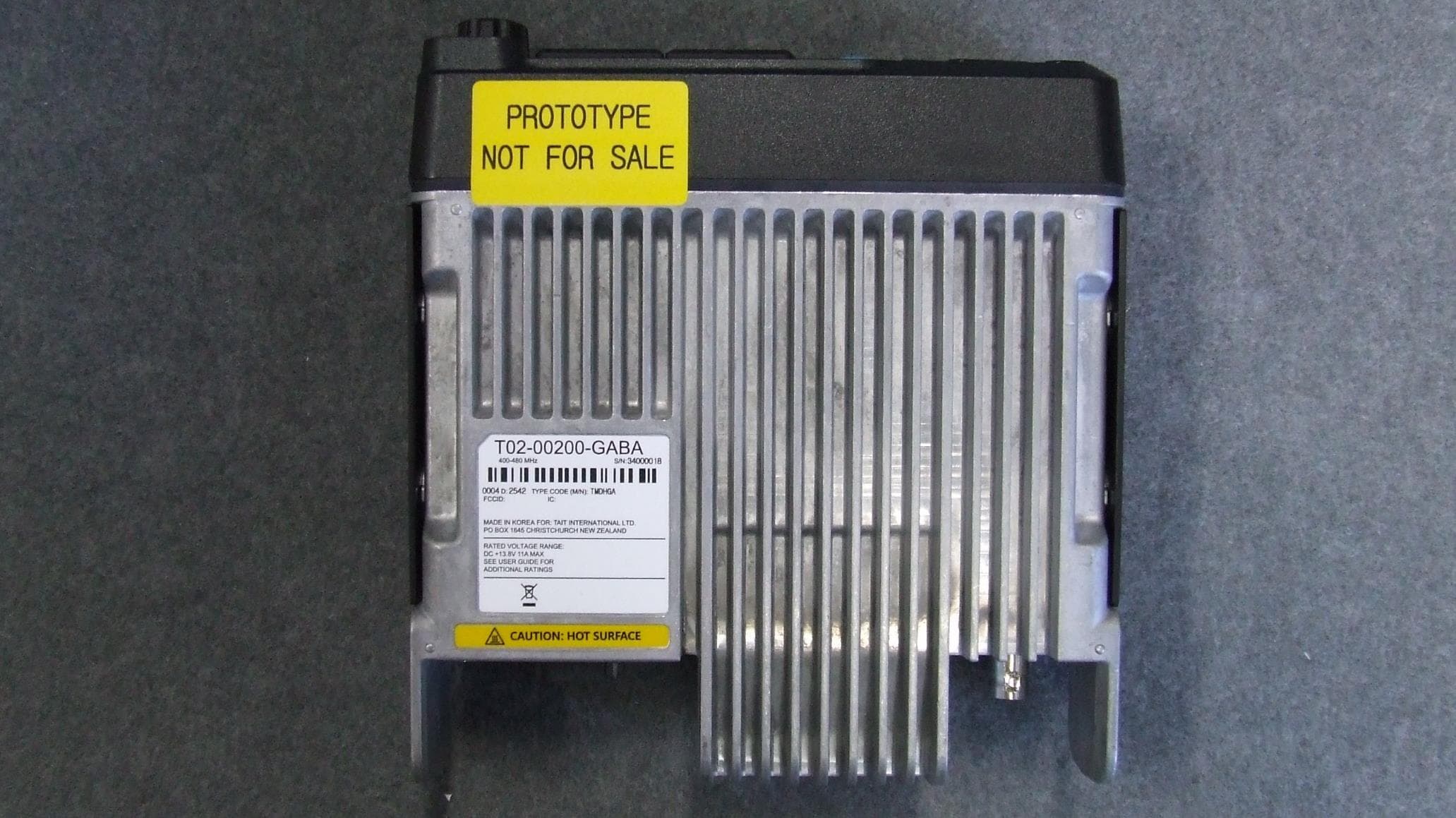
CASTMDHGA
Feb 04, 2026Mobile Transceiver
Equipment Class
TNB - Licensed Non-Broadcast Station Transmitter
CASTPJHGB
Jan 15, 2026Portable Transceiver
Equipment Class
TNF - Licensed Non-Broadcast Transmitter Held to Face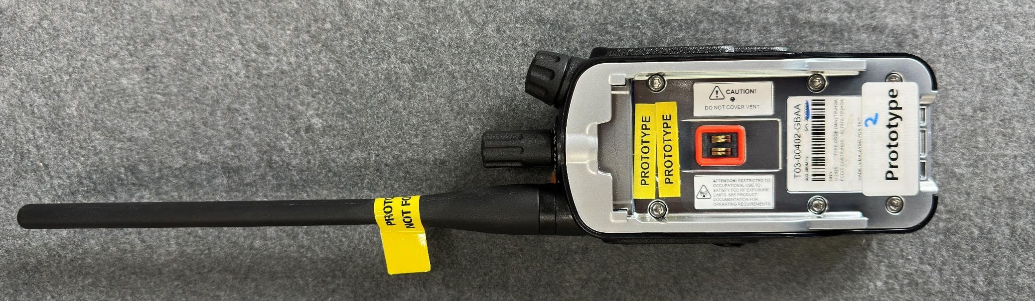
CASTPJHGA
Jan 15, 2026Portable Transceiver
Equipment Class
DSS - Part 15 Spread Spectrum Transmitter