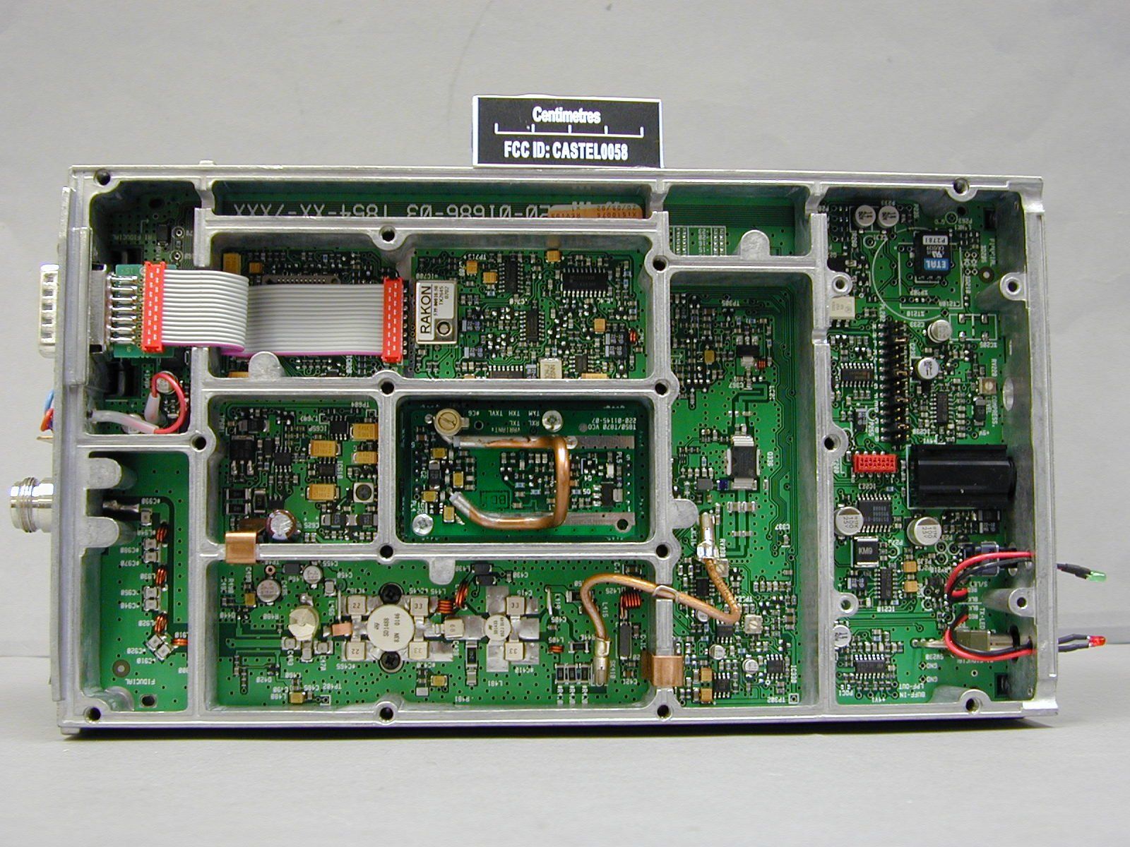
CASTEL0059Base Station Transmitter
Tait International Limited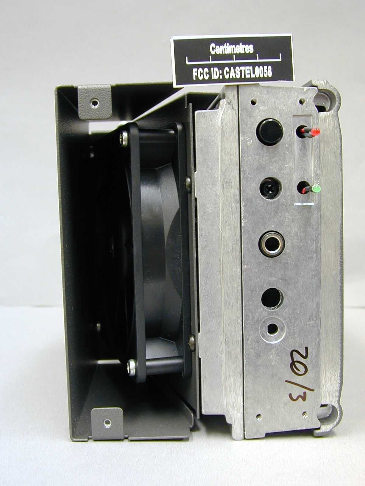
Click to zoom
Application Details
- Equipment Class
- TNB - Licensed Non-Broadcast Station Transmitter
- Date of Grant
- Jul 31, 2002
- Application Purpose
- Original Equipment
- Date of Application
- Jun 11, 2002
- Equipment Note
- Base Station Transmitter
- Frequency Range
- 400.00000000 - 440.00000000
- Company
- Tait International Limited
- Country
- New Zealand
Documents & Files
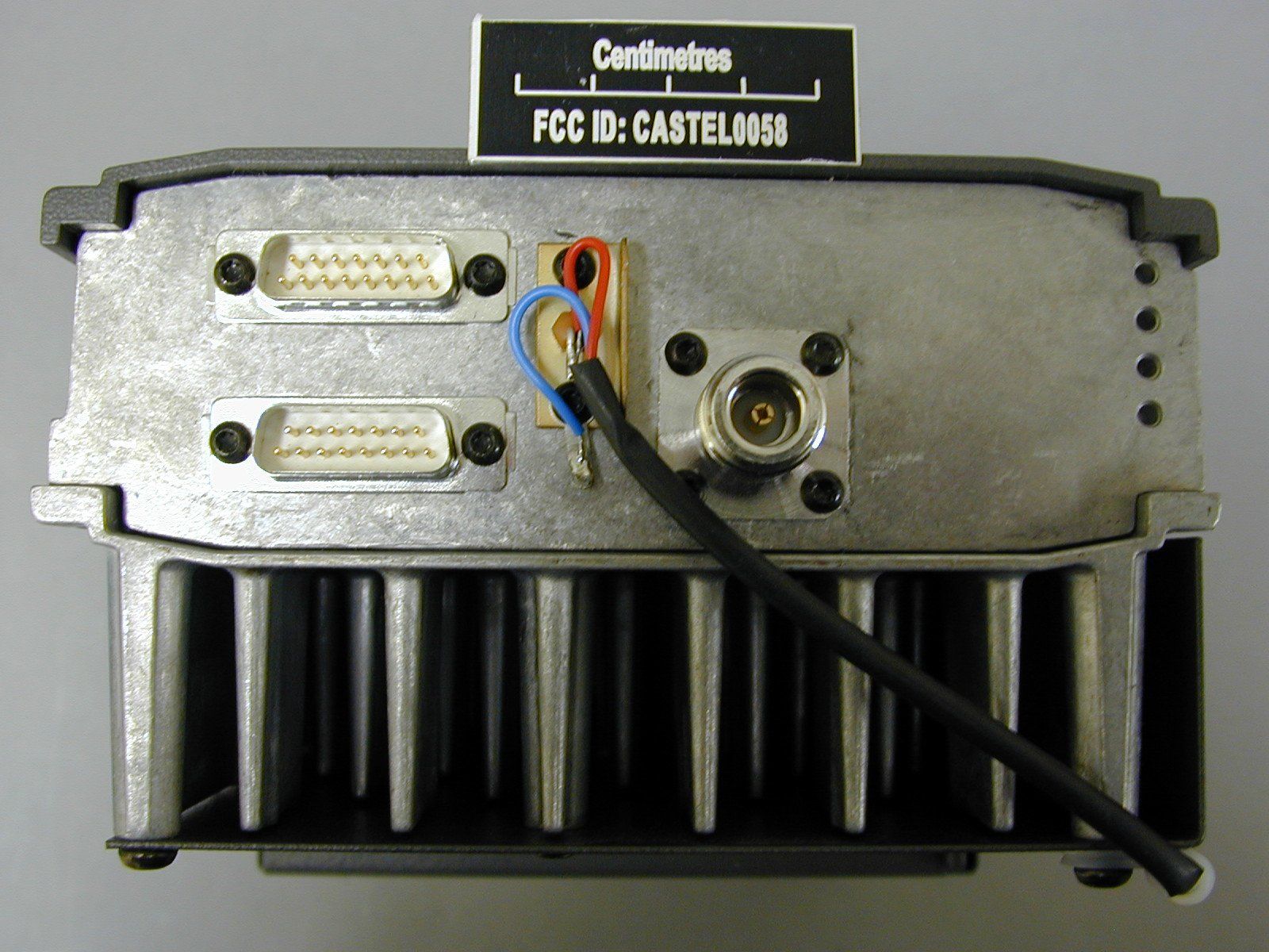
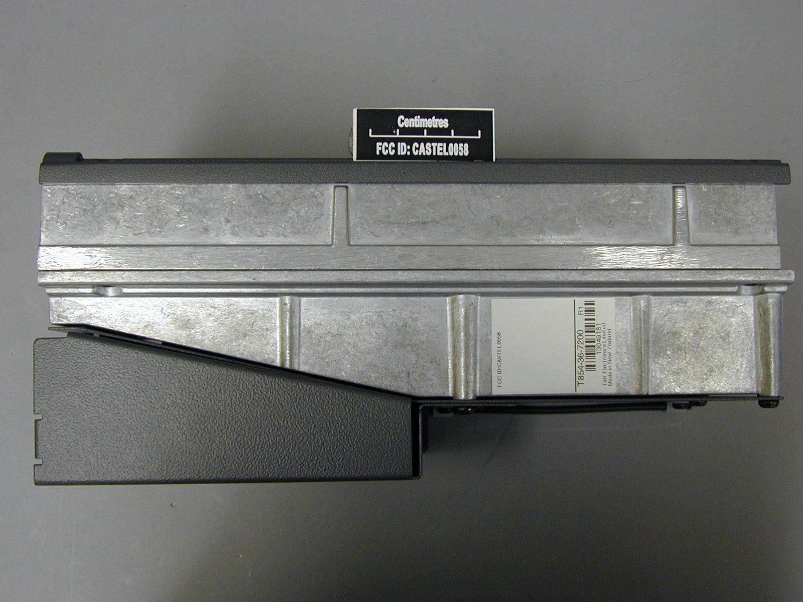
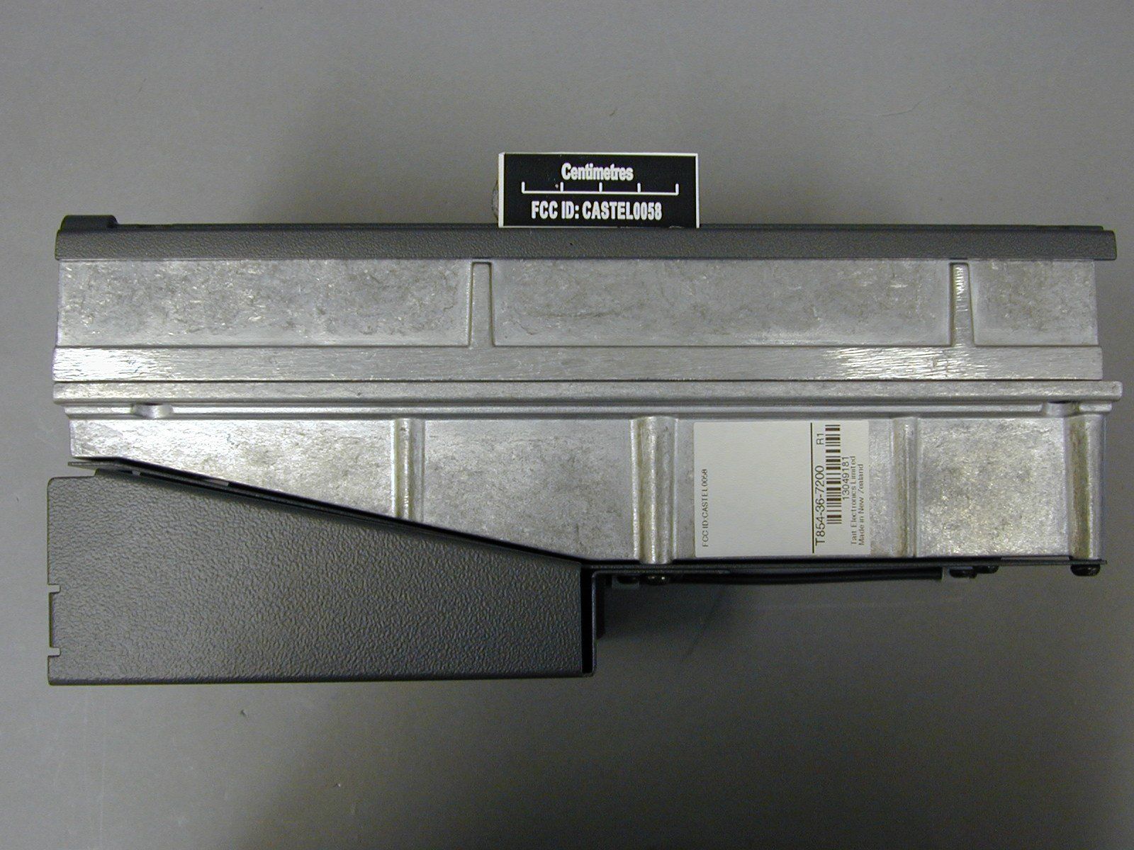
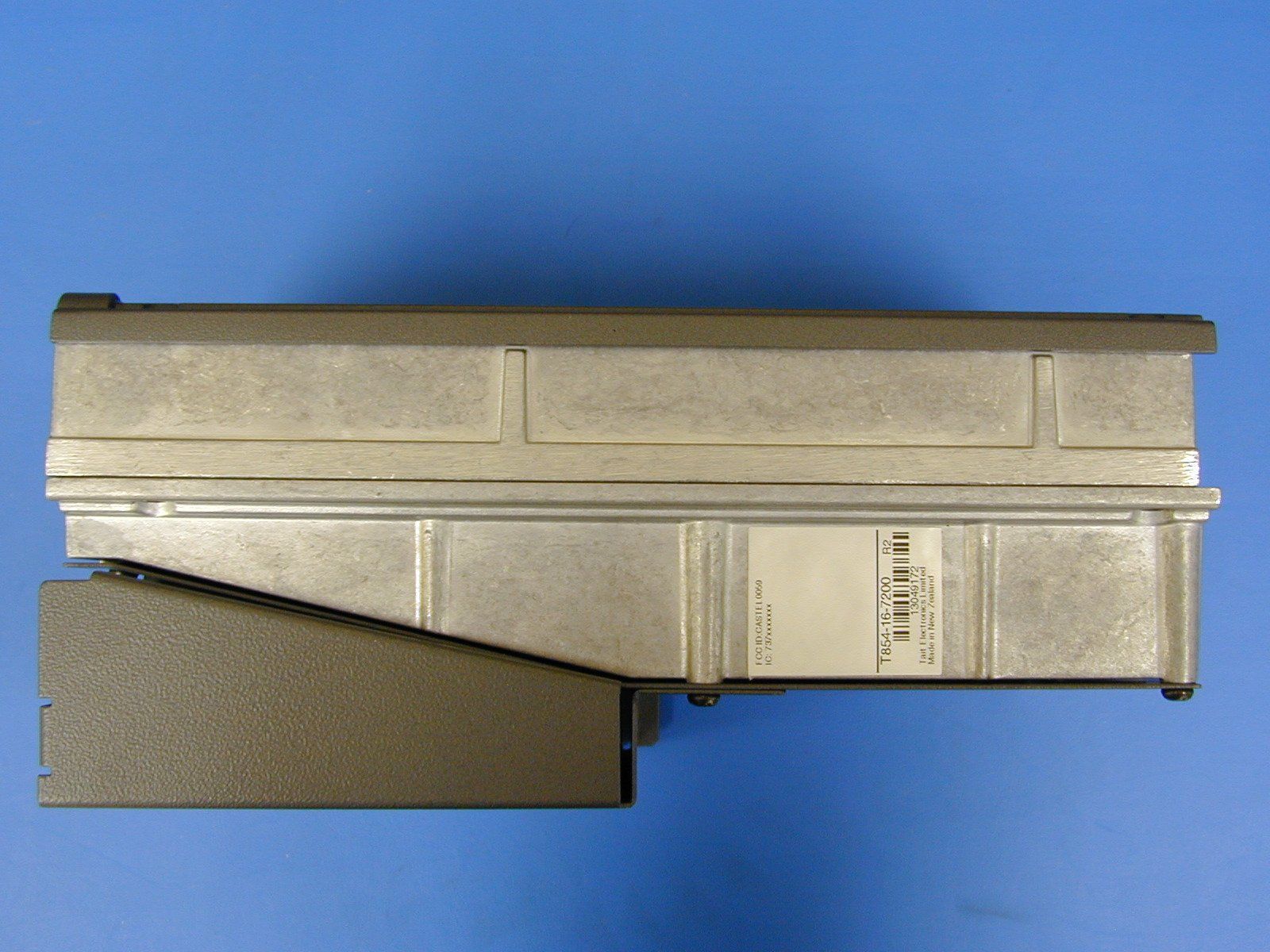
Document Text
Text extracted from the exhibit documents filed with the FCC. Open a document above to read the original.
Users Manual
M800 SL2CI Copyright TEL01/03/02 Part CT854 Transmitter This part of the manual is divided into six sections, as listed below. There is a detailed table of contents at the start of each section. SectionTitle 1General Information 2Circuit Operation 3Initial Tuning & Adjustment 4Functional Testing 5Fault Finding 6PCB Information CIIM800 SL2 01/03/02Copyright TEL M800 SL2T854 General InformationC1.1 Copyright TEL01/03/02 1T854 General Information This section provides a brief description of the T854 transmitter, along with detailed specifications and a list of types available. The following topics are covered in this section. SectionTitlePage 1.1Introduction1.7 1.2 1.2.1 1.2.2 1.2.3 1.2.4 1.2.4.1 1.2.4.2 1.2.4.3 1.2.5 1.2.6 1.2.6.1 1.2.6.2 1.2.6.3 Specifications Introduction General RF Section Audio Processor Inputs Modulation Characteristics CTCSS Microcontroller Te s t S t a n d a rd s European Telecommunication Standard DTI CEPT Recommendation T/R-24-01 Telecommunications Industry Association 1.8 1.8 1.8 1.9 1.10 1.10 1.11 1.11 1.11 1.12 1.12 1.12 1.12 1.3Product Codes1.13 1.4T854 Standard Product Range1.14 FigureTitlePage 1.1T854 Main Circuit Block Identification1.4 1.2T854 Front Panel Controls1.4 C1.2T854 General InformationM800 SL2 01/03/02Copyright TEL M800 SL2T854 General InformationC1.3 Copyright TEL01/03/02 Figure 1.1 T854 Main Circuit Block Identification replace this page with A3 8500C1xx.fm C1.4T854 General InformationM800 SL2 01/03/02Copyright TEL Figure 1.2 T854 Front Panel Controls replace this page with A3 8500C1xx.fm M800 SL2T854 General InformationC1.5 Copyright TEL01/03/02 1.1Introduction The T854 is a synthesised, microprocessor controlled FM base station transmitter designed for single or multichannel operation in the 400 to 520MHz frequency range 1 with a standard power output of 25W. The RF section of the transmitter comprises a fre- quency synthesiser which provides 100mW of frequency modulated RF drive to a two stage, wide band output driver followed by a 25W power supply. A thermal shutdown feature is provided in the T854 in case operating temperatures exceed acceptable levels. The T854 is rated for continuous operation. The T854 is rated for a continuous output power of 25W at +60°C. This is achieved via a high capacity heatsink, electric fan and shroud. The fan draws air across the heatsink to dissipate the heat. The heatsink replaces one of the usual T800 covers. A wide selection of audio characteristics may be obtained from the audio processor. Optional circuit blocks are an audio compressor and a pre-emphasis stage. They can be bypassed or linked to one or both audio inputs, and then back into the remaining audio circuitry in almost any combination. All audio processor options are link selectable. The synthesiser frequency is programmed via the serial communications port. Eight channel select lines are accessible via an optional D-range connector (D-range 2 - T800-03-0000) at the rear of the set. All components except those of the VCO are mounted on a single PCB. This is secured to a die-cast chassis which is divided into compartments to individually shield each sec- tion of circuitry. Access to the PCB is primarily through the top cover of the radio, as all components are mounted on the top side of the PCB. There is provision within the chas- sis to mount small option PCBs. The front panel controls include line sensitivity, microphone socket and carrier switch. This switch turns on the carrier (unmodulated) as an aid to servicing. The T854 is designed to be part of the slimline frame. 1. Although capable of operating over the 400-520MHz frequency range, the T854 and T857 have an 8MHz switching range (see Section 1.2.3 and Section 3.1). C1.6T854 General InformationM800 SL2 01/03/02Copyright TEL 1.2Specifications 1.2.1Introduction The performance figures given are minimum figures, unless otherwise indicated, for equipment tuned with the maximum switching range and operating at standard room temperature (+22°C to +28°C) and standard test voltage (13.8V DC). Where applicable, the test methods used to obtain the following performance figures are those described in the EIA and ETS specifications. However, there are several parameters for which performance according to the CEPT specification is given. Refer to Section 1.2.6 for details of test standards. Details of test methods and the conditions which apply for Type Approval testing in all countries can be obtained from Tait Electronics Ltd. The terms "wide bandwidth", "mid bandwidth" and "narrow bandwidth" used in this and following sections are defined in the following table. 1.2.2General Number Of Channels.. 128 (standard) 1 Supply Voltage: Operating Voltage .. 10.8 to 16V DC Standard Test Voltage .. 13.8V DC Polarity .. negative earth only Polarity Protection .. crowbar diode Line Keying Supply (if required) .. -50V DC Supply Current: Transmit- T854.. 5.5A (typical) Standby - T854.. 165mA (typical) Operating Temperature Range .. -20°C to +60°C Channel Spacing Modulation 100% Deviation Receiver IF Bandwidth Wide Bandwidth25kHz±5.0kHz15.0kHz Mid Bandwidth20kHz±4.0kHz12.0kHz Narrow Bandwidth12.5kHz±2.5kHz7.5kHz 1. Additional channels may be factory programmed. Contact your nearest Tait Dealer or Customer Service Organisation. M800 SL2T854 General InformationC1.7 Copyright TEL01/03/02 Overall Dimensions: Height .. 132mm Width .. 480mm Depth .. 335mm Weight with Tone Remote .. 16kg Weight without Tone Remote .. 13kg Time-Out Timer (optional) .. 0 to 5 minutes 1 adjustable in 10 sec- ond steps Tail Timer .. 0 to 5 seconds adjustable in 100ms 2 steps Transmit Key Time.. <30ms Transmit Lockout Timer.. 0 to 1 minute adjustable in 10 second steps 1.2.3RF Section Frequency Range .. 400-520MHz (refer to Section 1.4 and Section 1.5) Modulation Type .. FM Frequency Increment .. 5 or 6.25kHz Switching Range .. 8MHz (i.e. ±4MHz from the centre frequency) Load Impedance .. 50 ohms Frequency Stability.. ±1ppm, -20°C to +60°C (s…
Text truncated - open the document above for the full version.
Block Diagram
M800 SL2CI Copyright TEL01/03/02 Part CT854 Transmitter This part of the manual is divided into six sections, as listed below. There is a detailed table of contents at the start of each section. SectionTitle 1General Information 2Circuit Operation 3Initial Tuning & Adjustment 4Functional Testing 5Fault Finding 6PCB Information CIIM800 SL2 01/03/02Copyright TEL M800 SL2T854 General InformationC1.1 Copyright TEL01/03/02 1T854 General Information This section provides a brief description of the T854 transmitter, along with detailed specifications and a list of types available. The following topics are covered in this section. SectionTitlePage 1.1Introduction1.7 1.2 1.2.1 1.2.2 1.2.3 1.2.4 1.2.4.1 1.2.4.2 1.2.4.3 1.2.5 1.2.6 1.2.6.1 1.2.6.2 1.2.6.3 Specifications Introduction General RF Section Audio Processor Inputs Modulation Characteristics CTCSS Microcontroller Te s t S t a n d a rd s European Telecommunication Standard DTI CEPT Recommendation T/R-24-01 Telecommunications Industry Association 1.8 1.8 1.8 1.9 1.10 1.10 1.11 1.11 1.11 1.12 1.12 1.12 1.12 1.3Product Codes1.13 1.4T854 Standard Product Range1.14 FigureTitlePage 1.1T854 Main Circuit Block Identification1.4 1.2T854 Front Panel Controls1.4 C1.2T854 General InformationM800 SL2 01/03/02Copyright TEL M800 SL2T854 General InformationC1.3 Copyright TEL01/03/02 Figure 1.1 T854 Main Circuit Block Identification replace this page with A3 8500C1xx.fm C1.4T854 General InformationM800 SL2 01/03/02Copyright TEL Figure 1.2 T854 Front Panel Controls replace this page with A3 8500C1xx.fm M800 SL2T854 General InformationC1.5 Copyright TEL01/03/02 1.1Introduction The T854 is a synthesised, microprocessor controlled FM base station transmitter designed for single or multichannel operation in the 400 to 520MHz frequency range 1 with a standard power output of 25W. The RF section of the transmitter comprises a fre- quency synthesiser which provides 100mW of frequency modulated RF drive to a two stage, wide band output driver followed by a 25W power supply. A thermal shutdown feature is provided in the T854 in case operating temperatures exceed acceptable levels. The T854 is rated for continuous operation. The T854 is rated for a continuous output power of 25W at +60°C. This is achieved via a high capacity heatsink, electric fan and shroud. The fan draws air across the heatsink to dissipate the heat. The heatsink replaces one of the usual T800 covers. A wide selection of audio characteristics may be obtained from the audio processor. Optional circuit blocks are an audio compressor and a pre-emphasis stage. They can be bypassed or linked to one or both audio inputs, and then back into the remaining audio circuitry in almost any combination. All audio processor options are link selectable. The synthesiser frequency is programmed via the serial communications port. Eight channel select lines are accessible via an optional D-range connector (D-range 2 - T800-03-0000) at the rear of the set. All components except those of the VCO are mounted on a single PCB. This is secured to a die-cast chassis which is divided into compartments to individually shield each sec- tion of circuitry. Access to the PCB is primarily through the top cover of the radio, as all components are mounted on the top side of the PCB. There is provision within the chas- sis to mount small option PCBs. The front panel controls include line sensitivity, microphone socket and carrier switch. This switch turns on the carrier (unmodulated) as an aid to servicing. The T854 is designed to be part of the slimline frame. 1. Although capable of operating over the 400-520MHz frequency range, the T854 and T857 have an 8MHz switching range (see Section 1.2.3 and Section 3.1). C1.6T854 General InformationM800 SL2 01/03/02Copyright TEL 1.2Specifications 1.2.1Introduction The performance figures given are minimum figures, unless otherwise indicated, for equipment tuned with the maximum switching range and operating at standard room temperature (+22°C to +28°C) and standard test voltage (13.8V DC). Where applicable, the test methods used to obtain the following performance figures are those described in the EIA and ETS specifications. However, there are several parameters for which performance according to the CEPT specification is given. Refer to Section 1.2.6 for details of test standards. Details of test methods and the conditions which apply for Type Approval testing in all countries can be obtained from Tait Electronics Ltd. The terms "wide bandwidth", "mid bandwidth" and "narrow bandwidth" used in this and following sections are defined in the following table. 1.2.2General Number Of Channels.. 128 (standard) 1 Supply Voltage: Operating Voltage .. 10.8 to 16V DC Standard Test Voltage .. 13.8V DC Polarity .. negative earth only Polarity Protection .. crowbar diode Line Keying Supply (if required) .. -50V DC Supply Current: Transmit- T854.. 5.5A (typical) Standby - T854.. 165mA (typical) Operating Temperature Range .. -20°C to +60°C Channel Spacing Modulation 100% Deviation Receiver IF Bandwidth Wide Bandwidth25kHz±5.0kHz15.0kHz Mid Bandwidth20kHz±4.0kHz12.0kHz Narrow Bandwidth12.5kHz±2.5kHz7.5kHz 1. Additional channels may be factory programmed. Contact your nearest Tait Dealer or Customer Service Organisation. M800 SL2T854 General InformationC1.7 Copyright TEL01/03/02 Overall Dimensions: Height .. 132mm Width .. 480mm Depth .. 335mm Weight with Tone Remote .. 16kg Weight without Tone Remote .. 13kg Time-Out Timer (optional) .. 0 to 5 minutes 1 adjustable in 10 sec- ond steps Tail Timer .. 0 to 5 seconds adjustable in 100ms 2 steps Transmit Key Time.. <30ms Transmit Lockout Timer.. 0 to 1 minute adjustable in 10 second steps 1.2.3RF Section Frequency Range .. 400-520MHz (refer to Section 1.4 and Section 1.5) Modulation Type .. FM Frequency Increment .. 5 or 6.25kHz Switching Range .. 8MHz (i.e. ±4MHz from the centre frequency) Load Impedance .. 50 ohms Frequency Stability.. ±1ppm, -20°C to +60°C (s…
Text truncated - open the document above for the full version.
Cover Letter(s)
TELTEST Laboratories Tait Electronics Ltd PO Box 1645 558 Wairakei Road Christchurch New Zealand Phone:(64) (3) 3583399 Fax:(64) (3) 3580432 12 th June 2002 To whom it may concern T854-16-7200 CONFIDENTIALITY REQUEST Reference rule sections 0.457 (d) (ii) and pursuant to rule section 0.459 (a) confidentiality is requested as follows: Specific Information: Schematics & PCB Layout The schematics and PCB layouts contain trade secret information which is not made routinely available to the public or to our competitors. Disclosure of this information could result in an unfair advantage to our competitors. It should be treated as confidential for the duration of effectiveness of the Grant Of Authorisation. The attached file is called: T854_PCBSchem.zip Your’s faithfully, Marcus Ludwig (Compliance Laboratory Technician)
Cover Letter(s)
TELTEST Laboratories Tait Electronics Ltd PO Box 1645 558 Wairakei Road Christchurch New Zealand Phone: 64 – 3 – 358 3399 Fax: 64 – 3 – 358 0432 12 th June 2002 To Whom It May Concern: T854-16-7200 This equipment meets the requirements of FCC Rules Part 90.203(e) and (g) as applicable. Programming of this product’s transmit frequencies can be performed ONLY by the manufacturer or by service or maintenance personnel. The operator cannot program transmit frequencies using the equipment’s external operation controls. Yours faithfully, Marcus Ludwig (Compliance Laboratory Technician)
Cover Letter(s)
To Correct Frequency Range Dear Sir / Madam, I wish to amend information I submitted on Form 731 for the following application. CASTEL0059 EA424381 In Ite m 13 Eq uip me nt Specificatio n - Freque nc y Ra nge in MHz, I incorrectly wrote 400-520. Will you please change this by adding the correct information 400-440 I apologise for this error Des Fox Compliance Coordinator
Cover Letter(s)
To Confirm Form 731 – CASTEL0059 Dear Sir / Madam, I wish to confirm information I submitted on Form 731 for the following application. CASTEL0059 EA424381 The CASTEL number is correct, however the ‘Photo of Product Label’ shows an incorrect Grantee Code of CASTEL0058 on it. I have uploaded a new file, called T854-16Label CASTEL0059.jpg showing the original equipment with it’s correct label fitted. I apologise for this oversight and the inconvenience it has caused. Yours faithfully, Des Fox Compliance Coordinator Tait Electronics Ltd.
Operational Description
M800 SL2CI Copyright TEL01/03/02 Part CT854 Transmitter This part of the manual is divided into six sections, as listed below. There is a detailed table of contents at the start of each section. SectionTitle 1General Information 2Circuit Operation 3Initial Tuning & Adjustment 4Functional Testing 5Fault Finding 6PCB Information CIIM800 SL2 01/03/02Copyright TEL M800 SL2T854 General InformationC1.1 Copyright TEL01/03/02 1T854 General Information This section provides a brief description of the T854 transmitter, along with detailed specifications and a list of types available. The following topics are covered in this section. SectionTitlePage 1.1Introduction1.7 1.2 1.2.1 1.2.2 1.2.3 1.2.4 1.2.4.1 1.2.4.2 1.2.4.3 1.2.5 1.2.6 1.2.6.1 1.2.6.2 1.2.6.3 Specifications Introduction General RF Section Audio Processor Inputs Modulation Characteristics CTCSS Microcontroller Te s t S t a n d a rd s European Telecommunication Standard DTI CEPT Recommendation T/R-24-01 Telecommunications Industry Association 1.8 1.8 1.8 1.9 1.10 1.10 1.11 1.11 1.11 1.12 1.12 1.12 1.12 1.3Product Codes1.13 1.4T854 Standard Product Range1.14 FigureTitlePage 1.1T854 Main Circuit Block Identification1.4 1.2T854 Front Panel Controls1.4 C1.2T854 General InformationM800 SL2 01/03/02Copyright TEL M800 SL2T854 General InformationC1.3 Copyright TEL01/03/02 Figure 1.1 T854 Main Circuit Block Identification replace this page with A3 8500C1xx.fm C1.4T854 General InformationM800 SL2 01/03/02Copyright TEL Figure 1.2 T854 Front Panel Controls replace this page with A3 8500C1xx.fm M800 SL2T854 General InformationC1.5 Copyright TEL01/03/02 1.1Introduction The T854 is a synthesised, microprocessor controlled FM base station transmitter designed for single or multichannel operation in the 400 to 520MHz frequency range 1 with a standard power output of 25W. The RF section of the transmitter comprises a fre- quency synthesiser which provides 100mW of frequency modulated RF drive to a two stage, wide band output driver followed by a 25W power supply. A thermal shutdown feature is provided in the T854 in case operating temperatures exceed acceptable levels. The T854 is rated for continuous operation. The T854 is rated for a continuous output power of 25W at +60°C. This is achieved via a high capacity heatsink, electric fan and shroud. The fan draws air across the heatsink to dissipate the heat. The heatsink replaces one of the usual T800 covers. A wide selection of audio characteristics may be obtained from the audio processor. Optional circuit blocks are an audio compressor and a pre-emphasis stage. They can be bypassed or linked to one or both audio inputs, and then back into the remaining audio circuitry in almost any combination. All audio processor options are link selectable. The synthesiser frequency is programmed via the serial communications port. Eight channel select lines are accessible via an optional D-range connector (D-range 2 - T800-03-0000) at the rear of the set. All components except those of the VCO are mounted on a single PCB. This is secured to a die-cast chassis which is divided into compartments to individually shield each sec- tion of circuitry. Access to the PCB is primarily through the top cover of the radio, as all components are mounted on the top side of the PCB. There is provision within the chas- sis to mount small option PCBs. The front panel controls include line sensitivity, microphone socket and carrier switch. This switch turns on the carrier (unmodulated) as an aid to servicing. The T854 is designed to be part of the slimline frame. 1. Although capable of operating over the 400-520MHz frequency range, the T854 and T857 have an 8MHz switching range (see Section 1.2.3 and Section 3.1). C1.6T854 General InformationM800 SL2 01/03/02Copyright TEL 1.2Specifications 1.2.1Introduction The performance figures given are minimum figures, unless otherwise indicated, for equipment tuned with the maximum switching range and operating at standard room temperature (+22°C to +28°C) and standard test voltage (13.8V DC). Where applicable, the test methods used to obtain the following performance figures are those described in the EIA and ETS specifications. However, there are several parameters for which performance according to the CEPT specification is given. Refer to Section 1.2.6 for details of test standards. Details of test methods and the conditions which apply for Type Approval testing in all countries can be obtained from Tait Electronics Ltd. The terms "wide bandwidth", "mid bandwidth" and "narrow bandwidth" used in this and following sections are defined in the following table. 1.2.2General Number Of Channels.. 128 (standard) 1 Supply Voltage: Operating Voltage .. 10.8 to 16V DC Standard Test Voltage .. 13.8V DC Polarity .. negative earth only Polarity Protection .. crowbar diode Line Keying Supply (if required) .. -50V DC Supply Current: Transmit- T854.. 5.5A (typical) Standby - T854.. 165mA (typical) Operating Temperature Range .. -20°C to +60°C Channel Spacing Modulation 100% Deviation Receiver IF Bandwidth Wide Bandwidth25kHz±5.0kHz15.0kHz Mid Bandwidth20kHz±4.0kHz12.0kHz Narrow Bandwidth12.5kHz±2.5kHz7.5kHz 1. Additional channels may be factory programmed. Contact your nearest Tait Dealer or Customer Service Organisation. M800 SL2T854 General InformationC1.7 Copyright TEL01/03/02 Overall Dimensions: Height .. 132mm Width .. 480mm Depth .. 335mm Weight with Tone Remote .. 16kg Weight without Tone Remote .. 13kg Time-Out Timer (optional) .. 0 to 5 minutes 1 adjustable in 10 sec- ond steps Tail Timer .. 0 to 5 seconds adjustable in 100ms 2 steps Transmit Key Time.. <30ms Transmit Lockout Timer.. 0 to 1 minute adjustable in 10 second steps 1.2.3RF Section Frequency Range .. 400-520MHz (refer to Section 1.4 and Section 1.5) Modulation Type .. FM Frequency Increment .. 5 or 6.25kHz Switching Range .. 8MHz (i.e. ±4MHz from the centre frequency) Load Impedance .. 50 ohms Frequency Stability.. ±1ppm, -20°C to +60°C (s…
Text truncated - open the document above for the full version.
Parts List/Tune Up Info
M800 SL2CI Copyright TEL01/03/02 Part CT854 Transmitter This part of the manual is divided into six sections, as listed below. There is a detailed table of contents at the start of each section. SectionTitle 1General Information 2Circuit Operation 3Initial Tuning & Adjustment 4Functional Testing 5Fault Finding 6PCB Information CIIM800 SL2 01/03/02Copyright TEL M800 SL2T854 General InformationC1.1 Copyright TEL01/03/02 1T854 General Information This section provides a brief description of the T854 transmitter, along with detailed specifications and a list of types available. The following topics are covered in this section. SectionTitlePage 1.1Introduction1.7 1.2 1.2.1 1.2.2 1.2.3 1.2.4 1.2.4.1 1.2.4.2 1.2.4.3 1.2.5 1.2.6 1.2.6.1 1.2.6.2 1.2.6.3 Specifications Introduction General RF Section Audio Processor Inputs Modulation Characteristics CTCSS Microcontroller Te s t S t a n d a rd s European Telecommunication Standard DTI CEPT Recommendation T/R-24-01 Telecommunications Industry Association 1.8 1.8 1.8 1.9 1.10 1.10 1.11 1.11 1.11 1.12 1.12 1.12 1.12 1.3Product Codes1.13 1.4T854 Standard Product Range1.14 FigureTitlePage 1.1T854 Main Circuit Block Identification1.4 1.2T854 Front Panel Controls1.4 C1.2T854 General InformationM800 SL2 01/03/02Copyright TEL M800 SL2T854 General InformationC1.3 Copyright TEL01/03/02 Figure 1.1 T854 Main Circuit Block Identification replace this page with A3 8500C1xx.fm C1.4T854 General InformationM800 SL2 01/03/02Copyright TEL Figure 1.2 T854 Front Panel Controls replace this page with A3 8500C1xx.fm M800 SL2T854 General InformationC1.5 Copyright TEL01/03/02 1.1Introduction The T854 is a synthesised, microprocessor controlled FM base station transmitter designed for single or multichannel operation in the 400 to 520MHz frequency range 1 with a standard power output of 25W. The RF section of the transmitter comprises a fre- quency synthesiser which provides 100mW of frequency modulated RF drive to a two stage, wide band output driver followed by a 25W power supply. A thermal shutdown feature is provided in the T854 in case operating temperatures exceed acceptable levels. The T854 is rated for continuous operation. The T854 is rated for a continuous output power of 25W at +60°C. This is achieved via a high capacity heatsink, electric fan and shroud. The fan draws air across the heatsink to dissipate the heat. The heatsink replaces one of the usual T800 covers. A wide selection of audio characteristics may be obtained from the audio processor. Optional circuit blocks are an audio compressor and a pre-emphasis stage. They can be bypassed or linked to one or both audio inputs, and then back into the remaining audio circuitry in almost any combination. All audio processor options are link selectable. The synthesiser frequency is programmed via the serial communications port. Eight channel select lines are accessible via an optional D-range connector (D-range 2 - T800-03-0000) at the rear of the set. All components except those of the VCO are mounted on a single PCB. This is secured to a die-cast chassis which is divided into compartments to individually shield each sec- tion of circuitry. Access to the PCB is primarily through the top cover of the radio, as all components are mounted on the top side of the PCB. There is provision within the chas- sis to mount small option PCBs. The front panel controls include line sensitivity, microphone socket and carrier switch. This switch turns on the carrier (unmodulated) as an aid to servicing. The T854 is designed to be part of the slimline frame. 1. Although capable of operating over the 400-520MHz frequency range, the T854 and T857 have an 8MHz switching range (see Section 1.2.3 and Section 3.1). C1.6T854 General InformationM800 SL2 01/03/02Copyright TEL 1.2Specifications 1.2.1Introduction The performance figures given are minimum figures, unless otherwise indicated, for equipment tuned with the maximum switching range and operating at standard room temperature (+22°C to +28°C) and standard test voltage (13.8V DC). Where applicable, the test methods used to obtain the following performance figures are those described in the EIA and ETS specifications. However, there are several parameters for which performance according to the CEPT specification is given. Refer to Section 1.2.6 for details of test standards. Details of test methods and the conditions which apply for Type Approval testing in all countries can be obtained from Tait Electronics Ltd. The terms "wide bandwidth", "mid bandwidth" and "narrow bandwidth" used in this and following sections are defined in the following table. 1.2.2General Number Of Channels.. 128 (standard) 1 Supply Voltage: Operating Voltage .. 10.8 to 16V DC Standard Test Voltage .. 13.8V DC Polarity .. negative earth only Polarity Protection .. crowbar diode Line Keying Supply (if required) .. -50V DC Supply Current: Transmit- T854.. 5.5A (typical) Standby - T854.. 165mA (typical) Operating Temperature Range .. -20°C to +60°C Channel Spacing Modulation 100% Deviation Receiver IF Bandwidth Wide Bandwidth25kHz±5.0kHz15.0kHz Mid Bandwidth20kHz±4.0kHz12.0kHz Narrow Bandwidth12.5kHz±2.5kHz7.5kHz 1. Additional channels may be factory programmed. Contact your nearest Tait Dealer or Customer Service Organisation. M800 SL2T854 General InformationC1.7 Copyright TEL01/03/02 Overall Dimensions: Height .. 132mm Width .. 480mm Depth .. 335mm Weight with Tone Remote .. 16kg Weight without Tone Remote .. 13kg Time-Out Timer (optional) .. 0 to 5 minutes 1 adjustable in 10 sec- ond steps Tail Timer .. 0 to 5 seconds adjustable in 100ms 2 steps Transmit Key Time.. <30ms Transmit Lockout Timer.. 0 to 1 minute adjustable in 10 second steps 1.2.3RF Section Frequency Range .. 400-520MHz (refer to Section 1.4 and Section 1.5) Modulation Type .. FM Frequency Increment .. 5 or 6.25kHz Switching Range .. 8MHz (i.e. ±4MHz from the centre frequency) Load Impedance .. 50 ohms Frequency Stability.. ±1ppm, -20°C to +60°C (s…
Text truncated - open the document above for the full version.
Parts List/Tune Up Info
M800 SL2T854 PCB InformationC6.2.1 Copyright TEL01/03/02 6.2T854 Transmitter PCB This section contains the following information. IPNSectionPage 220-01397-01Parts List Mechanical & Miscellaneous Parts Mechanical Assembly Grid Reference Index PCB Layout - Top Side PCB Layout - Bottom Side Test Points & Options Connections - Top Side Test Points & Options Connections - Bottom Side Transmitter Overview Diagram Audio Processor Circuit Diagram Exciter Circuit Diagram PA C i rc u i t D i a g r a m VCO Section Circuit Diagram Regulators Circuit Diagram Synthesiser Circuit Diagram Microcontroller Circuit Diagram Harmonic Filter Circuit Diagram 6.2.3 6.2.10 6.2.11 6.2.13 6.2.17 6.2.18 6.2.19 6.2.20 6.2.21 6.2.22 6.2.23 6.2.24 6.2.25 6.2.26 6.2.27 6.2.28 6.2.29 C6.2.2T854 PCB InformationM800 SL2 01/03/02Copyright TEL IPN 220-01686-03 M800 SL2T854 PCB InformationC6.2.3 Copyright TEL01/03/02 T854 Parts List (IPN 220-01686-03) How To Use This Parts List The components listed in this parts list are divided into two main types: those with a circuit reference (e.g. C2, D1, R121, etc.) and those without (miscellaneous and mechanical). Those with a circuit reference are grouped in alphabetical order and then in numerical order within each group. Each component entry comprises three or four columns: the circuit reference, variant (if applicable), IPN and description. A number in the variant col- umn indicates that this is a variant component which is fitted only to the product type listed. Static sensitive devices are indicated by an (S) at the start of the description column. The miscellaneous and mechanical section lists the variant and common parts in IPN order. Where possible, a number in the legend column indicates their position in the mechanical assembly drawing. The Parts List Amendments box below lists component changes that took place after the parts list and diagrams in this section were compiled. These changes (e.g. value changes, added/deleted components, etc.) are listed by circuit reference in alphanumeric order and supersede the information given in the parts list or diagrams. Components without circuit references are listed in IPN order. Parts List Amendments IPN 220-01686-03 C6.2.4T854 PCB InformationM800 SL2 01/03/02Copyright TEL RefVarIPNDescriptionRefVarIPNDescription C100015-23150-01CAP CER 0805 150P 5% NPO 50V C101016-08470-01CAP ELEC SMD 47UF 6*4 16V C102016-08470-01CAP ELEC SMD 47UF 6*4 16V C103015-24100-08CAP CER 0805 1N 10% X7R 50V C201016-07470-06CAP ELEC SMD BI-P 4U7 50V 20% C202016-07470-06CAP ELEC SMD BI-P 4U7 50V 20% %C203A015-25150-08CAP CER 0805 15N 10% X7R 50V %C203B015-25150-08CAP CER 0805 15N 10% X7R 50V C207014-07470-01CAP TANT SMD 4U7 25V 10% B C209015-25470-08CAP CER 0805 47N 10% X7R 50V C210015-26100-08CAP CER 0805 100N 10% X7R 50V C211015-26100-08CAP CER 0805 100N 10% X7R 50V C213014-08100-00CAP TANT SMD 10U 16V 20% 267C C215014-08220-01CAP TANT SMD 22U 10V 10% C C217015-24220-08CAP CER 0805 2N2 10% X7R 50V C219015-24100-08CAP CER 0805 1N 10% X7R 50V C221014-08220-01CAP TANT SMD 22U 10V 10% C C223015-26100-08CAP CER 0805 100N 10% X7R 50V C225015-26100-08CAP CER 0805 100N 10% X7R 50V C227015-26100-08CAP CER 0805 100N 10% X7R 50V C229015-23150-01CAP CER 0805 150P 5% NPO 50V C230015-26100-08CAP CER 0805 100N 10% X7R 50V C232015-23150-01CAP CER 0805 150P 5% NPO 50V C233016-08470-01CAP ELEC SMD 47UF 6*4 16V C235015-24100-08CAP CER 0805 1N 10% X7R 50V C237014-07100-02CAP TANT SMD 1U0 16V 20% A C239016-07470-06CAP ELEC SMD BI-P 4U7 50V 20% C240015-23150-01CAP CER 0805 150P 5% NPO 50V C241015-26100-08CAP CER 0805 100N 10% X7R 50V C242014-08100-00CAP TANT SMD 10U 16V 20% 267C C243015-24100-08CAP …
Text truncated - open the document above for the full version.
Contact Information
Applicant
Linda White(Standards and Regulatory Manager)
Technical Contact
Tait Electronics LtdStephen A Crompton
[email protected]64-3-3586635
558 Wairakei Road · Christchurch · New Zealand
Non-Technical Contact
Tait Electronics LtdStephen A Crompton
[email protected]64-3-3586635
Technical Specifications
| # | Rule Parts | Frequency Range | Power Output | Emission | Tolerance |
|---|---|---|---|---|---|
| 2 | - | 400 MHz - 440 MHz | 25 W | 16K0F3E | 1.5 ppm |
Other Applications from Tait International Limited
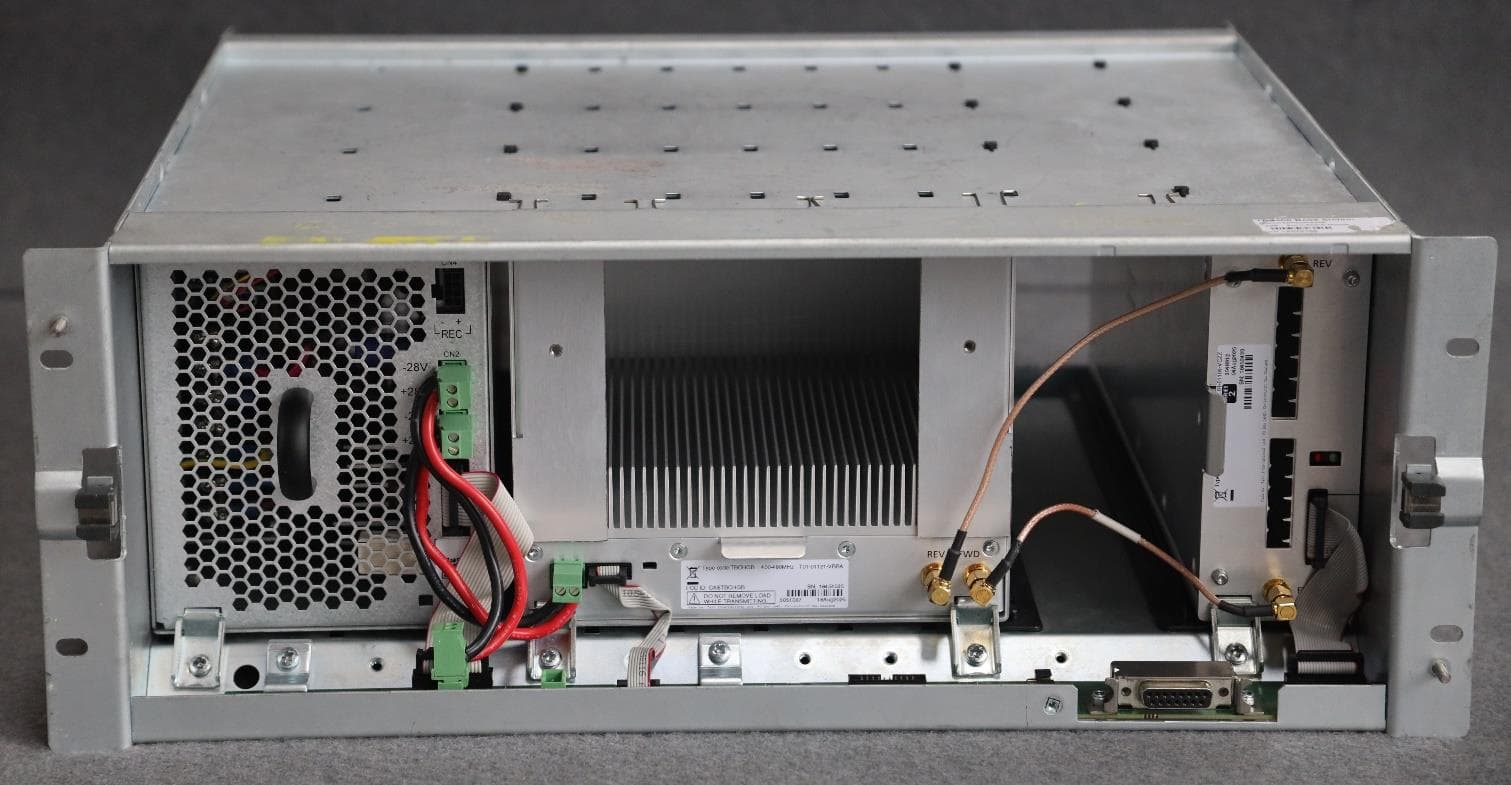
CASTBCHGB
May 12, 2026Base Station Transceiver
Equipment Class
TNB - Licensed Non-Broadcast Station Transmitter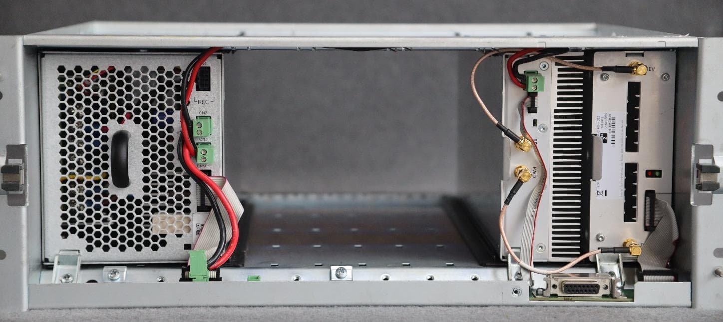
CASTBCHGA
May 12, 2026Base Station Transceiver
Equipment Class
TNB - Licensed Non-Broadcast Station Transmitter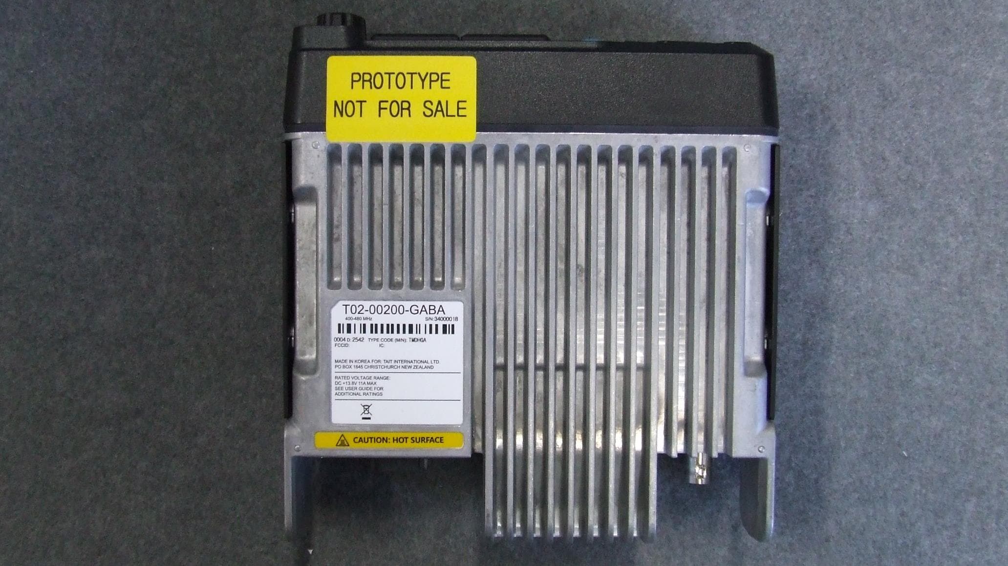
CASTMDHGA
Feb 04, 2026Mobile Transceiver
Equipment Class
TNB - Licensed Non-Broadcast Station Transmitter
CASTPJHGB
Jan 15, 2026Portable Transceiver
Equipment Class
TNF - Licensed Non-Broadcast Transmitter Held to Face
CASTPJHGA
Jan 15, 2026Portable Transceiver
Equipment Class
DSS - Part 15 Spread Spectrum Transmitter