CASTEL0064Base Station Paging Transmitter
Tait International Limited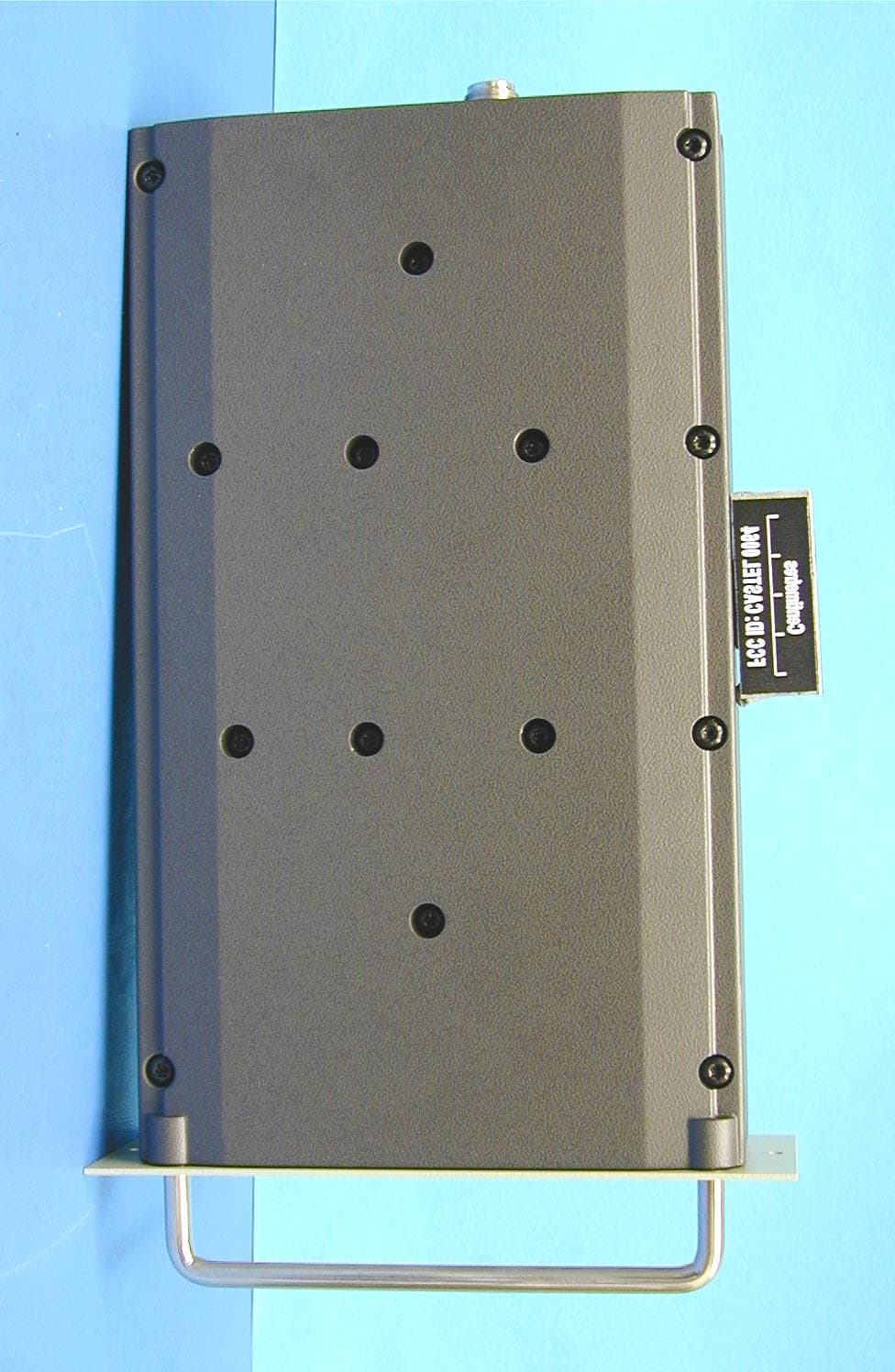
Click to zoom
Application Details
- Equipment Class
- TNB - Licensed Non-Broadcast Station Transmitter
- Date of Grant
- May 05, 2003
- Application Purpose
- Original Equipment
- Date of Application
- May 05, 2003
- Equipment Note
- Base Station Paging Transmitter
- Frequency Range
- 150.00000000 - 174.00000000
- Company
- Tait International Limited
- Country
- New Zealand
Documents & Files
Document Text
Text extracted from the exhibit documents filed with the FCC. Open a document above to read the original.
Users Manual
T800 Paging SystemsT800 Paging Systems A beginners guide to Tait’s paging offerings Tait Radio Systems Division Tait Electronics Ltd August 2002 T800 Paging Systems Page 2 of 2 1 Types of paging modulators/Transmitters Tait currently manufactures the following paging products: T800-30-0000 Differential Frequency Shift Keying, paging board suitable for use with 512 or 1200 baud Pocsag or speech T800-30-0002 As above but with external frequency reference. T800-32-0000 Low Speed Paging Modulator, suitable for use with 512, 1200 or 2400 baud Pocsag or 1600 baud FLEX. T800-32-0002 As above but with external frequency reference. T837-20-1020 Low Speed Paging Exciter, purpose built VHF exciter for use with 512, 1200 or 2400 baud Pocsag or 1600 baud FLEX. This is essentially a VHF exciter with the T800-32- 0000 paging modulator built into it. It does not have voice capability. T837-20-1021 As above but with external frequency reference. In addition to the above, you can order directly from the factory a T8xx-xx-1010 or T8xx-xx-1012 exciter or transmitter. These come with the T800-32-000x kit already fitted, and all required modifications done. These are suitable for UHF or 800/900 MHz paging requirements where we have not developed the Paging only exciter. Tait Electronics Ltd August 2002 T800 Paging Systems Page 3 of 3 2 High Stability Oscillator For wide area paging solutions, you will require some form of external frequency reference. The T801-20-0000 is a 10MHz OCXO reference with .001ppm stability and manually adjustable offsets up to 5ppm suitable for use with VHF wide area paging networks. It uses a single slot in a standard 5U T800 rack frame. The T800-28-0000 is a rack frame specifically designed for paging transmitters and includes slots for the T801-20-0000 reference, a Paging exciter and Power Amplifier, a T8x5 link receiver and a Power Supply. Tait Electronics Ltd August 2002 T800 Paging Systems Page 4 of 4 3 Modem / Delay board The T800-37-0000 is used for two reasons: 1. To add a digital delay to the paging signal. This is used to compensate for the propagation delay for outlying paging transmitters on a wide area paging network. 2. To decode the modem tones used on an analogue link from the paging encoder to the remote paging transmitter. The delay is adjustable from 0 – 5 msec in 3.35 μsec (1 km) steps. The asynchronous modem is compatible with V.23 or Bell 202 modem standards and either 512 or 1200 bps rates. The T800-37-0000 fits inside of a T837-20-102x paging exciter. Installation is as simple as connecting the supplied ribbon cable to the paging exciter and selecting the required delay and data polarity using solder links. The T800-37-0000 is not fitted into the link transmitter; a separate modem is needed to convert the paging encoder data to V.23 or Bell 202 tones. T800-35-0000 Tait Electronics Ltd August 2002 T800 Paging Systems Page 5 of 5 4 Typical Wide Area Paging options Tait only manufactures equipment used between the paging encoder and the paging receiver. We do not manufacture encoders or receivers, as this is an already developed market with many manufactures providing cheep and reliable products. At the encoder end, you would need something like a Zetron Model 15 Encoder, which has a RS232 output. For wide area paging you need to connect this to a V.23 or Bell 202 modem before connecting it to your UHF link transmitter. We can supply a Slimline T800 for this purpose. At the remote end, a T855 receiver is used to receive the signal from the central transmitter. This is then decoded by the T800- 37-0000 modem board, which also adds the required amount of delay to the signal. The T801-20-0000 is used to generate the reference frequency, with the required offset. The T837-20- 1021 then takes all of this to make the paging signal, which is fed to the PA and antenna equipment. And with any luck the subscriber has their pager turned on and receives the message. Paging Terminal Link TX Modem Paging encoder Link RX Modem Digital Delay Paging Exciter PA HSO Data entry
Users Manual
C1.6T837 General InformationM830P-00 01/07/00Copyright TEL 1.2Specifications 1.2.1Introduction The performance figures given are minimum figures, unless otherwise indicated, for equipment tuned with the maximum switching range and operating at standard room temperature (+22°C to +28°C) and standard test voltage (13.8V DC). Where applicable, the test methods used to obtain the following performance figures are those described in the EIA and ETS specifications. However, there are several parame- ters for which performance according to the Chinese specification GB/T 15938 is given. Refer to Section 1.2.6 for details of test standards. Details of test methods and the conditions which apply for Type Approval testing in all countries can be obtained from Tait Electronics Ltd. 1.2.2General Number Of Channels.. 128 (standard) 1 Supply Voltage: Operating Voltage .. 10.8 to 16V DC Standard Test Voltage.. 13.8V DC Polarity .. negative earth only Polarity Protection .. crowbar diode Line Keying Supply (if required) .. -50V DC Supply Current: Tr a n s m i t. . < 6 5 0 m A Standby- T837-2X-1020.. <150mA - T837-2X-1021.. <200mA Operating Temperature Range.. -30°C to +60°C Dimensions: Height .. 183mm Width .. 60mm Length .. 320mm Weight .. 2.1kg Time-Out Timer (optional) .. 0 to 5 minutes 2 adjustable in 10 sec- ond steps 1. Additional channels may be factory programmed. Contact your nearest Tait Dealer or Customer Service Organisation. 2. Adjustable from 0 to 10 minutes in PGM800Win version 2.12 and later. M830P-00T837 General InformationC1.7 Copyright TEL01/07/00 Tail Timer .. 0 to 5 seconds adjustable in 100ms 1 steps Tr a n s m i t K e y Ti m e : T837-20-102X.. <100ms T837-26-102X.. <30ms Transmit Lockout Timer.. 0 to 1 minute adjustable in 10 second steps 1.2.3RF Section Frequency Range .. 148-174MHz Modulation Type .. DFSK Frequency Increment: T837-20-102X.. 5 or 6.25kHz T837-26-102X.. 2.5 or 3.125kHz VCO Switching Range .. 8MHz Load Impedance.. 50 ohms Frequency Stability: T837-2X-1020.. ±1.0ppm, -20°C to +70°C ±2.0ppm, -30°C to +70°C T837-2X-1021.. ±1.5ppm, -30°C to +70°C External Reference Frequency.. 100kHz to 25.6MHz in 100kHz steps (T837-2X-1021) External Reference Amplitude.. 0 to +10dBm into 50Ω Adjacent Channel Power.. -75dBc (ETS) (4.5kHz deviation)-70dBc (GB/T 15938) Transmitter Side Band Noise: (no modulation, 15kHz bandwidth) At ±25kHz .. -95dBc At ±1MHz .. -105dBc Radiated Spurious Emissions: Transmit .. -36dBm to 1GHz -30dBm to 4GHz Standby .. -57dBm to 1GHz -47dBm to 4GHz 1. Adjustable in 20ms steps in PGM800Win version 2.12 and later. C1.8T837 General InformationM830P-00 01/07/00Copyright TEL Power Output.. 800mW ±200mW Transmit Keying Noise.. -70dBc (GB/T 15938) 1.2.4Low Speed Paging Modulator Accepted Protocols/Speeds: T837-20-102X.. POCSAG 512/1200 and FLEX 1600 T837-26-102X.. POCSAG 512/1200/2400 and FLEX 1600 Input Data Levels.. TTL Data Rise Time (10% - 90%): T837-20-102X.. <150μs (GB/T 15938) T837-26-102X.. <115μs 1.2.5Microcontroller Auxiliary Ports: Open Drain Type.. capable of sinking 2.25mA via 2k2Ω V ds max... 5V 1.2.6Test Standards Where applicable, this equipment is tested in accordance with the following standards. 1.2.6.1European Telecommunication Standard ETS 300 113 March 1996 Radio equipment and systems; land mobile service; technical characteristics and test conditions for radio equipment intended for the transmission of data (and speech) and having an antenna connector. 1.2.6.2Telecommunications Industry Association ANSI/TIA/EIA-603-1992 Land mobile FM or PM communications equipment measurement and performance standards. M830P-00T837 General InformationC1.9 Copyright TEL01/07/00 1.2.6.3Chinese Radio Regulatory Commission GB/T 15938 - 1995 General specification for equipment of radio paging systems.
Users Manual
Copyright TEL31/01/96 1T835/836/837 Installation 1.1Rack Mounting The T835 receiver, T836 transmitter and T837 exciter are designed for use in a standard 483mm rack frame using a Tait T800 Series guide which locates and mates the rear D-range connectors (refer to Figure 1.1, Figure 1.2 and Figure 1.3). A T800 Series guide is supplied with each unit. The guide is located in the rack frame with four screws, two at the rear and two at the front, and the T800 unit is secured into the guide with two front panel mounting screws. A rear mounted N-type connector is used for RF input on the T835 receiver and RF out- put on the T836 transmitter, while the exciter RF output is via the front panel SMC con- nector. All DC, audio and control connections are via the rear mounted D-range connector. An additional rear D-range connector (T800-03) is fitted when remote mul- tichannel operation, or additional control or low frequency lines are required. Figure 1.1 T800 Series Guide è Figure 1.2 T835/836 Chassis Connectors è Figure 1.3 T837 Chassis Connectors ç 31/01/96Copyright TEL 1.2Rack Wiring Wire the D-range connector as shown in Figure 1.4 or Figure 1.5. Ensure that the cables are not subjected to any stresses due to tight bends or incorrect lengths. The RF coaxial cable to the N-type connector should be free from acute bends or twists. If access to the rear of the rack frame is restricted, the cable should be long enough to permit full withdrawal of the chassis from the guide. Figure 1.4 T835 D-Range Wiring - Rear View Figure 1.5 T836/837 D-Range Wiring - Rear View Line I/P1 Speaker Audio 2 Audio 1 RSSI Line I/P4 Line I/P3 Line I/P2 Short together for normal operation Gate O/P Common 1 N.O. 1 Relay +Ve Gnd Pin 15 Pin 8 Pin 1Pin 9 Short together for normal operation Line I/P1 CTCSS Audio 1 Audio 2 Tx Enable Line I/P4 Line I/P3 Line I/P2 Short together for normal operation Opto Key + Opto Key - +13.8V Gnd Pin 15 Pin 8 Pin 1Pin 9 Tx Key Note: Audio 1 formerly Line 1 Audio 2 formerly Line 2 Copyright TEL31/01/96 1.3Power Supply If a power supply other than an appropriate Tait model is used, ensure that it is capable of providing enough current to drive the T800 system and is also free from excessive ripple or noise. The system should be protected by the use of appropriately rated fuses in the power supply. Note:It is particularly important when the prime power source is a battery that fuses be employed in all supply lines. 1.4Reverse Polarity Protection A shunt diode is fitted to all T835 receivers, T836 transmitters and T837 exciters for pro- tection against connection to a power supply of incorrect polarity. Note:A fuse must be fitted in the power supply line for the diode to provide effec- tive protection.
Users Manual
D1.6T838/839 General InformationM830P-00 01/07/00Copyright TEL 1.2Specifications 1.2.1Introduction The performance figures given are minimum figures, unless otherwise indicated, for equipment operating at standard room temperature (+22°C to +28°C) and standard test voltage (13.8V DC). Where applicable, the test methods used to obtain the following performance figures are those described in the ETS and Chinese GB/T 15938 specifications. Refer to Section 1.2.3 for details of test standards. Details of test methods and the conditions which apply for Type Approval testing in all countries can be obtained from Tait Electronics Ltd. 1.2.2General Power Output: T838- Rated Power .. 50W - Range Of Adjustment .. 10 to 60W (typical) T839- Rated Power .. 100W - Range Of Adjustment .. 20 to 120W (typical) Input Power.. 600mW to 1W Duty Cycle Rating: T838.. 50W continuous to +60°C T839.. 100W continuous to +60°C Intermodulation .. -70dBc or -40dBi 1 with 25dB isolation (PA with output isolator) & interfering signal of -30dBc Mismatch Capability: Ruggedness .. refer to your nearest Tait Dealer or Customer Service Organisation Stability .. 5:1 VSWR (all phase angles) Supply Voltage: Operating Voltage .. 10.8 to 16V DC Standard Test Voltage .. 13.8V DC Polarity.. negative earth only Polarity Protection .. crowbar diode 1. dBi denotes the level of the intermodulation product relative to the interfering signal. M830P-00T838/839 General InformationD1.7 Copyright TEL01/07/00 Supply Current: Standby .. 50mA Transmit- T838.. 11A (9A typical @ 156MHz) - T839.. 19A (15A typical @ 156MHz) Spurious Emissions: Conducted- Transmit .. -36dBm to 1GHz -30dBm to 4GHz - Standby .. -57dBm to 1GHz -47dBm to 4GHz Radiated- Transmit .. -36dBm to 1GHz -30dBm to 4GHz - Standby .. -57dBm to 1GHz -47dBm to 4GHz Operating Temperature Range.. -30°C to +60°C Dimensions: Height .. 183mm Width- T838.. 60mm - T839.. 120mm Length.. 340mm We i g h t : T838.. 3.2kg T839.. 3.4kg 1.2.3Test Standards Where applicable, this equipment is tested in accordance with the following standards. 1.2.3.1European Telecommunication Standard ETS 300 086 January 1991 Radio equipment and systems; land mobile service; technical characteristics and test conditions for radio equipment with an internal or external RF connector intended pri- marily for analogue speech. ETS 300 113 March 1996 Radio equipment and systems; land mobile service; technical characteristics and test conditions for radio equipment intended for the transmission of data (and speech) and having an antenna connector. ETS 300 219 October 1993 Radio equipment and systems; land mobile service; technical characteristics and test conditions for radio equipment transmitting signals to initiate a specific response in the receiver. D1.8T838/839 General InformationM830P-00 01/07/00Copyright TEL ETS 300 279 February 1996 Radio equipment and systems; electromagnetic compatibility (EMC) standard for pri- vate land mobile radio (PMR) and ancillary equipment (speech and/or non-speech). 1.2.3.2DTI CEPT Recommendation T/R-24-01 Annex I: 1988 Technical characteristics and test conditions for radio equipment in the land mobile service intended primarily for analogue speech. Annex II: 1988 Technical characteristics of radio equipment in the land mobile service with regard to quality and stability of transmission. 1.2.3.3Telecommunications Industry Association ANSI/TIA/EIA-603-1992 Land mobile FM or PM communications equipment measurement and performance standards. 1.2.3.4Chinese Radio Regulatory Commission GB/T 15938 - 1995 General specification for equipment of radio paging systems.
Users Manual
Copyright TEL31/01/96 2T838 Installation 2.1Rack Mounting The T838 50W PA is designed for use in a standard 483mm rack frame using the sup- porting guide rails supplied with the units (refer to Figure 2.1). The lower guide rail is located in the rack frame with three screws, two at the rear and one at the front. The short upper guide rail is located with just one screw. The PA is secured into the guide with two front panel mounting screws. The RF input via the front panel SMC connector should be connected to an adjacent T837 exciter. The RF output is via the rear N-type connector, whilst all DC, audio and control connections are via the D-range connector. The guide rails will allow the PA to be latched in the extended position (refer to Figure 2.3). Caution:If continuous operation of the T838 is required, the rack module posi- tion immediately adjacent to the finned heatsink should be left vacant. Adequate airflow over the fins should be maintained at all times. Figure 2.1 T838 Guide è Figure 2.2 Chassis Connectors ç 31/01/96Copyright TEL Figure 2.3 Latched Position 2.2Rack Wiring Wire the D-range connector as shown in Figure 2.4. Ensure that the cables are not sub- jected to any stresses due to tight bends or incorrect lengths. The RF coaxial cable to the N-type connector should be free from acute bends or twists. If access to the rear of the rack frame is restricted, the cable should be long enough to permit full withdrawal of the chassis from the guide. Figure 2.4 D-Range Wiring - Rear View Reverse Power Metering Forward Power Metering Reverse Power Alarm Forward Power Alarm Tx Key +13.8V Gnd Pin 15 Pin 8 Pin 1Pin 9 Copyright TEL31/01/96 2.3Power Supply If a power supply other than an appropriate Tait model is used, ensure that it is capable of providing enough current to drive the T800 system and is also free from excessive ripple or noise.
Users Manual
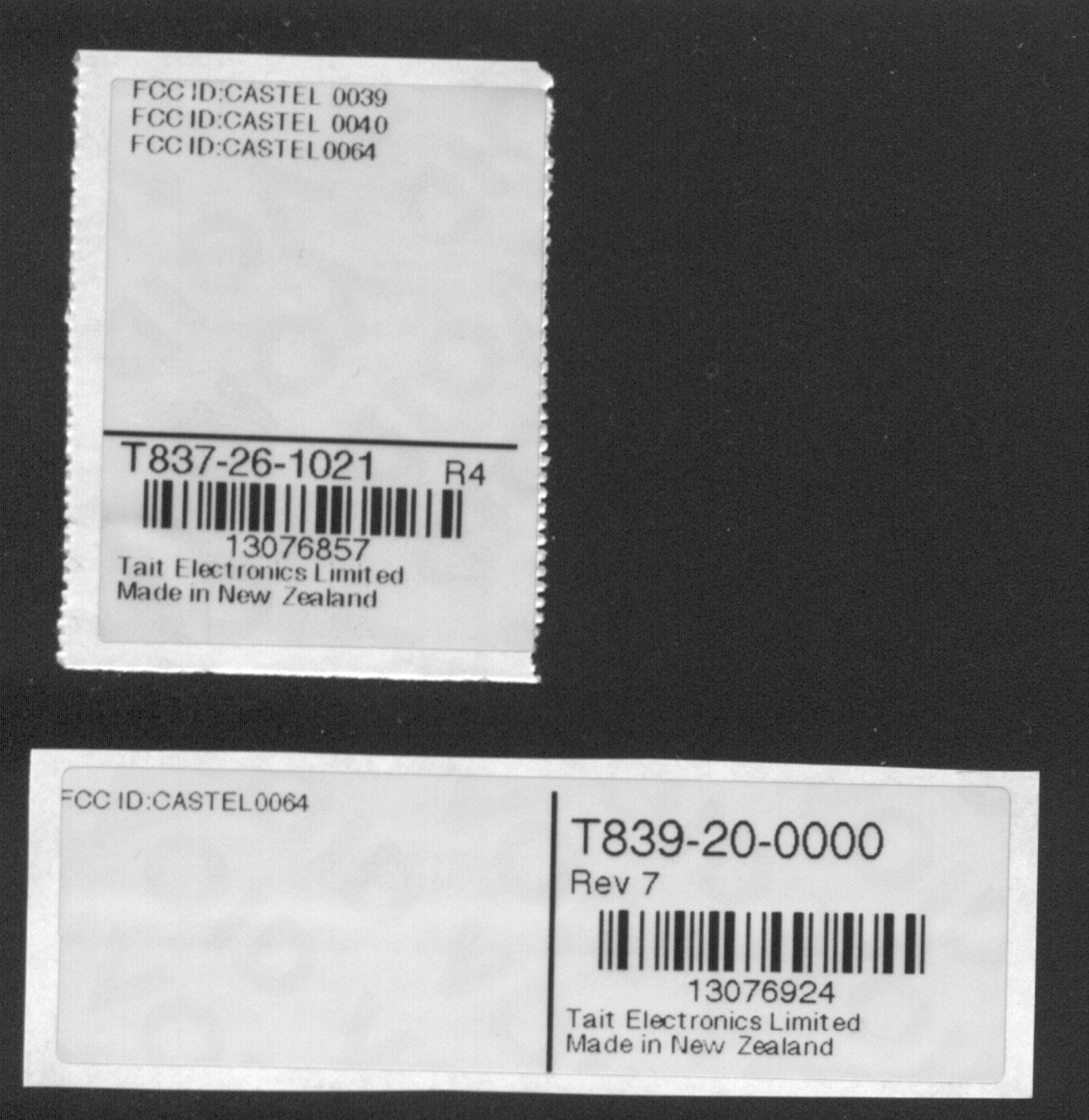
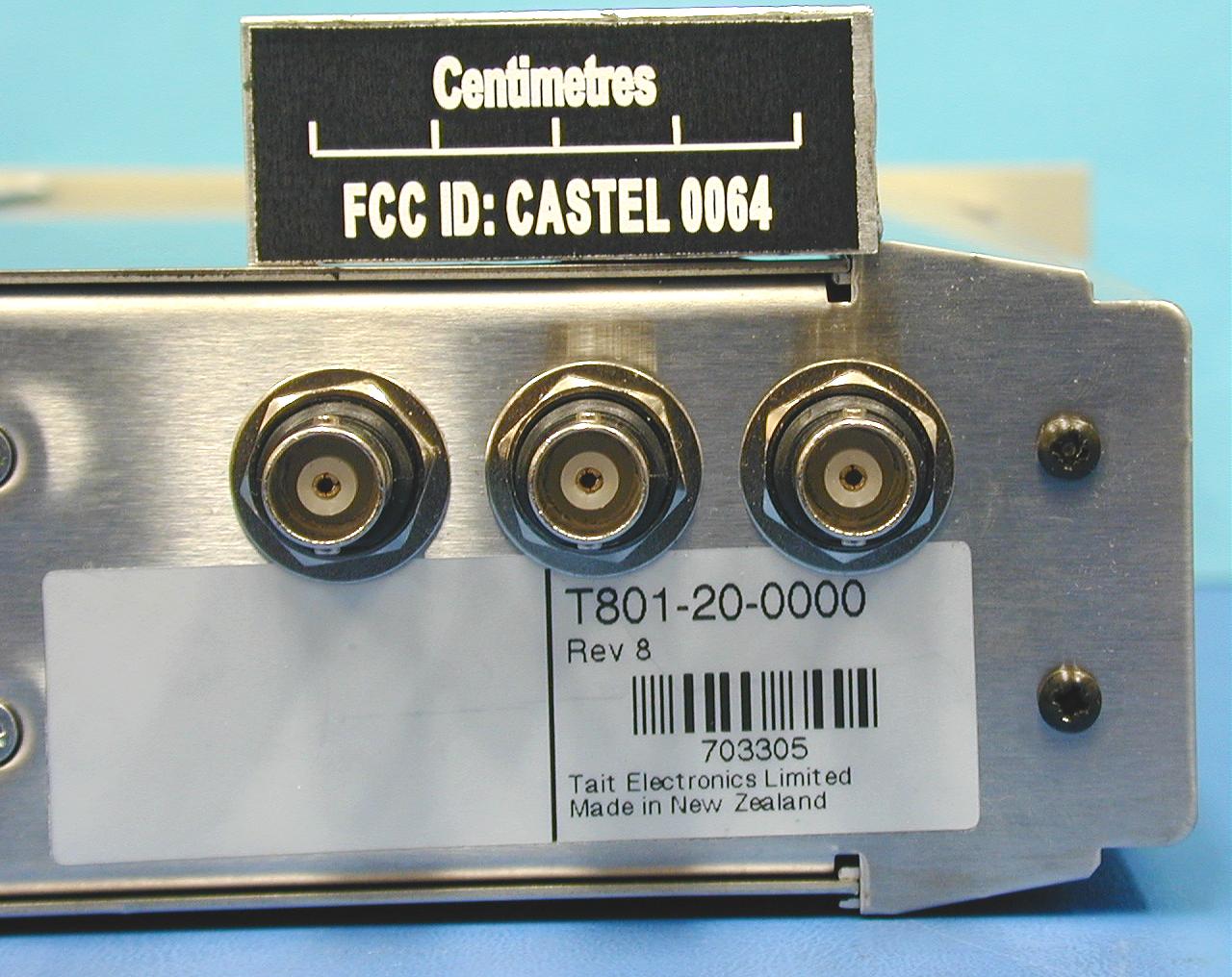
M830P-00GeneralA1.1 Copyright TEL01/07/03 1General 1.1Additional Technical Information If you have any questions about this manual or the equipment it describes, please con- tact your nearest Tait Dealer or Customer Service Organisation. If necessary, you can get additional technical help from Customer Support, Tait Electronics Ltd, Christchurch, New Zealand (full contact details are on page 2). When requesting information, please quote either the manual product code (e.g. M830P-00-1TA), or the equipment product code and serial number which are printed on a label on the back of the product (as shown in Figure 1.1). Figure 1.1 Typical Product Code & Serial Number Labels If you require information about a particular PCB, please quote the full PCB internal part number (IPN) which is screen printed onto the top side of the board (refer to the appropriate PCB Information section in this manual for more details). 1.2Caution: CMOS Devices This equipment contains CMOS Devices which are susceptible to damage from static charges. Care when handling these devices is essential. For correct handling proce- dures refer to the manufacturers' data books, e.g. Philips data books covering CMOS devices, or Motorola CMOS data books, Section 5 'Handling', etc. An anti-static bench kit (refer to Figure 1.2) is available from Tait Electronics Ltd under the following product codes: • KS0001 - 1 conductive rubber bench mat - 1 earth lead to connect the mat to ground •KS0004- 1 wrist strap. this area used for regional Type Approval information product code serial number T835-10-0000Rev 1 900000 Tait Electronics Limited Made in New Zealand T838-10-0000 Rev 1 900000 Tait Electronics Limited Made in New Zealand A1.2GeneralM830P-00 01/07/03Copyright TEL Figure 1.2 Typical Anti-static Bench Set-up 1.3Caution: Aerial Load The equipment has been designed to operate safely under a wide range of aerial loading conditions. However, we strongly recommend that the transmitter should always be operated with a suitable load to prevent damage to the transmitter output power stage. 1.4Caution: Beryllium Oxide & Power Transistors The RF power transistors in current use all contain some beryllium oxide. This sub- stance, while perfectly harmless in its normal solid form, can become a severe health hazard when it has been reduced to dust. For this reason the RF power transistors should not be broken open, mutilated, filed, machined, or physically damaged in any way that can produce dust particles. 1.5USA Installations: RF Exposure Compliance, Control Guidelines and Operating Instructions All radio transmitter installations must comply with the FCC environmental rules (refer to CFR 47 Chapter 1, sub-part I). In addition, the FCC requires the following safety information to be provided by the radio manufacturer: To control exposure to yourself and others and ensure compliance with the gen- eral/uncontrolled and occupational/controlled environment exposure limits always adhere to the following procedures. to building earth (not mains earth) conductive wrist strap conductive rubber bench mat M830P-00GeneralA1.3 Copyright TEL01/07/03 Guidelines: • User awareness instructions must accompany this device when transferred to other users. • Do not use this device if the operational requirements described herein are not met. Instructions: • Transmit only when people near the antenna are at least the recommended minimum distance away, as shown in Ta b l e 1 . 1, from a properly installed, according to installation instructions, externally-mounted antenna. Note:Ta b l e 1 . 1 lists the recommended minimum distance for bystanders in an uncontrolled environment from transmitting types of antennas at fre- quencies in the range 138-174MHz and several different ranges of rated radio power. Table 1.1 Rated Power and Recommended Distance Rated Power of TransmitterRecommended Minimum Distance from Transmitting Antenna a a.These distances are calculated based on a 6dBi gain collinear antenna as might be used in a typical installation. For other powers and antenna types, consult the sup- plier. 513cm 50133cm 100 watts265cm A1.4GeneralM830P-00 01/07/03Copyright TEL
Users Manual
M830P-00GeneralA1.1 Copyright TEL01/07/03 1General 1.1Additional Technical Information If you have any questions about this manual or the equipment it describes, please con- tact your nearest Tait Dealer or Customer Service Organisation. If necessary, you can get additional technical help from Customer Support, Tait Electronics Ltd, Christchurch, New Zealand (full contact details are on page 2). When requesting information, please quote either the manual product code (e.g. M830P-00-1TA), or the equipment product code and serial number which are printed on a label on the back of the product (as shown in Figure 1.1). Figure 1.1 Typical Product Code & Serial Number Labels If you require information about a particular PCB, please quote the full PCB internal part number (IPN) which is screen printed onto the top side of the board (refer to the appropriate PCB Information section in this manual for more details). 1.2Caution: CMOS Devices This equipment contains CMOS Devices which are susceptible to damage from static charges. Care when handling these devices is essential. For correct handling proce- dures refer to the manufacturers' data books, e.g. Philips data books covering CMOS devices, or Motorola CMOS data books, Section 5 'Handling', etc. An anti-static bench kit (refer to Figure 1.2) is available from Tait Electronics Ltd under the following product codes: • KS0001 - 1 conductive rubber bench mat - 1 earth lead to connect the mat to ground •KS0004- 1 wrist strap. this area used for regional Type Approval information product code serial number T835-10-0000Rev 1 900000 Tait Electronics Limited Made in New Zealand T838-10-0000 Rev 1 900000 Tait Electronics Limited Made in New Zealand A1.2GeneralM830P-00 01/07/03Copyright TEL Figure 1.2 Typical Anti-static Bench Set-up 1.3Caution: Aerial Load The equipment has been designed to operate safely under a wide range of aerial loading conditions. However, we strongly recommend that the transmitter should always be operated with a suitable load to prevent damage to the transmitter output power stage. 1.4Caution: Beryllium Oxide & Power Transistors The RF power transistors in current use all contain some beryllium oxide. This sub- stance, while perfectly harmless in its normal solid form, can become a severe health hazard when it has been reduced to dust. For this reason the RF power transistors should not be broken open, mutilated, filed, machined, or physically damaged in any way that can produce dust particles. 1.5USA Installations: RF Exposure Compliance, Control Guidelines and Operating Instructions All radio transmitter installations must comply with the FCC environmental rules (refer to CFR 47 Chapter 1, sub-part I). In addition, the FCC requires the following safety information to be provided by the radio manufacturer: To control exposure to yourself and others and ensure compliance with the gen- eral/uncontrolled and occupational/controlled environment exposure limits always adhere to the following procedures. to building earth (not mains earth) conductive wrist strap conductive rubber bench mat M830P-00GeneralA1.3 Copyright TEL01/07/03 Guidelines: • User awareness instructions must accompany this device when transferred to other users. • Do not use this device if the operational requirements described herein are not met. Instructions: • Transmit only when people near the antenna are at least the recommended minimum distance away, as shown in Ta b l e 1 . 1, from a properly installed, according to installation instructions, externally-mounted antenna. Note:Ta b l e 1 . 1 lists the recommended minimum distance for bystanders in an uncontrolled environment from transmitting types of antennas at fre- quencies in the range 138-174MHz and several different ranges of rated radio power. Table 1.1 Rated Power and Recommended Distance Rated Power of TransmitterRecommended Minimum Distance from Transmitting Antenna a a.These distances are calculated based on a 6dBi gain collinear antenna as might be used in a typical installation. For other powers and antenna types, consult the sup- plier. 513cm 50133cm 100 watts265cm A1.4GeneralM830P-00 01/07/03Copyright TEL
Users Manual
M830P-00GeneralA1.1 Copyright TEL01/07/03 1General 1.1Additional Technical Information If you have any questions about this manual or the equipment it describes, please con- tact your nearest Tait Dealer or Customer Service Organisation. If necessary, you can get additional technical help from Customer Support, Tait Electronics Ltd, Christchurch, New Zealand (full contact details are on page 2). When requesting information, please quote either the manual product code (e.g. M830P-00-1TA), or the equipment product code and serial number which are printed on a label on the back of the product (as shown in Figure 1.1). Figure 1.1 Typical Product Code & Serial Number Labels If you require information about a particular PCB, please quote the full PCB internal part number (IPN) which is screen printed onto the top side of the board (refer to the appropriate PCB Information section in this manual for more details). 1.2Caution: CMOS Devices This equipment contains CMOS Devices which are susceptible to damage from static charges. Care when handling these devices is essential. For correct handling procedures refer to the manufacturers' data books, e.g. Philips data books covering CMOS devices, or Motorola CMOS data books, Section 5 'Handling', etc. An anti-static bench kit (refer to Figure 1.2) is available from Tait Electronics Ltd under the following product codes: • KS0001 - 1 conductive rubber bench mat - 1 earth lead to connect the mat to ground •KS0004- 1 wrist strap. this area used for regional Type Approval information product code serial number T835-10-0000Rev 1 900000 Tait Electronics Limited Made in New Zealand T838-10-0000 Rev 1 900000 Tait Electronics Limited Made in New Zealand A1.2GeneralM830P-00 01/07/03Copyright TEL Figure 1.2 Typical Anti-static Bench Set-up 1.3Caution: Aerial Load The equipment has been designed to operate safely under a wide range of aerial loading conditions. However, we strongly recommend that the transmitter should always be operated with a suitable load to prevent damage to the transmitter output power stage. 1.4Caution: Beryllium Oxide & Power Transistors The RF power transistors in current use all contain some beryllium oxide. This sub- stance, while perfectly harmless in its normal solid form, can become a severe health hazard when it has been reduced to dust. For this reason the RF power transistors should not be broken open, mutilated, filed, machined, or physically damaged in any way that can produce dust particles. 1.5USA Installations: RF Exposure Compliance, Control Guidelines and Operating Instructions All radio transmitter installations must comply with the FCC environmental rules (refer to CFR 47 Chapter 1, sub-part I). In addition, the FCC requires the following safety information to be provided by the radio manufacturer: To control exposure to yourself and others and ensure compliance with the gen- eral/uncontrolled and occupational/controlled environment exposure limits always adhere to the following procedures. to building earth (not mains earth) conductive wrist strap conductive rubber bench mat M830P-00GeneralA1.3 Copyright TEL01/07/03 Guidelines: • User awareness instructions must accompany this device when transferred to other users. • Do not use this device if the operational requirements described herein are not met. Instructions: • Transmit only when people near the antenna are at least the recommended minimum distance away, as shown in Ta b l e 1 . 1, from a properly installed, according to installation instructions, externally-mounted antenna. Note:Ta b l e 1 . 1 lists the recommended minimum distance for bystanders in an uncontrolled environment from transmitting types of antennas at fre- quencies in the range 138-174MHz and several different ranges of rated radio power. Table 1.1 Rated Power and Recommended Distance FCC Conditions of Use Output is conducted. The antenna(s) used for this transmitter must be fixed- mounted on outdoor permanent structures with a separation distance of at least 2.66 meters from all persons during normal operation. The peak conducted out- put power at each antenna terminal must not exceed 100W and the antenna gain must not exceed 6dBi. Users and installers must be provided with appropriate antenna installation instructions and transmitter operating conditions, including antenna co-location requirements of §1.1307(b)(3) for satisfying RF exposure com- pliance. Base Station Paging Transmitter can be operated with or without high sta- bility oscillator. Rated Power of TransmitterRecommended Minimum Distance from Transmitting Antenna 513cm 50133cm 100 watts266cm A1.4GeneralM830P-00 01/07/03Copyright TEL
Users Manual
M830P-00GeneralA1.1 Copyright TEL01/07/03 1General 1.1Additional Technical Information If you have any questions about this manual or the equipment it describes, please con- tact your nearest Tait Dealer or Customer Service Organisation. If necessary, you can get additional technical help from Customer Support, Tait Electronics Ltd, Christchurch, New Zealand (full contact details are on page 2). When requesting information, please quote either the manual product code (e.g. M830P-00-1TA), or the equipment product code and serial number which are printed on a label on the back of the product (as shown in Figure 1.1). Figure 1.1 Typical Product Code & Serial Number Labels If you require information about a particular PCB, please quote the full PCB internal part number (IPN) which is screen printed onto the top side of the board (refer to the appropriate PCB Information …
Text truncated - open the document above for the full version.
Contact Information
Applicant
Linda White(Standards and Regulatory Manager)
Technical Specifications
| # | Rule Parts | Frequency Range | Power Output | Emission | Tolerance |
|---|---|---|---|---|---|
| 8 | 22,9 | 150 MHz - 174 MHz | 100 W | 13K2F1D | 0.01 ppm |
Other Applications from Tait International Limited
CASTBCHGB
May 12, 2026Base Station Transceiver
Equipment Class
TNB - Licensed Non-Broadcast Station Transmitter
CASTBCHGA
May 12, 2026Base Station Transceiver
Equipment Class
TNB - Licensed Non-Broadcast Station Transmitter
CASTMDHGA
Feb 04, 2026Mobile Transceiver
Equipment Class
TNB - Licensed Non-Broadcast Station Transmitter
CASTPJHGB
Jan 15, 2026Portable Transceiver
Equipment Class
TNF - Licensed Non-Broadcast Transmitter Held to Face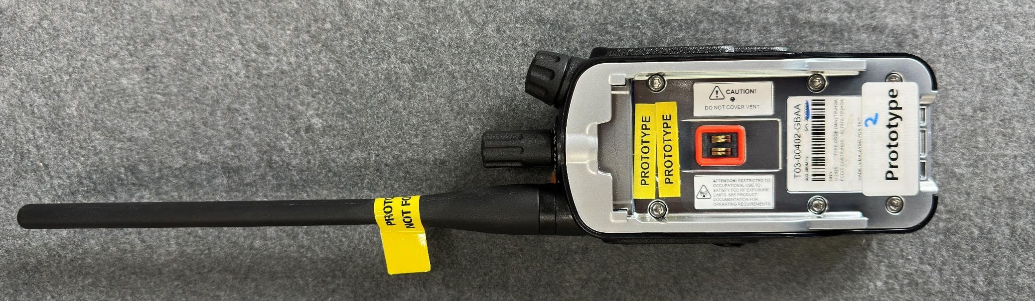
CASTPJHGA
Jan 15, 2026Portable Transceiver
Equipment Class
DSS - Part 15 Spread Spectrum Transmitter