CB2120NHL3Universal Garage Door Opener/Home Link
Johnson Controls Interiors L.L.C.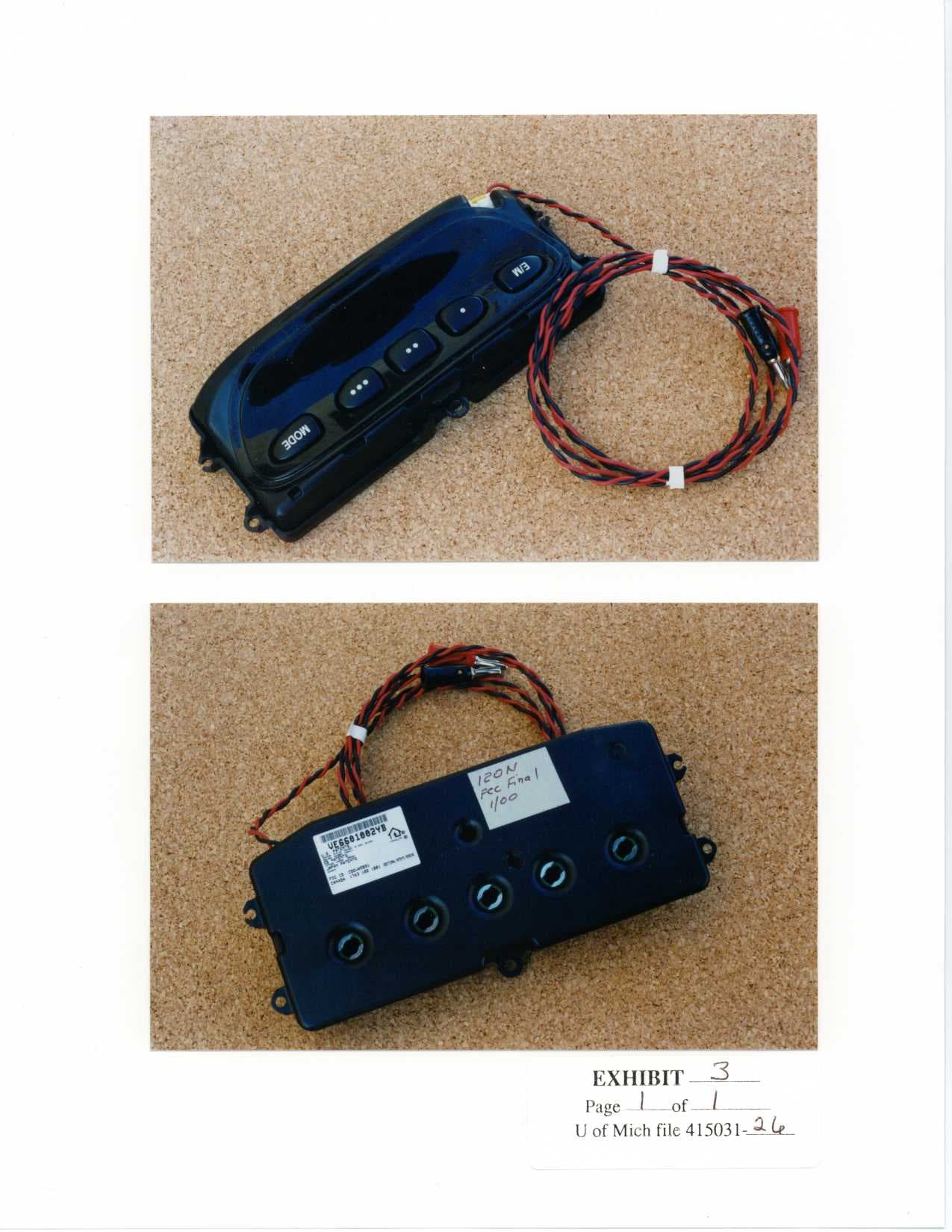
Click to zoom
Application Details
- Equipment Class
- DSC - Part 15 Security/Remote Control Transmitter
- Date of Grant
- Feb 21, 2000
- Application Purpose
- Original Equipment
- Date of Application
- Feb 07, 2000
- Equipment Note
- Universal Garage Door Opener/Home Link
- Frequency Range
- 410.00000000 - 418.00000000
- Country
- United States
Documents & Files
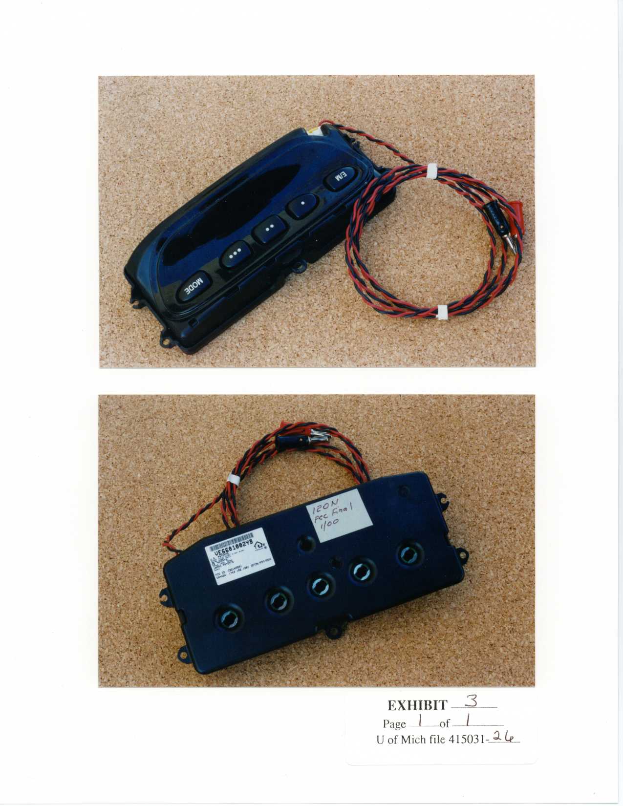
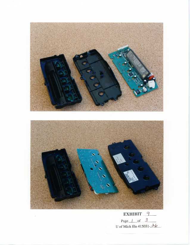
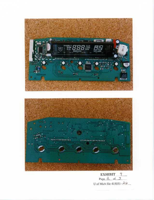
Document Text
Text extracted from the exhibit documents filed with the FCC. Open a document above to read the original.
Operational Description
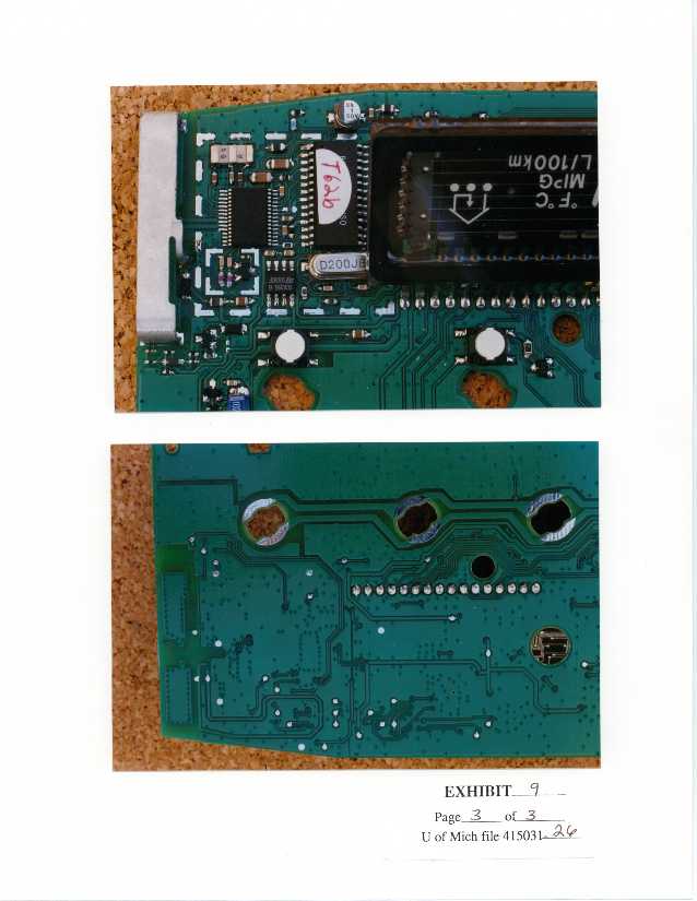
120N Compass/Temperature/Trip/Homelink Module Description of Operation The 120N module consists of two basic sections. The Compass/Temperature/Trip (CTT) section, and the Homelink section. The CTT section provides data to the user via a Vacuum Fluorescent Display (VFD) display. There are switches on board, two of which allow the user to change CTT modes operation, and three others which allow the user to select Homelink operation. The CTT micro-processor then powers up the Homelink section, and communicates to the Homelink microprocessor which channel has been selected. The Homelink transmitter is a radio frequency transceiver device whose primary function is to determine both frequency and bit code format of typical garage door remote control devices and identically re-transmit them to the original garage door opener receiver. The on-board microcontroller maintains the operational frequency band as 288Mhz to 418Mhz excluding forbidden bands of 240MHz to 285MHz, 322MHz to 335.4MHz and 399.9MHz to 410 MHz. The “training” operation is performed by scanning the legal frequencies with a single conversion superheterodyne receiver, looking for valid garage door opener bit code formats. In addition to being frequency and data format adaptive the Homelink transmitter is also RF amplitude adaptive. During the training sequence, the duty factor of the incoming bit code format is evaluated by the microcontroller determining the greatest amount of on- time in a 100 mS window. The duty factor is then used to mathematically adjust the output power in a range of 80% (1.9dB) to an upper limit of 30% (10.5dB) duty cycle. A 9 bit attenuator is adjusted by a closed loop power control algorithm in the microcontroller. After the training sequence the frequency bit code format and attenuator setting is stored in non-volatile memory (NVM) and retrieved on subsequent power ups. The VCO is set on the desired RF carrier frequency stored in NVM. The antenna is fine tuned by sweeping twice around the expected tuning point. The voltage controlled oscillator(VCO) is then modulated with the appropriate bit code information from the NVM.
Contact Information
Applicant
Rick Markiewicz(Electronics Engineering Manager)
Technical Contact
University of Michigan/EECSValdis V Liepa
[email protected]734-483-4211
1301 Beal Avenue · Ann Arbor, Michigan · United States
Non-Technical Contact
University of Michigan/EECSValdis V Liepa
[email protected]734-483-4211
Test Firm
University of MichiganValdis Liepa
Technical Specifications
| # | Rule Parts | Frequency Range | Power Output | Tolerance |
|---|---|---|---|---|
| 3 | 15C | 410 MHz - 418 MHz | - | % |
Other Applications from Johnson Controls Interiors L.L.C.

CB2-BLUE15M-TCU
Mar 20, 2014Automotive Telematics Module with Handsfree Bluetooth
Equipment Class
DSS - Part 15 Spread Spectrum Transmitter
CB2-BLUE15M
Jan 19, 2014Bluetooth Telematics Device
Equipment Class
DSS - Part 15 Spread Spectrum Transmitter
CB262932
Jul 15, 2013Automotive Electronics Infotainment Head Unit with Bluetooth and WLAN
Equipment Class
DTS - Digital Transmission System
CB2775AHL5
Apr 29, 2013Universal Garage Door Opener w/ FHSS TX
Equipment Class
DSR - Part 15 Remote Control/Security Device Transceiver
CB2440AHL5
Feb 24, 2013Universal Garage Door TX w/ FHSS TX
Equipment Class
DSS - Part 15 Spread Spectrum Transmitter