CB2BLUEC05Automotive Bluetooth Hands-Free Interface
Johnson Controls Interiors L.L.C.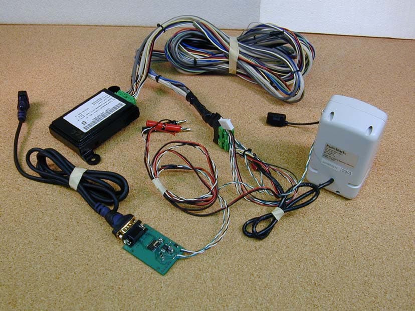
Click to zoom
Application Details
- Equipment Class
- DSS - Part 15 Spread Spectrum Transmitter
- Date of Grant
- Jul 01, 2004
- Application Purpose
- Original Equipment
- Date of Application
- Jul 01, 2004
- Equipment Note
- Automotive Bluetooth Hands-Free Interface
- Frequency Range
- 2412.00000000 - 2483.50000000
- Country
- United States
Documents & Files
Document Text
Text extracted from the exhibit documents filed with the FCC. Open a document above to read the original.
Users Manual
Re: Certification for JCI Bluetooth Transmitter Model: CB2BLUEC05 FCC ID: CB2BLUEC05 IC: 279B-BLUEC05 USER'S MANUAL INFORMATION (PRELIMINARY) The User's Manual is in preparation. The following material will be contained in the manual: FCC ID: CB2BLUEC05 IC: 279B-BLUEC05 This device complies with Part 15 of the FCC Rules and with RSS-210 of Industry Canada. Operation is subject to the following two conditions: (1) This device may not cause harmful interference, and (2) This device must accept any interference received, including interference that may cause undesired operation. WARNING: Changes or modifications not expressively approved by the party responsible for compliance could void the user's authority to operate the equipment. The term “IC:” before the radio certification number only signifies that Industry Canada technical specifications were met.
Attestation Statements
American TCB 6731 Whittier Ave. McLean, VA 22101 Acknowledgement of IC Listing Requirements By signing this document, we acknowledge that any information specified on the ATCB Application and Agreement Form for Industry Canada Certification Services provided with this application may be provided to Industry Canada. We acknowledge that this information may be posted in the Radio Equipment List (REL) on the Department's Web Site. Additionally, we understand that we must inform ATCB of any changes to the information submitted. We further acknowledge that the Certified product shall not be distributed, leased, or offered for sale in Canada prior to its listing on the Industry Canada Radio Equipment List (REL). We are aware that we may verify the status of this listing at the following web address: http://strategis.ic.gc.ca/cgi-bin/sc_mrksv/spectrum/reltelSearch/search.pl?lang=e&db=rel Dated this ____1___________day of ____July_______, 2004___. By: ____ ______________________ __Jeremy P. Bos___ (Signature) (Print name) Title: ____________Lead EMC Test Engineer______________ email: [email protected]________ On behalf of: ___Johnson Controls Interiors, L.L.C._______ (Company Name) Telephone: _____616-394-6076________ Attn: Director of Certification Authority to Act as Agent I appoint Valdis V. Liepa to act as our agent in the preparation of this application for equipment certification. I certify that submitted documents properly describe the device or system for which equipment certification is sought. I also certify that each unit manufactured, imported or marketed, as defined in Industry Canada’s regulations will have affixed to it a label identical to that submitted for approval with this application. For instances where our authorized agent signs the application for certification on our behalf, I acknowledge that all responsibility for complying with the terms and conditions for Certification, as specified by American TCB, still resides with ___( applicant name and address)___. Dated this _____1_______day of ____July____, 2004___. Agency Agreement Expiration Date: (Typically 8-12 months) By: _____ _____ _____Jeremy P. Bos______ (Signature) (Print name) Title: ______Lead EMC Test Engineer________ On behalf of: ____Johnson Controls Interior, LLC______ (Company Name) Telephone: ____616-394-6076_______________ Re: Certification for JCI Bluetooth Transmitter Model: CB2BLUEC05 FCC ID: CB2BLUEC05 IC: 279B-BLUEC05 POWER OF ATTORNEY A letter granting Valdis V. Liepa the Power of Attorney is on file and can be provided when so requested. Re: Certification for JCI Bluetooth Transmitter Model: CB2BLUEC05 FCC ID: CB2BLUEC05 IC: 279B-BLUEC05 REQUEST FOR CONFIDENTIALITY Pursuant to 47 CRF 0.459, JCI Bluetooth requests that a part of the subject application be held confidential. This comprises Exhibits (5) Schematics (10) Parts List (Part of Exhibit only) JCI Bluetooth has spent substantial effort in developing this product and it is one of the first of its kind in industry. Having the subject information easily available to "competition" would negate the advantage they have achieved by developing this product. Not protecting the details of the design will result in financial hardship. If there are any questions regarding this request, please contact me at the above address or call 734-483-4211, fax 734-647-2106 or e-mail [email protected]. Sincerely, Valdis V. Liepa Research Scientist University of Michigan June 29, 2004 Re: Certification for JCI Bluetooth Transmitter Model: CB2BLUEC05 FCC ID: CB2BLUEC05 IC: 279B-BLUEC05 STATEMENT OF MODIFICATIONS There were no modifications made to the DUT by this test laboratory. (Also see Section 3.1 of the attached Test Report). _____________________ Valdis V. Liepa Research Scientist Re: Certification for JCI Bluetooth Transmitter Model: CB2BLUEC05 FCC ID: CB2BLUEC05 IC: 279B-BLUEC05 GENERAL PRODUCT INFORMATION The device, for which certification is pursued, has been designed by: Johnson Controls Interiors L.L.C. One Prince Center Holland, MI 49423 Jeremy Bos Tel: (616) 394-6076 Fax: (616) 394-6100 It will be manufactured by: Johnson Controls Interiors L.L.C. One Prince Center Holland, MI 49423 Jeremy Bos Tel: (616) 394-6076 Fax: (616) 394-6100 Canadian Contact: Johnson Controls Lakeshore Plant 477 Jutras Dr. South Tecumseh, ON N8N 5C4 Jim Komar [email protected] (519) 727-2341 (519) 727-4750
Block Diagram
MEMORY BUS JTAG WDOG RESET GPIO OSC AN[0:3] USB I 2 S SCIF0 SCIF1 AC97 SCIF2 CAN 2.0 SPI RENESAS SH7760 SDRAM 16MB or 32MB FLASH 16MB or 32MB ENET/ JTAG I/F CONN. ADDRESS BUS DATA BUS XTAL 16.666 MHz Debug TX/ Icon 1 Out 1 1 5 . 2 k b p s ENET/ JTAG ASSY BCM2035 Bluetooth BB 1.05Mbps BCAN Comm. Interface ANT. AC97 CODEC AC-LINK MIC IN Differential Audio w/ HiZ MIC DIAG / AN0 LINE OUT L STRG WHL SW AN2 P Detect / AN1 AN3 MUTE Arbitration BATT DETECT STRG WHEEL SWITCH RESET Supervisor /Watchdog LINE OUT - LINE OUT + 12V Unregulated Rvrs Protect POWER FET SWITCH VCC: 5V Regulated Linear VDD 3D: 3.3V Buck Switcher VHH: 1.5V Discrete Linear Regulator VGG: 1.8V Regulated LDO BATTERY(+) GND IGNITION / POWER HOLD IGNITION PWR HOLD IGN SENSE POWER ENABLE BLUECONNECT MY2005 BLOCK DIAGRAM DV BUILD VOOGT,J. 18-Nov-2003 VFF: 12V Unregulated, Switched Rvrs Protect +13 Unreg Unreg, Unswitched Trans protected BCAN WAKEUP POWER OFF NAVI/HIP Differential Comm. 19.2kbps Debug RX/ Park Detect MIC IN Shield/Icon 2 Out Bluetooth RF MIC Bias MIC Interface MIC IN Vbatt Unreg, Unswitched Trans protected Test Mode Select XTAL15.36 MHz
Cover Letter(s)
June 29, 2004 American Telecommunications Certification Body, Inc. 6731 Whittier Avenue Suite C110 McLean, VA 22101 RE: Certification Application FCC ID: CB2BLUEC05 Please find enclosed application materials for certification of JCI Bluetooth CB2BLUEC05 Transmitter. Note: 1) portions of this submittal are filed Confidential 2) a list of the modifications made is provided in Attestations. If there are any questions regarding the application or testing performed, please contact me at the above address or call 734-483-4211, fax 734-647-2106, or e-mail [email protected]. Sincerely, Valdis V. Liepa Research Scientist
Operational Description
BlueConnect Theory of Operation The BlueConnect module is a hands-free interface to Bluetooth enabled devices. By connecting to the vehicle bus and radio, the user is able to interact with a fully vehicle integrated system from the OEM. A voice recognition engine allows the user to control the system throughout a variety of functions. Interaction with the voice recognizer is accomplished via a microphone mounted in a manufacturer-chosen location. Further user interface (switches and voice recognizer) details are specific to the manufacturer’s preference. The primary processor of the system runs the voice recognizer as well as general function manager. The general function manager calls other functions as necessary based upon feedback from the vehicle bus, the user (via voice recognition and/or the button interface), or Bluetooth and the connected Bluetooth device(s). Memory, composed of separate RAM and FLASH, allow for reprogramming and upgrades of the system as new features are developed. The memory is also used for voice recognition libraries and other Bluetooth devices that have been paired to the system. Other user-specific features and configurations are saved here as well. A Bluetooth link to paired devices is used for the audio gateway through the system. By using the Bluetooth protocol, the module is able to connect to several different devices and route the audio out to the vehicle radio. The interface to the vehicle radio is configurable for single-ended audio, differential audio, or stereo versions of either configuration.
RF Exposure Info
Potential Health Hazard EM Radiation Level It has been determined that the DUT output power is less than 10 mW (10 dBm), and given the low gain of the PCB antenna (~1 dBi) , no health hazard exists beyond the physical dimensions of the DUT. The following table summarizes the minimum operating distance for this device as calculated from FCC OET Bulletin 65. Table 6.3 Potential Health Hazard Radiation Level Ant. Ant.Gain (dBi) Po (mW) EIRP (mW) R (cm) PCB 1 2.2 2.8 0.47 The following equations were used in calculating the operating distance (R). 10 )( 10)()( dBGain mWPomWEIRP⋅= and )/(4 )( 2 cmmWS mWEIRP R ⋅Π⋅ = , S = 1mW/cm 2
Test Report
1 The University of Michigan Radiation Laboratory 3228 EECS Building Ann Arbor, MI 48109-2122 Tel: (734) 764-0500 Measured Radio Frequency Emissions From Johnson Controls FCC ID: CB2BLUEC05 Report No. 217 June 29, 2004 Copyright © 2004 For: Johnson Controls Interiors L.L.C. One Prince Center Holland, MI 49423 Contact: Jeremy Bos Tel: (616) 394-6076 Fax: (616) 394-6100 PO: Verbal Tests supervised by: Measurements made by:Report approved by: _____________________ Joseph D. BrunettValdis V. Liepa Research Scientist Summary Tests for compliance with FCC Regulations, Part 15.247, and with Industry Canada (IC) Regulations, RSS-210, Part 6.2.2, were performed on Johnson Controls model CB2BLUEC05 frequency hopping spread spectrum (FHSS) transmitter. The DUT is subject to the Rules and Regulations as a transmitter. In testing competed on May 26 , 2004, the radiated emissions in restricted bands were met by 12.7 dB. The AC line conducted emissions tests do not apply, since the device is powered from a 12 VDC system. The DUT is exempt as a digital device since it is used in a transportation vehicle. All other testing indicates that the Johnson Controls models MDX, RL, and TL of the CB2BLUEC05 meets the limitations set forth by the FCC and IC for a 2.4 GHz FHSS transmitter. 2 1. Introduction Johnson Controls, FCC ID:CB2BLUEC05 was tested for compliance with FCC Regulations, Part 15, Subpart C, adopted under Docket 87-389, April 18, 1989, and with Industry Canada RSS-210, Issue 5, November, 2001. The tests were performed at the University of Michigan Radiation Laboratory Willow Run Test Range following the procedures described in ANSI C63.4-1992 "Methods of Measurement of Radio-Noise Emissions from Low-Voltage Electrical and Electronic Equipment in the Range of 9 kHz to 40 GHz". The Site description and attenuation characteristics of the Open Site facility are on file with FCC Laboratory, Columbia, Maryland (FCC Reg. No: 91050) and with Industry Canada, Ottawa, ON (File Ref. No: IC 2057). 2. Test Procedure and Equipment Used The pertinent test equipment commonly used in our facility for measurements is listed in Table 2.1 below. The middle column identifies the specific equipment used in these tests. Table 2.1 Test Equipment Test InstrumentEqpt. UsedManufacturer/Model Spectrum Analyzer (0.1-1500 MHz) Hewlett-Packard, 182T/8558B Spectrum Analyzer (9kHz-22GHz)XHewlett-Packard 8593A SN: 3107A01358 Spectrum Analyzer (9kHz-26GHz)XHewlett-Packard 8593E, SN: 3412A01131 Spectrum Analyzer (9kHz-26GHz)Hewlett-Packard 8563E, SN: 3310A01174 Spectrum Analyzer (9kHz-40GHz)Hewlett-Packard 8564E, SN: 3745A01031 Power MeterHewlett-Packard, 432A Power MeterAnritsu, ML4803A/MP Peak Power MeterPacific Instruments 1018B Harmonic Mixer (26-40 GHz)Hewlett-Packard 11970A, SN: 3003A08327 Harmonic Mixer (40-60 GHz)Hewlett-Packard 11970U, SN: 2332A00500 Harmonic Mixer (75-110 GHz)Hewlett-Packard 11970W, SN: 2521A00179 Harmonic Mixer (140-220 GHz)Pacific Millimeter Prod., GMA, SN: 26 S-Band Std. Gain Horn XS/A, Model SGH-2.6 C-Band Std. Gain Horn XUniversity of Michigan, NRL design XN-Band Std. Gain Horn XUniversity of Michigan, NRL design X-Band Std. Gain Horn XS/A, Model 12-8.2 X-band horn (8.2- 12.4 GHz)XNarda 640 X-band horn (8.2- 12.4 GHz)Scientific Atlanta , 12-8.2, SN: 730 K-band horn (18-26.5 GHz)XFXR, Inc., K638KF Ka-band horn (26.5-40 GHz)XFXR, Inc., U638A U-band horn (40-60 GHz)Custom Microwave, HO19 W-band horn(75-110 GHz)Custom Microwave, HO10 G-band horn (140-220 GHz)Custom Microwave, HO5R Bicone Antenna (30-250 MHz)XUniversity of Michigan, RLBC-1 Bicone Antenna (200-1000 MHz)XUniversity of Michigan, RLBC-2 Dipole Antenna Set (30-1000 MHz) XUniversity of Michigan, RLDP-1,-2,-3 Dipole Antenna Set (30-1000 MHz) EMCO 2131C, SN: 992 Active Rod Antenna (30 Hz-50 MHz)EMCO 3301B, SN: 3223 Active Loop Antenna (30 Hz-50 MHz)EMCO 6502, SN:2855 Ridge-horn Antenna (300-5000 MHz)XUniversity of Michigan Amplifier (5-1000 MHz)XAvantak, A11-1, A25-1S Amplifier (5-4500 MHz)XAvantak Amplifier (4.5-13 GHz)XAvantek, AFT-12665 Amplifier (6-16 GHz)XTrek Amplifier (16-26 GHz)XAvantek LISN BoxUniversity of Michigan Signal GeneratorHewlett-Packard 8657B 3 3. Configuration and Identification of Device Under Test The DUT is a frequency hopping spread spectrum (FHSS) transmitter operating in 2400 - 2483.5 MHz band. The DUT is 5 x 1.5 x 3.5 inches, and connects to a peripheral laptop computer via a serial interface card for testing purposes. The system has been designed to operate with 79 channels spaced 1 MHz apart between 2402 MHz and 2480 MHz. The DUT has only one antenna built into the PCB. Three models of the DUT exist, differing only in the total available flash memory used by the device. The three models are, MDX (largest memory), RL, and TL. Only the MDX module was tested, as it is the most populated device. The DUT was designed and manufactured by Johnson Controls Interiors L.L.C., One Prince Center, Holland, MI 49423. It is identified as: Johnson Controls Bluetooth Module Models: MDX, RL, TL FCC ID: CB2BLUEC05 IC: 279B-BLUEC05 Peripheral Equipment: Laptop Computer: Dell InspironSN: PP07L Model: 5100PN: 2U913 A02 Serial Interface CardSN: Proto1 In addition to a standard unit, a modified unit was provided by the manufacturer which had the internal antenna disabled and a SMA connector attached for conducted antenna measurement purposes. 3.1EMI Relevant Modifications No modifications were made to the DUT by this laboratory during testing. 4 4. Emission Limits 4.1Radiated Emission Limits Since the DUT is a spread spectrum device (15.247, 2.4 GHz), the radiated emissions are subject to emissions in restricted bands (15.205). The applicable frequencies, through ten harmonics, are given below in Table 4.1. Emission limits from digital circuitry are specified in Table 4.2. Table 4.1 Radiated Emission Limits (FCC:15.205; IC:RSS-210, 6.3) - Transmitter FundamentalSpurious* Frequency Ave. E lim (3m)Ave. E lim (3m) (MHz)(μ V/m)dB (μ V/m)(μ V/m)d…
Text truncated - open the document above for the full version.
Contact Information
Applicant
Rick Markiewicz(Electronics Engineering Manager)
Technical Contact
University of Michigan/EECSVal Liepa
[email protected]734-483-4211
1301 Beal Avenue · Ann Arbor, Michigan · United States
Test Firm
University of MichiganValdis Liepa
Technical Specifications
| # | Rule Parts | Frequency Range | Power Output |
|---|---|---|---|
| 1 | 15C | 2.41 GHz - 2.48 GHz | 3.00 mW |
Other Applications from Johnson Controls Interiors L.L.C.

CB2-BLUE15M-TCU
Mar 20, 2014Automotive Telematics Module with Handsfree Bluetooth
Equipment Class
DSS - Part 15 Spread Spectrum Transmitter
CB2-BLUE15M
Jan 19, 2014Bluetooth Telematics Device
Equipment Class
DSS - Part 15 Spread Spectrum Transmitter
CB262932
Jul 15, 2013Automotive Electronics Infotainment Head Unit with Bluetooth and WLAN
Equipment Class
DTS - Digital Transmission System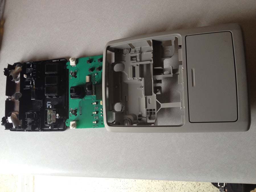
CB2775AHL5
Apr 29, 2013Universal Garage Door Opener w/ FHSS TX
Equipment Class
DSR - Part 15 Remote Control/Security Device Transceiver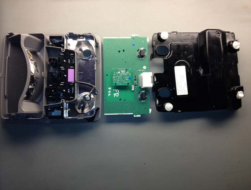
CB2440AHL5
Feb 24, 2013Universal Garage Door TX w/ FHSS TX
Equipment Class
DSS - Part 15 Spread Spectrum Transmitter