CB2BLUECONHands-Free Telephone Module Interface
Johnson Controls Interiors L.L.C.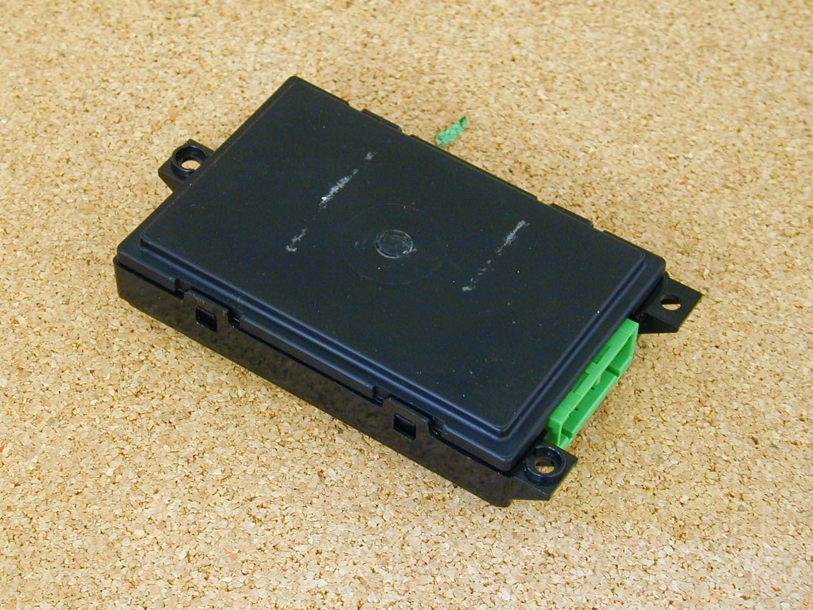
Click to zoom
Application Details
- Equipment Class
- DSS - Part 15 Spread Spectrum Transmitter
- Date of Grant
- Jul 30, 2003
- Application Purpose
- Original Equipment
- Date of Application
- Jul 30, 2003
- Equipment Note
- Hands-Free Telephone Module Interface
- Frequency Range
- 2402.00000000 - 2480.00000000
- Country
- United States
Documents & Files
Document Text
Text extracted from the exhibit documents filed with the FCC. Open a document above to read the original.
Users Manual
Re: Certification for JCI CB2BLUECON Transmitter Model: CB2BLUECON FCC ID: CB2BLUECON IC: 279B-BLUECON USER'S MANUAL INFORMATION (PRELIMINARY) The User's Manual is in preparation. The following material will be contained in the manual: FCC ID: CB2BLUECON IC: 279B-BLUECON This device complies with Part 15 of the FCC Rules and with RSS-210 of Industry Canada. Operation is subject to the following two conditions: (1) This device may not cause harmful interference, and (2) This device must accept any interference received, including interference that may cause undesired operation. WARNING: Changes or modifications not expressively approved by the party responsible for compliance could void the user's authority to operate the equipment. The term “IC:” before the radio certification number only signifies that Industry Canada technical specifications were met. Draft Copy Honda Hands-Free Telephone Module Interface JCI-Suggested User Guide Text User Guide CT-ELE-003-Preliminary (4.0) Johnson Controls, Inc. Automotive Systems Group Interiors Electronics One Prince Center Holland, MI 49423 Note: This document is a Johnson Controls, Inc. confidential document. Disclosure must be controlled by the recipient. Draft Copy Copyright Notice This manual is the property of Johnson Controls Incorporated and is for the exclusive use of its employees or assignees. Its contents are not to be disclosed to outside parties without the permission of Johnson Controls Incorporated. No part of this manual may be reproduced in any form whatsoever, without the permission of Johnson Controls Incorporated. Note: This document is a Johnson Controls Incorporated confidential document. Disclosure must be controlled by the recipient. 2003 Johnson Controls Interiors. All rights reserved. Trademarks Bluetooth is a trademark owned by the Bluetooth SIG, Inc. Other product names and company names found in this manual may be the trademarks of their respective holders. User Manual Release Approval Core Product Lead Engineer: Date: Revisions Version Date Description Who Preliminary December 11, 2002 Preliminary based on SRS 3.0. Pat Lamotte Preliminary April 24, 2003 Modified Figure 2, "Voice Prompts 2". Changed the "press and hold" times from 1.5 to 1.2 seconds. Made many changes to the voice commands. Updated the "Clearing the System of All Stored Information" Caution statement. Updated the "Pairing a Phone to the HFTM System" Caution statement. Made various changes to the instruction steps throughout the guide. Deleted the "Selecting Another Phone" section. Updated the "Transferring" instructions and the "Go Back" and "Cancel" sections. Pat Lamotte Continued... Draft Copy Revisions (Continued...) Version Date Description Who Preliminary June 25, 2003 Added "BLUECONN" to FCC label in back of document. Pat Lamotte Johnson Controls, Inc. Automotive Systems Group Interiors Electronics One Prince Center Holland, MI 49423 ii Draft Copy Table of Contents Learning About the HFTM .......................................................................1 Precautions ........................................................................................... 1 Introduction ........................................................................................... 1 Helpful Hints ......................................................................................... 4 Using the HFTM Buttons ................................................................. 4 Using Shortcuts ............................................................................... 4 Using Icons in this Guide ................................................................. 5 Global Commands ................................................................................ 5 Help ................................................................................................. 5 Go Back........................................................................................... 5 Cancel ............................................................................................. 6 Using the HFTM System ..........................................................................6 Using the Phonebook............................................................................ 6 Storing a Name Tag with Number ................................................... 6 Editing the Number for a Current Phonebook Entry ........................ 7 Deleting a Stored Phonebook Entry ................................................ 7 Listing all Entries in the Phonebook................................................. 8 Navigating the Phonebook .............................................................. 8 Editing List Entries in the Phonebook .............................................. 9 Deleting List Entries in the Phonebook............................................ 9 Setup .................................................................................................. 10 Listing Paired Phones.................................................................... 10 Editing a Phone Name from the Phone List................................... 10 Renaming a Paired Phone ............................................................ 10 Renaming a Paired Phone if You Know Its Name.................... 10 Renaming a Paired Phone if You Don't Know its Name........... 11 Clearing the System of All Stored Information ............................... 11 Setting the Gender of Voice Prompts ............................................ 12 Using the Security System .................................................................. 12 Setting the Passcode for the System............................................. 12 iii Draft Copy Locking the System.......................................................................13 Unlocking the System ....................................................................13 Using the Phone.................................................................................…
Text truncated - open the document above for the full version.
Block Diagram
Microprocessor: (3.6864Mhz) Bluetooth Baseband and Transceiver BCM BlueConnect Hands-Free Module Bluetooth:(15.36Mhz) Transient Protection Power Regulation Power Supply 1.8 V, 3.3 V ACC Audio Bluetooth Antenna 15.36 MHz Crystal Standard UART GPIO[46,47] Audio Out (L/R) Flash 16 MByte (128 Mbits) SDRAM 16 MByte (128 Mbits) Fully Functional UART GPIO[34,39] BT UART GPIO[42-45] AC97 Interface 57600 kb/s AC-97 CODEC: (24.576 MHz) AC-Link Audio Out (L/R) Vehicle Audio I/F 3.3 V, 5 V +B SSP B-CAN:4Mhz 1.1 V, 3.3 V User Interface (Two Buttons) Transceiver/uP RS485 MIC IN Program RAMBT BasebandBT Radio Audio MUX RS485
Cover Letter(s)
Re: Certification for JCI CB2BLUECON Transmitter Model: CB2BLUECON FCC ID: CB2BLUECON IC: 279B-BLUECON REQUEST FOR CONFIDENTIALITY Pursuant to 47 CRF 0.459, JCI requests that a part of the subject application be held confidential. This comprises Exhibits (5) Schematics (10) Parts List (Part of Exhibit only) JCI has spent substantial effort in developing this product and it is one of the first of its kind in industry. Having the subject information easily available to "competition" would negate the advantage they have achieved by developing this product. Not protecting the details of the design will result in financial hardship. If there are any questions regarding this request, please contact me at the above address or call 734-483-4211, fax 734-647-2106 or e-mail [email protected]. Sincerely, Valdis V. Liepa Research Scientist University of Michigan
Cover Letter(s)
American Telecommunications Certification Body Inc. 6731 Whittier Ave, McLean, VA 22101 July 16, 2003 RE: FCC ID: CB2BLUECON_ATCB000595 Attention: Val Liepa I have a few comments on this Application. 1. Please note that the statement (“the radiated emissions are subject to emissions in restricted bands only (15.205)” is incorrect. While 15.247 intentional radiators are not subject to the general 15.209 limits, they are subject to a radiated spurious emissions requirement of at least 20dB below the fundamental frequency requirement as well as the restricted band emissions requirements (above and below 1GHz). Please clarify your statement so that the test report shows understanding of this requirement. 2. Please note that your report states that the open site facility of the University is listed with the FCC, yet your report states that you did full radiated compliance in an anechoic chamber. While preliminary radiated testing to find the worse case setup may be used, the actual site used to perform final emissions testing (at least in the frequency range below 1GHz) must be the site listed. Please show how your device radiated emissions testing was performed on the required FCC listed site. Alternately, please provide evidence that the anechoic chamber is listed with the FCC as an acceptable site. 3. FYI – no action needed. Please note that the conducted testing performed on the device is under the old rules. The new conducted emissions range is from 150 KHz to 30 MHz. By testing to the old rules the device must either be retested prior to the deadline specified in 15.37 (transition rule) or must stop being sold as specified in the transition rule. The grant note for devices tested to the old rule part will be 05 indicating it is subject to the transition limitations. 4. FYI – no action needed. Please note that Bluetooth devices have at least three modes of operation (DH1, DH3 and DH5). The two ‘worse’ case conditions can usually be found in the transmit (data mode) and the inquiry mode. These are the two modes that will always be functioning during normal operation. Please also note that the hopping channel requirements apply to not only the transmit mode but also to the inquiry mode. Even Bluetooth protocol would indicate mandatory compliance; evidence of compliance to the hopping channels should also be done for the inquiry mode. 5. The FCC requires that a separate MPE report be uploaded and provided to them. Please provide a separate MPE document. 6. In the radiated emissions table 5.1 you show peak readings above the average limit. While these peak readings are compliant to the 20dB over the average limit (74dBuV/m) requirement, they fail the actual average limit of 54dBuV/m. Please note that assumptions about Bluetooth device operations such as made in 6.5 of your report cannot be made for the purpose of showing compliance. Actual average measurements MUST be used to show compliance. Please provide average measurements showing compliance to the 54dB limits. 7. Please note that while it appears that the white blank spot on the device is where the label may go, this cannot be assumed. Please specify where on the device the label is to be located. 8. The report indicates a modified device for making conducted antenna measurements. The internal photos show a device with an SMA connector. The schematics state an inverted F antenna connection is used. Please explain the difference in documentation on the rf connector used in this device. Please show how the antenna restrictions of part 15 are met. 9. FYI – no action needed at this time. Please note that the FCC may request that the shield covering the digital circuitry portion of the PCB be removed to show the circuitry underneath. z Page 2 July 16, 2003 Dennis Ward mailto:[email protected] The items indicated above must be submitted before processing can continue on the above referenced application. Failure to provide the requested information may result in application termination. Correspondence should be considered part of the permanent submission and may be viewed from the Internet after a Grant of Equipment Authorization is issued. Please do not respond to this correspondence using the email reply button. In order for your response to be processed expeditiously, you must submit your documents through the AmericanTCB.com website. Also, please note that partial responses increase processing time and should not be submitted. Any questions about the content of this correspondence should be directed to the sender.
Cover Letter(s)
RE: FCC ID: CB2BLUECON_ATCB000595 The following is in response to the comments on the above application. 1. Please note that the statement (“the radiated emissions are subject to emissions in restricted bands only (15.205)” is incorrect. While 15.247 intentional radiators are not subject to the general 15.209 limits, they are subject to a radiated spurious emissions requirement of at least 20dB below the fundamental frequency requirement as well as the restricted band emissions requirements (above and below 1GHz). Please clarify your statement so that the test report shows understanding of this requirement. It is evident from the test report that this requirement was understood. However, we have removed “only” from this statement in the test report per your request. 2. Please note that your report states that the open site facility of the University is listed with the FCC, yet your report states that you did full radiated compliance in an anechoic chamber. While preliminary radiated testing to find the worse case setup may be used, the actual site used to perform final emissions testing (at least in the frequency range below 1GHz) must be the site listed. Please show how your device radiated emissions testing was performed on the required FCC listed site. Alternately, please provide evidence that the anechoic chamber is listed with the FCC as an acceptable site. The DUT is used exclusively in a transportation vehicle, and pursuant to section 15.103 of the FCC rules all digital emissions from the device are exempt. All emissions from this device resulting from the RF section fall well above 1 GHz - this was verified in pre-testing. If emissions resulting from the RF section had been detected below 1 GHz, then testing (below 1 GHz) would be done on the FCC listed OATS pursuant to the FCC guidelines. 3. FYI – no action needed. Please note that the conducted testing performed on the device is under the old rules. The new conducted emissions range is from 150 KHz to 30 MHz. By testing to the old rules the device must either be retested prior to the deadline specified in 15.37 (transition rule) or must stop being sold as specified in the transition rule. The grant note for devices tested to the old rule part will be 05 indicating it is subject to the transition limitations. These tables are in the process of being updated. Note that no conducted testing need be performed on the device in question. 4. FYI – no action needed. Please note that Bluetooth devices have at least three modes of operation (DH1, DH3 and DH5). The two ‘worse’ case conditions can usually be found in the transmit (data mode) and the inquiry mode. These are the two modes that will always be functioning during normal operation. Please also note that the hopping channel requirements apply to not only the transmit mode but also to the inquiry mode. Even Bluetooth protocol would indicate mandatory compliance; evidence of compliance to the hopping channels should also be done for the inquiry mode. 5. The FCC requires that a separate MPE report be uploaded and provided to them. Please provide a separate MPE document. Our apologies, one has been uploaded. 6. In the radiated emissions table 5.1 you show peak readings above the average limit. While these peak readings are compliant to the 20dB over the average limit (74dBuV/m) requirement, they fail the actual average limit of 54dBuV/m. Please note that assumptions about Bluetooth device operations such as made in 6.5 of your report cannot be made for the purpose of showing compliance. Actual average measurements MUST be used to show compliance. Please provide average measurements showing compliance to the 54dB limits. Section 6.5 of the test report has been updated to include a sample measurement, demonstrating the peak to average ratio for the device in question is much greater than 20 dB. Pursuant to 15.35, peak measurements are then used to demonstrate compliance. 7. Please note that while it appears that the white blank spot on the device is where the label may go, this cannot be assumed. Please specify where on the device the label is to be located. An updated ID Label & Location Exhibit has been uploaded. 8. The report indicates a modified device for making conducted antenna measurements. The internal photos show a device with an SMA connector. The schematics state an inverted F antenna connection is used. Please the difference in documentation on the RF connector used in this device. Please show how the antenna restrictions of part 15 are met. The two internal photos showing the SMA connector are simply demonstrating how the modified device was constructed. Other photos in the exhibit show the non-modified device with the inverted F antenna. A new Internal Photos exhibit has been uploaded with the word “Modified” added to the photos in question. 9. FYI – no action needed at this time. Please note that the FCC may request that the shield covering the digital circuitry portion of the PCB be removed to show the circuitry underneath.
Operational Description
BlueConnect Theory of Operation The BlueConnect module is a hands-free interface to Bluetooth enabled devices. By connecting to the vehicle bus and radio, the user is able to interact with a fully vehicle integrated system from the OEM. A voice recognition engine allows the user to control the system throughout a variety of functions. Interaction with the voice recognizer is accomplished via a microphone mounted in a manufacturer-chosen location. Further user interface (switches and voice recognizer) details are specific to the manufacturer’s preference. The primary processor of the system runs the voice recognizer as well as general function manager. The general function manager calls other functions as necessary based upon feedback from the vehicle bus, the user (via voice recognition and/or the button interface), or Bluetooth and the connected Bluetooth device(s). Memory, composed of separate RAM and FLASH, allow for reprogramming and upgrades of the system as new features are developed. The memory is also used for voice recognition libraries and other Bluetooth devices that have been paired to the system. Other user-specific features and configurations are saved here as well. A Bluetooth link to paired devices is used for the audio gateway through the system. By using the Bluetooth protocol, the module is able to connect to several different devices and route the audio out to the vehicle radio. The interface to the vehicle radio is configurable for single-ended audio, differential audio, or stereo versions of either configuration.
RF Exposure Info
Potential Health Hazard EM Radiation Level It has been determined that the DUT output power is less than 10 mW (10 dBm), and given the low gain of the PCB antenna (~1 dBi) , no health hazard exists beyond the physical dimensions of the DUT. The following table summarizes the minimum operating distance for this device as calculated from FCC OET Bulletin 65. Table 6.3 Potential Health Hazard Radiation Level Ant. Ant.Gain (dB) Po (mW) EIRP (mW) R (cm) PCB 1 1.12 1.42 0.34 The following equations were used in calculating the operating distance (R). 10 )( 10)()( dBGain mWPomWEIRP⋅= and )/(4 )( 2 cmmWS mWEIRP R ⋅Π⋅ =, S = 1mW/cm 2
Test Report
1 The University of Michigan Radiation Laboratory 3228 EECS Building Ann Arbor, MI 48109-2122 Tel: (734) 764-0500 Measured Radio Frequency Emissions From Johnson Controls Model: CB2-BLUECONN Report No. 173 July 31, 2003 Copyright © 2003 For: Johnson Controls Interiors L.L.C. One Prince Center Holland, MI 49423 Contact: Jeremy Bos Tel: (616) 394-6076 Fax: (616) 394-6100 PO: Verbal Tests supervised by: Measurements made by: Report approved by: _____________________ Joseph D. Brunett Valdis V. Liepa Edward A. Courtney Research Scientist Summary Tests for compliance with FCC Regulations, Part 15.247, and with Industry Canada (IC) Regulations, RSS-210, Part 6.2.2, were performed on Johnson Controls model CB2- BLUECONN frequency hopping spread spectrum (FHSS) transmitter. The DUT is subject to the Rules and Regulations as a transmitter. In testing competed on 11-Jun-03, the radiated emissions in restricted bands were met by 8.0 dB. The AC line conducted emissions tests do not apply, since the device is powered from a 12 VDC system. The DUT is exempt as a digital device since it is used in a transportation vehicle. All other testing indicates that the Johnson Controls model CB2-BLUECONN meets the limitations set forth by the FCC and IC for a 2.4 GHz FHSS transmitter. 2 1. Introduction Johnson Controls model CB2-BLUECONN was tested for compliance with FCC Regulations, Part 15, Subpart C, adopted under Docket 87-389, April 18, 1989, and with Industry Canada RSS-210, Issue 5, November, 2001. The tests were performed at the University of Michigan Radiation Laboratory Willow Run Test Range following the procedures described in ANSI C63.4-1992 "Methods of Measurement of Radio-Noise Emissions from Low-Voltage Electrical and Electronic Equipment in the Range of 9 kHz to 40 GHz". The Site description and attenuation characteristics of the Open Site facility are on file with FCC Laboratory, Columbia, Maryland (FCC Reg. No: 91050) and with Industry Canada, Ottawa, ON (File Ref. No: IC 2057). 2. Test Procedure and Equipment Used The pertinent test equipment commonly used in our facility for measurements is listed in Table 2.1 below. The middle column identifies the specific equipment used in these tests. Table 2.1 Test Equipment Test Instrument Eqpt. Used Manufacturer/Model Spectrum Analyzer (0.1-1500 MHz) Hewlett-Packard, 182T/8558B Spectrum Analyzer (9kHz-22GHz) X Hewlett-Packard 8593A SN: 3107A01358 Spectrum Analyzer (9kHz-26GHz) X Hewlett-Packard 8593E, SN: 3412A01131 Spectrum Analyzer (9kHz-26GHz) Hewlett-Packard 8563E, SN: 3310A01174 Spectrum Analyzer (9kHz-40GHz) Hewlett-Packard 8564E, SN: 3745A01031 Power Meter X Hewlett-Packard, 432A Power Meter Anritsu, ML4803A/MP Peak Power Meter Pacific Instruments 1018B Harmonic Mixer (26-40 GHz) Hewlett-Packard 11970A, SN: 3003A08327 Harmonic Mixer (40-60 GHz) Hewlett-Packard 11970U, SN: 2332A00500 Harmonic Mixer (75-110 GHz) Hewlett-Packard 11970W, SN: 2521A00179 Harmonic Mixer (140-220 GHz) Pacific Millimeter Prod., GMA, SN: 26 S-Band Std. Gain Horn X S/A, Model SGH-2.6 C-Band Std. Gain Horn X University of Michigan, NRL design XN-Band Std. Gain Horn X University of Michigan, NRL design X-Band Std. Gain Horn X S/A, Model 12-8.2 X-band horn (8.2- 12.4 GHz) X Narda 640 X-band horn (8.2- 12.4 GHz) Scientific Atlanta , 12-8.2, SN: 730 K-band horn (18-26.5 GHz) X FXR, Inc., K638KF Ka-band horn (26.5-40 GHz) X FXR, Inc., U638A U-band horn (40-60 GHz) Custom Microwave, HO19 W-band horn(75-110 GHz) Custom Microwave, HO10 G-band horn (140-220 GHz) Custom Microwave, HO5R Bicone Antenna (30-250 MHz) X University of Michigan, RLBC-1 Bicone Antenna (200-1000 MHz) X University of Michigan, RLBC-2 Dipole Antenna Set (30-1000 MHz) X University of Michigan, RLDP-1,-2,-3 Dipole Antenna Set (30-1000 MHz) EMCO 2131C, SN: 992 Active Rod Antenna (30 Hz-50 MHz) EMCO 3301B, SN: 3223 Active Loop Antenna (30 Hz-50 MHz) EMCO 6502, SN:2855 Ridge-horn Antenna (300-5000 MHz) X University of Michigan Amplifier (5-1000 MHz) X Avantak, A11-1, A25-1S Amplifier (5-4500 MHz) X Avantak Amplifier (4.5-13 GHz) X Avantek, AFT-12665 Amplifier (6-16 GHz) X Trek Amplifier (16-26 GHz) X Avantek LISN Box University of Michigan Signal Generator Hewlett-Packard 8657B 3 3. Configuration and Identification of Device Under Test The DUT is a frequency hopping spread spectrum (FHSS) transmitter operating in 2400 - 2483.5 MHz band. The DUT is 3 x 4 x 1.5 inches, and connects to a peripheral laptop computer via a serial interface card for testing purposes. The system has been designed to operate with 79 channels spaced 1 MHz apart between 2402 MHz and 2480 MHz. The DUT has only one antenna built into the PCB. The DUT was designed and manufactured by Johnson Controls Interiors L.L.C., One Prince Center, Holland, MI 49423. It is identified as: Johnson Controls Bluetooth Module Model: CB2-BLUECONN SN: Proto1 FCC ID: CB2-BLUECONN IC: 279B-BLUECONN In addition to a standard unit, a modified unit was provided by the manufacturer which had the internal antenna disabled and a SMA connector attached for conducted antenna measurement purposes. Peripheral Equipment: Laptop Computer Compaq Presario SN: V745BQD22994 Model: Series 2940 FCC ID: CNTTAI-24639-TT-E Serial Interface Card SN: Proto1 3.1 EMI Relevant Modifications No modifications were made to the DUT by this laboratory during testing. 4 4. Emission Limits 4.1 Radiated Emission Limits Since the DUT is a spread spectrum device (15.247, 2.4 GHz), the radiated emissions are subject to emissions in restricted bands (15.205). The applicable frequencies, through ten harmonics, are given below in Table 4.1. Emission limits from digital circuitry are specified in Table 4.2. Table 4.1 Radiated Emission Limits (FCC:15.205; IC:RSS-210, 6.3) - Transmitter Fundamental Spurious* Frequency Ave. E lim (3m) Ave. E lim (3m) (MHz) (μV/m) dB (μV/m) (μV/m) dB (μV/m) 2400-2483.5 --- --- 2310-2390 Restricted 500 54.0 2483.5-2500 Bands 4500-5250 Bands 7250-7750 500 54.0 14470-14500 17700…
Text truncated - open the document above for the full version.
Contact Information
Applicant
Rick Markiewicz(Electronics Engineering Manager)
Technical Contact
University of Michigan/EECSValdis V Liepa
[email protected]734-483-4211
1301 Beal Ave. · Ann Arbor, Michigan · United States
Test Firm
University of MichiganValdis Liepa
Technical Specifications
| # | Rule Parts | Frequency Range | Power Output |
|---|---|---|---|
| 1 | 15C | 2.40 GHz - 2.48 GHz | 1.20 mW |
Other Applications from Johnson Controls Interiors L.L.C.

CB2-BLUE15M-TCU
Mar 20, 2014Automotive Telematics Module with Handsfree Bluetooth
Equipment Class
DSS - Part 15 Spread Spectrum Transmitter
CB2-BLUE15M
Jan 19, 2014Bluetooth Telematics Device
Equipment Class
DSS - Part 15 Spread Spectrum Transmitter
CB262932
Jul 15, 2013Automotive Electronics Infotainment Head Unit with Bluetooth and WLAN
Equipment Class
DTS - Digital Transmission System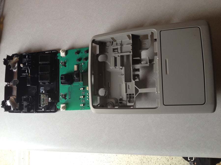
CB2775AHL5
Apr 29, 2013Universal Garage Door Opener w/ FHSS TX
Equipment Class
DSR - Part 15 Remote Control/Security Device Transceiver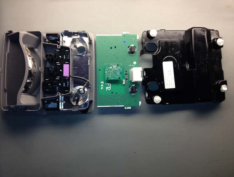
CB2440AHL5
Feb 24, 2013Universal Garage Door TX w/ FHSS TX
Equipment Class
DSS - Part 15 Spread Spectrum Transmitter