CB2BMWHL3Universal Garage Door Opener
Johnson Controls Interiors L.L.C.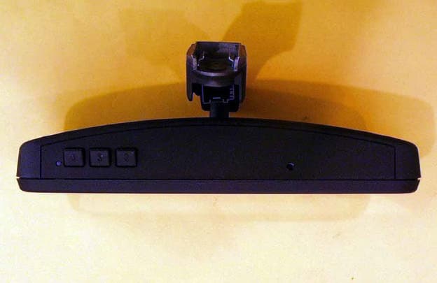
Click to zoom
Application Details
- Equipment Class
- DSC - Part 15 Security/Remote Control Transmitter
- Date of Grant
- Jul 08, 2001
- Application Purpose
- Original Equipment
- Date of Application
- Jul 08, 2001
- Equipment Note
- Universal Garage Door Opener
- Frequency Range
- 411.00000000 - 420.00000000
- Country
- United States
Documents & Files
Document Text
Text extracted from the exhibit documents filed with the FCC. Open a document above to read the original.
Users Manual
The Owners Manual for the Homelink® series Universal Garage Door Opener is reproduced here. HomeLink ® Universal Transceiver Suggested Owner’s Manual Text October, 2000 HomeLink ® Universal Transceiver The HomeLink ® Universal Transceiver in your vehicle provides a convenient way to replace up to three hand- held transmitters with a single built-in component. This innovative feature will learn the radio frequency codes of most current transmitters used to activate devices such as garage doors, entry door locks, estate gates, security systems, and home or office lighting. For additional information on HomeLink and/or HomeLink compatible products, call 1-800-355-3515 or refer to the HomeLink web site at www.home link.jci.com . Precautions When programming the HomeLink Universal Transceiver to a garage door opener or entry gate, make sure that people and objects are out of the way to prevent potential harm or damage. Do not use the HomeLink Universal Transceiver with any garage door opener that lacks the safety stop and reverse feature as required by federal safety standards. (This includes any garage door opener model manufactured before April 1, 1982.) A garage door opener which cannot detect an object, signaling the door to stop and reverse, does not meet current federal safety standards. Using a garage door opener without these features increases risk of serious injury or death. For more information, call 1-800-355-3515 or on the internet at www.homelink.jci.com. Retain the original transmitter for future programming procedures (i.e., new vehicle purchase). It is also suggested that upon the sale of the vehicle, the programmed HomeLink Universal Transceiver buttons be erased for security purposes (follow step 1 in the “Programming” portion of this text). Programming Note : For best results, replace the battery in the hand-held transmitter with a new battery before programming. If your garage door opener receiver (located in the garage) is equipped with an antenna, make sure the antenna is completely uncoiled and hangs straight down. 1. Press and hold the two outside buttons - releasing only when the indicator light begins to flash after 20 seconds . (This procedure erases the factory set default codes and does not have to be followed to program additional hand-held transmitters.) 2. Hold the end of the hand-held transmitter of the device you wish to train approximately one to three inches away from the HomeLink surface - keeping the indicator light in view. (For placement questions, please contact HomeLink at 1-800-355-3515 or on the internet at www.home link.jci.com. ) 3. Using both hands, simultaneously push the hand-held transmitter button and the desired HomeLink button. Do not re le ase the buttons until ste p 4 has be e n comple te d. Note: Some entry gates and garage door openers may require you to replace this programming step (#3) with the procedures noted in the “Canadian Programming / Gate Programming” section. 4. The HomeLink indicator light will flash, first slowly and then rapidly. When the indicator light flashes rapidly, release both buttons. (The rapid flashing light indicates successful programming of the new frequency signal.) If, after 20 seconds, the indicator light does not flash rapidly, release both the HomeLink and the hand-held transmitter buttons and repeat steps tw o through four. However, position the hand-held transmitter at a different length and/or angle until the indicator light begins to flash rapidly. Release both buttons after the indicator light flashes rapidly. Refer to “Rolling Code Programming” and/or “Canadian Programming/Gate Programming” for additional procedures if necessary. To activate the garage door or other programmed device upon successfully completing the steps above, press and hold the HomeLink button - releasing when the device begins to activate. To program the remaining tw o buttons, follow steps 2 through 4. If you do not successfully program the HomeLink Universal Transceiver to learn the signal of the hand-held transmitter, refer to “Rolling Code Programming” within this text or call toll-free for customer assistance at 1-800- 355-3515 or on the internet at www.home link.jci.com. Canadian Programming / Gate Programming Canadian frequency law s, and the technology of some entry gates, require you to “cycle” (press and re-press the hand- held transmitter button every tw o seconds) during programming. Continue to press and hold the desired HomeLink button (note steps 3 through 5 in the “Programming” portion of this text) w hile you “cycle” your hand-held transmitter until the frequency signal has been learned. The indicator light w ill flash slowly and then rapidly upon successful training. Note: When programming a garage door opener or gate, it is advised to unplug the device during the “cycling” process to prevent possible motor burn-up Operating the HomeLink ® Universal Transceiver To operate, simply press the programmed HomeLink button. Activation will now occur for the trained product (garage door, security system, entry door lock, estate gate, or home or office lighting). For convenience, the hand-held transmitter of the device may also be used at any time. Rolling Code Programming Rolling code garage door openers (or other rolling code devices) which are “code protected” and manufactured after 1996, may be determined by the following: A.Reference the garage door opener owner’s manual for verification. B.The hand-held transmitter appears to program the HomeLink Universal Transceiver but HomeLink does not activate the garage door. C.Press and hold the trained HomeLink button. The garage door opener has the rolling code feature if the HomeLink indicator light flashes rapidly and then turns solid after 2 seconds. To train a garage door opener with the rolling code feature, follow these instructions after completing the “Programming” portion of this text (the aid of a second person may make the following training procedures quicke…
Text truncated - open the document above for the full version.
Cover Letter(s)
FCC ID: CB2BMWHL3 Request for Confidentiality In accordance with 47 C.F.R. Section 0.459, we, Johnson Control Interiors, L.L.C., hereby request confidentiality for the block diagram, schematic and product description presented for certification. In support of the Request for Confidentiality, the following is stated: Enclosed within this application is technical information which we deem to be trade secrets and proprietary. If made public, the information might be used to our disadvantage. To assist in assuring that we receive the full value of our product and protect its competitive posture, we respectfully request this grant of confidentiality. Johnson Control Interiors, L.L.C.
ID Label/Location Info
Test report #0100410F FCC 15.231 for CB2GTXHL3 FCC ID: CB2GTXHL3 Tested April 4, 2001 AHD EMC Lab, 92723 M152, Dowagiac, MI 49047, (616) 424-7014EXA_Label Exhibit A: Page 1 of 2 EXHIBIT A: EQUIPMENT LABEL [2.925, 2.926, 2.1033(B2,7), 15.19(A3)] LABEL EXAMPLE For the label print, page 2 of this exhibit, Refer to picture file “EXA_Label.pdf” The FCC Identifier assigned to the EUT is FCC ID: CB2GTXHL3. This number will be imprinted on the 1.0”x1.5” high temperature polyester matte white label. Because of the small size of the device and because the installation is inside a portion of the automobile, the following statements will appear in the user’s manual. Refer to Exhibit D for the entire text of the user’s manual. “This device complies with FCC rules Part 15. Operation is subject to the following two conditions: (1) This device may not cause harmful interference, and (2) This device must accept any interference that may be received including interference that may cause undesired operation. WARNING: The transmitter has been tested and complies with FCC and DOC/MDC rules. Changes or modifications not expressly approved by the party responsible for compliance could void the user’s authority to operate the device.” LABEL LOCATION The label will be placed on the foil side of the CB2GTXHL3 PCB using an acrylic adhesive that will permanently affix the label.
Parts List/Tune Up Info
Test report #0100410F FCC 15.231 for CB2GTXHL3 FCC ID: CB2GTXHL3 Tested April 4, 2001 AHD EMC Lab, 92723 M152, Dowagiac, MI 49047, (616) 424-7014EXmisc_PartsTune Misc. EXHIBIT: Page 1 of 3 MISC. EXHIBIT: PARTS LIST / TUNING INFORMATION [2.1033(B5)] The Parts List and Component Placement Diagram portion of this Misc. EXHIBIT is located in the “pdf” file entitled “EXmisc_Parts.pdf”. Tuning: (Programming) The user programs the CB2GTXHL3 as outlined in the Users Manual, Exhibit D. A summary is provided here. 1. Pressing the two outside buttons until the indicator LED begins to flash resets the memory. 2. Holding the hand-held transmitter to be copied near the CB2GTXHL3 and simultaneously activating the hand-held transmitter and one of the user buttons until the indicator LED flashed rapidly trains the unit to duplicate the hand-held transmitter. The information is stored in the non-volatile memory of the CB2GTXHL3. During usage, when the “trained” button is pressed, the CB2GTXHL3 recalls the stored information. 1. The Voltage Controlled Oscillator (VCO) is set on the desired RF carrier frequency. 2. The antenna is coarse tuned by sweeping twice around the expected tuning point. 3. The antenna is fine tuned with 9 pulses of approximately 210 uS with 11 mS off. 4. The VCO is then modulated with the appropriate garage door opener bit code from the non- volatile memory.
RF Exposure Info
Test report #0100410F FCC 15.231 for CB2GTXHL3 FCC ID: CB2GTXHL3 Tested April 4, 2001 AHD EMC Lab, 92723 M152, Dowagiac, MI 49047, (616) 424-7014 EXmisc_RFexpose Misc. EXHIBIT: Page 3 of 3 MISC. EXHIBIT: RF EXPOSURE INFORMATION [2.1093(C)] The manufacturer and applicant: JOHNSON CONTROLS INTERIORS, LLC. One Prince Center Holland, Michigan 49423 Product: Homelink® Universal Garage Door Opener Model: CB2GTXHL3 Applicable Rules: 47CFR Part 15.231 Pursuant to 47CFR Part 1.1307(b), 47CFR Part 2.1091(c), and 47CFR Part 2.1093(c) this transmitting device, compliant to 47CFR Part 15.231, is categorically excluded from evaluation regarding the Maximum Permissible Exposure of RF energy.
Test Report
A H D EMC Laboratory 92723 M-152, Dowagiac, MI 49047 USA Phone: (616) 424-7014 www.ahde.com AHD EMC Lab, 92723 M152, Dowagiac, MI 49047, (616) 424-7014EXE_TestRprt EXHIBIT E: Page 1 of 33 EXHIBIT E: REPORT OF MEASUREMENTS [2.1033(B6)] Test Report for FCC ID: CB2GTXHL3 FCC Part 2.1031, Part 15 Subpart C(15.231) Report #0100410F Issued 4/24/01 TRANSMITTER MODEL CB2GTXHL3 OF HOMELINK® III SERIES Prepared for: Mr. David Blaker Johnson Controls Interiors, LLC One Prince Center Holland, MI 49423 Test Date(s): April 3,4, 2001 data recorded by witnessed by Ted Chaffee, NCE Craig Harder Test Engineer, AHD This report prepared by: Ted Chaffee, NCE Technical Manager/Test Engineer, AHD Test report #0100410F FCC 15.231 for CB2GTXHL3 FCC ID: CB2GTXHL3 Tested April 4, 2001 AHD EMC Lab, 92723 M152, Dowagiac, MI 49047, (616) 424-7014EXE_TestRprt EXHIBIT E: Page 2 of 33 TABLE OF CONTENTS EXHIBIT E: Report of Measurements [2.1033(b6)].................................................................................1 TABLE OF CONTENTS...................................................................................................................2 Statements Concerning this Report..................................................................................................3 Manufacturer/Applicant [2.1033(b1)]...............................................................................................4 Measurement/Test Site Facility & Equipment...................................................................................4 Test Site [2.948, 2.1033(b6)].................................................................................................4 Measurement Equipment Used [2.947(d), 15.31(b)].................................................................4 Tested Configuration /Setup: [2.1033(b8)]........................................................................................5 Support Equipment & Cabling..................................................................................................5 Setup Diagram.........................................................................................................................5 Summary of Results:.......................................................................................................................6 Changes made to achieve compliance.....................................................................................7 Standards Applied to Test: [2.1033(b6)]...........................................................................................7 Test Methodology: [2.1033(b6)]........................................................................................................7 FORMULAS AND SAMPLE CALCULATIONS:.........................................................................9 Test Data [2.1033(b6)]...................................................................................................................11 Modulation Characteristics.....................................................................................................11 Relative Emission Level vs. Supply Voltage [15.31(e)]...........................................................13 Occupied Bandwidth [15.231(c)].............................................................................................14 Restricted Bands: [15.205]......................................................................................................15 Radiated Field Strength Measurements: [15.231(b), 15.205].................................................16 Radiated Field Strength Measurements..................................................................................18 APPENDIX: Tune Pulses - Data Details....................................................................................28 Test report #0100410F FCC 15.231 for CB2GTXHL3 FCC ID: CB2GTXHL3 Tested April 4, 2001 AHD EMC Lab, 92723 M152, Dowagiac, MI 49047, (616) 424-7014EXE_TestRprt EXHIBIT E: Page 3 of 33 Statements Concerning this Report Test Traceability: The calibration of all measuring and test equipment and the measured data using this equipment are traceable to the National Institute for Standards and Technology (NIST). Limitations on results: The test results contained in this report relate only to the Item(s) tested. Any electrical or mechanical modification made to the test item subsequent to the test date shall invalidate the data presented in this report. Any electrical or mechanical modification made to the test item subsequent to this test date shall require an evaluation to verify continued compliance. Limitations on copying: This report shall not be reproduced, except in full, without the written approval of AHD. Limitations of the report: This report shall not be used to claim product endorsement by NVLAP, FCC, or any agency of the US Government. Statement of Test Results Uncertainty: Following the guidelines of NAMAS publication NIS81 and NIST Technical Note 1297, the Measurement Uncertainty at a 95% confidence level is determined to be: ±3.6 dB Test report #0100410F FCC 15.231 for CB2GTXHL3 FCC ID: CB2GTXHL3 Tested April 4, 2001 AHD EMC Lab, 92723 M152, Dowagiac, MI 49047, (616) 424-7014EXE_TestRprt EXHIBIT E: Page 4 of 33 Manufacturer/Applicant [2.1033(b1)] The manufacturer and applicant: JOHNSON CONTROLS INTERIORS, LLC. One Prince Center Holland, Michigan 49423 Measurement/Test Site Facility & Equipment Test Site [2.948, 2.1033(b6)] The AHD test facility is centered on 9 acres of rural property near Sister Lakes, Michigan. The mailing address is 92723 M-152, Dowagiac, Michigan 49047. This test facility is NVLAP accredited (LabCode 200129-0). It has been fully described in a report filed with the FCC and Industry Canada. The original report filed with the FCC is, dated November 5, 1996, was accepted by the FCC in a letter dated January 15, 1997 and reconfirmed July 14, 2000, (31040/SIT 1300F2). The original report filed with Industry Canada, dated August 11, 1…
Text truncated - open the document above for the full version.
Contact Information
Applicant
Rick Markiewicz(Electronics Engineering Manager)
Non-Technical Contact
AHDTed Chaffee
[email protected]1 616 424-7014
Test Firm
AHD EMC LaboratoryGordon Helm
Technical Specifications
| # | Rule Parts | Frequency Range | Power Output |
|---|---|---|---|
| 4 | 15.231 | 411 MHz - 420 MHz | - |
Other Applications from Johnson Controls Interiors L.L.C.

CB2-BLUE15M-TCU
Mar 20, 2014Automotive Telematics Module with Handsfree Bluetooth
Equipment Class
DSS - Part 15 Spread Spectrum Transmitter
CB2-BLUE15M
Jan 19, 2014Bluetooth Telematics Device
Equipment Class
DSS - Part 15 Spread Spectrum Transmitter
CB262932
Jul 15, 2013Automotive Electronics Infotainment Head Unit with Bluetooth and WLAN
Equipment Class
DTS - Digital Transmission System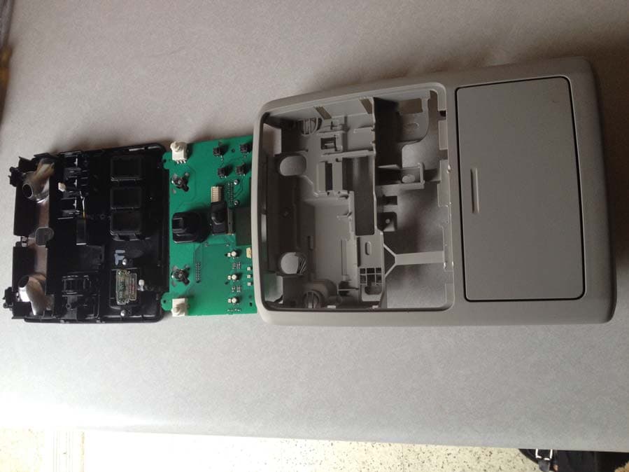
CB2775AHL5
Apr 29, 2013Universal Garage Door Opener w/ FHSS TX
Equipment Class
DSR - Part 15 Remote Control/Security Device Transceiver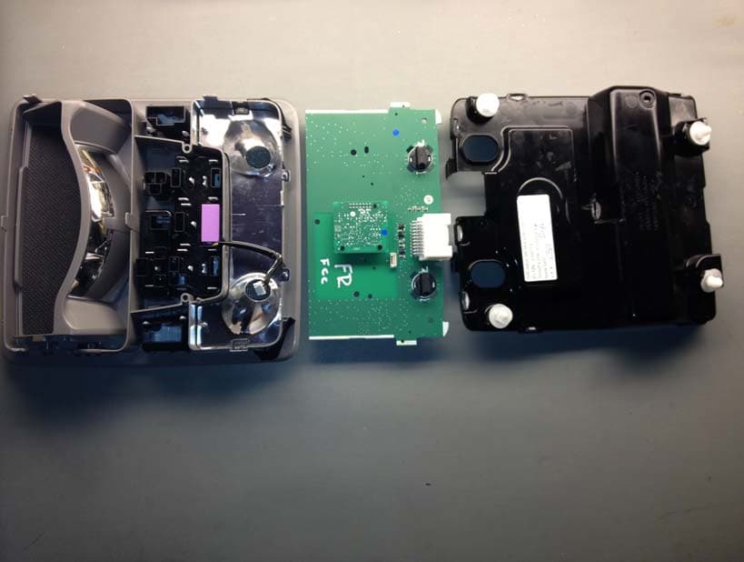
CB2440AHL5
Feb 24, 2013Universal Garage Door TX w/ FHSS TX
Equipment Class
DSS - Part 15 Spread Spectrum Transmitter