CB2CSPSIHL3PSI Receiver for Electronic Vehicle Info System
Johnson Controls Interiors L.L.C.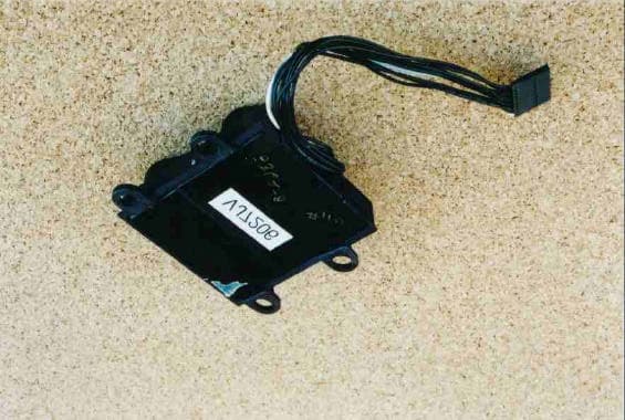
Click to zoom
Application Details
- Equipment Class
- CYY - Communications Receiver used w/Pt 15 Transmitter
- Date of Grant
- Jan 22, 2002
- Application Purpose
- Original Equipment
- Date of Application
- Jan 22, 2002
- Equipment Note
- PSI Receiver for Electronic Vehicle Info System
- Frequency Range
- 433.92000000 - 433.92000000
- Country
- United States
Documents & Files
Document Text
Text extracted from the exhibit documents filed with the FCC. Open a document above to read the original.
Users Manual
Re: Certification for JCI CSPSIHL3 Transmitter / Receiver Model: CSPSIHL3 FCC ID: CB2CSPSIHL3 CANADA: to be provided by IC USER'S MANUAL INFORMATION (PRELIMINARY) The User's Manual is in preparation. The following material will be contained in the manual: FCC ID: CB2CSPSIHL3 CANADA: to be provided by IC This device complies with Part 15 of the FCC Rules and with RSS-210 of Industry Canada. Operation is subject to the following two conditions: (1) This device may not cause harmful interference, and (2) This device must accept any interference received, including interference that may cause undesired operation. WARNING: Changes or modifications not expressively approved by the party responsible for compliance could void the user's authority to operate the equipment. The Owners Manual for the Homelink® series Universal Garage Door Opener is reproduced here. HomeLink ® Universal Transceiver Suggested Owner’s Manual Text October, 2000 HomeLink ® Universal Transceiver The HomeLink ® Universal Transceiver in your vehicle provides a convenient way to replace up to three hand- held transmitters with a single built-in component. This innovative feature will learn the radio frequency codes of most current transmitters used to activate devices such as garage doors, entry door locks, estate gates, security systems, and home or office lighting. For additional information on HomeLink and/or HomeLink compatible products, call 1-800-355-3515 or refer to the HomeLink web site at www.homelink.jci.com. Precautions When programming the HomeLink Universal Transceiver to a garage door opener or entry gate, make sure that people and objects are out of the way to prevent potential harm or damage. Do not use the HomeLink Universal Transceiver with any garage door opener that lacks the safety stop and reverse feature as required by federal safety standards. (This includes any garage door opener model manufactured before April 1, 1982.) A garage door opener which cannot detect an object, signaling the door to stop and reverse, does not meet current federal safety standards. Using a garage door opener without these features increases risk of serious injury or death. For more information, call 1-800-355-3515 or on the internet at www.homelink.jci.com. Retain the original transmitter for future programming procedures (i.e., new vehicle purchase). It is also suggested that upon the sale of the vehicle, the programmed HomeLink Universal Transceiver buttons be erased for security purposes (follow step 1 in the “Programming” portion of this text). Programming Note: For best results, replace the battery in the hand-held transmitter with a new battery before programming. If your garage door opener receiver (located in the garage) is equipped with an antenna, make sure the antenna is completely uncoiled and hangs straight down. 1. Press and hold the two outside buttons - releasing only when the indicator light begins to flash after 20 seconds. (This procedure erases the factory set default codes and does not have to be followed to program additional hand-held transmitters.) 2. Hold the end of the hand-held transmitter of the device you wish to train approximately one to three inches away from the HomeLink surface - keeping the indicator light in view. (For placement questions, please contact HomeLink at 1-800-355-3515 or on the internet at www.homelink.jci.com.) 3. Using both hands, simultaneously push the hand-held transmitter button and the desired HomeLink button. Do not release the buttons until step 4 has been completed. Note: Some entry gates and garage door openers may require you to replace this programming step (#3) with the procedures noted in the “Canadian Programming / Gate Programming” section. 4. The HomeLink indicator light will flash, first slowly and then rapidly. When the indicator light flashes rapidly, release both buttons. (The rapid flashing light indicates successful programming of the new frequency signal.) If, after 20 seconds, the indicator light does not flash rapidly, release both the HomeLink and the hand-held transmitter buttons and repeat steps two through four. However, position the hand-held transmitter at a different length and/or angle until the indicator light begins to flash rapidly. Release both buttons after the indicator light flashes rapidly. Refer to “Rolling Code Programming” and/or “Canadian Programming/Gate Programming” for additional procedures if necessary. To activate the garage door or other programmed device upon successfully completing the steps above, press and hold the HomeLink button - releasing when the device begins to activate. To program the remaining two buttons, follow steps 2 through 4. If you do not successfully program the HomeLink Universal Transceiver to learn the signal of the hand-held transmitter, refer to “Rolling Code Programming” within this text or call toll-free for customer assistance at 1-800- 355-3515 or on the internet at www.homelink.jci.com. Canadian Programming / Gate Programming Canadian frequency laws, and the technology of some entry gates, require you to “cycle” (press and re-press the hand-held transmitter button every two seconds) during programming. Continue to press and hold the desired HomeLink button (note steps 3 through 5 in the “Programming” portion of this text) while you “cycle” your hand-held transmitter until the frequency signal has been learned. The indicator light will flash slowly and then rapidly upon successful training. Note: When programming a garage door opener or gate, it is advised to unplug the device during the “cycling” process to prevent possible motor burn-up Operating the HomeLink ® Universal Transceiver To operate, simply press the programmed HomeLink button. Activation will now occur for the trained product (garage door, security system, entry door lock, estate gate, or home or office lighting). For convenience, the hand- held transmitter of the device may also be used at any time. Rolling Code Programming Roll…
Text truncated - open the document above for the full version.
Block Diagram
ASIC HLIII EEPROM HLIII/PSI CORE INFO MICRO CONTROLLER RF FUNCTIONS HLIII/PSI MICRO CONTROLLER SYSTEM FUNCTIONS J1850 HL USER INTERFACE DIAGNOSTICS J1850 TRANCIEVER POWER SUPPLY & TRANSIENT PROTECTION SWITCH INTERFACE Dot Matrix Display C O N N E C T O R BATT IGNITION GROUND CLASSII/J1850 Homelink Antenna INTEGRATED HOMELINK/PSI SYSTEM J1850 INTERFACE PACKAGE PROTECTED COMPASS ASIC S 1 S 2 Antenna Tunning 433.92MHz PSI Antenna Low Noise Amplifier DUTY CYCLE WAKEUP CIRCUIT LOW CURRENT POWER SUPPLY Switch Battery to Ignition when Ignition is off and Homelink is activated. SAW BAND PASS FILTER High Accuracey and Low Current VCO
Cover Letter(s)
Re: Certification for JCI CSPSIHL3 Transmitter / Receiver Model: CSPSIHL3 FCC ID: CB2CSPSIHL3 CANADA: to be provided by IC POWER OF ATTORNEY A letter granting Valdis V. Liepa the Power of Attorney is on file and can be provided when so requested. Comments regarding operation and testing of the DUT The DUT has been tested for compliance with FCC 15.231(b) and RSS 210; 6.1 and 6.3. 1) Per 15.231(b), the DUT initiates transmission when button is depressed and ceases to transmit within 5 seconds of when the button is released. 2) Under part 15.231(b)(2) of the FCC rules requires the use of an average detector or Quasi-Peak Detector. Because this is a pulse device, and we the guidelines of section 15.35(c), per 15.231(b), wherein the average measurement is obtained by mathematically averaging the peak value. 3) Per 15.231, the DUT transmits only identification and control signals; there is no provision for input of data. Re: Certification for JCI CSPSIHL3 Transmitter / Receiver Model: CSPSIHL3 FCC ID: CB2CSPSIHL3 CANADA: to be provided by IC REQUEST FOR CONFIDENTIALITY Pursuant to 47 CRF 0.459, JCI requests that a part of the subject application be held confidential. This comprises Exhibits (5) Schematics (10) Parts List (Part of Exhibit only) JCI has spent substantial effort in developing this product and it is one of the first of its kind in industry. Having the subject information easily available to "competition" would negate the advantage they have achieved by developing this product. Not protecting the details of the design will definitely result in a financial hardship. If there are any questions regarding this request, please contact me at the above address or call 734-483-4211, fax 734-647-2106 or e-mail [email protected]. Sincerely, Valdis V. Liepa Research Scientist University of Michigan January 9, 2002 Re: Certification for JCI CSPSIHL3 Transmitter / Receiver Model: CSPSIHL3 FCC ID: CB2CSPSIHL3 CANADA: to be provided by IC STATEMENT OF MODIFICATIONS There were no modifications made to the DUT by this test laboratory. (Also see Section 3.1 of the attached Test Report). _____________________ Valdis V. Liepa Research Scientist Re: Certification for JCI CSPSIHL3 Transmitter / Receiver Model: CSPSIHL3 FCC ID: CB2CSPSIHL3 CANADA: to be provided by IC GENERAL PRODUCT INFORMATION The device, for which certification is pursued, has been designed by: Johnson Controls Interiors L.L.C. One Prince Center Holland, MI 49423 Craig Harder Tel: 616-394-6101 Fax: 616-394-3877 It will be manufactured by: Johnson Controls Interiors L.L.C. One Prince Center Holland, MI 49423 Craig Harder Tel: 616-394-6101 Fax: 616-394-3877 It will be marketed and serviced by: Chrysler Dealers of North America
External Photos
CSPSIHL3 with Harness CSPSIHL3 Top CSPSIHL3 Bottom CSPSIHL3 Keypad Top CSPSIHL3 Keypad Bottom
Internal Photos
CSPSIHL3 Open - Top CSPSIHL3 Open - Bottom CSPSIHL3 PCB - Top CSPSIHL3 PCB - Bottom CSPSIHL3 Keypad Open - Top CSPSIHL3 Keypad Open - Bottom CSPSIHL3 Keypad PCB - Top CSPSIHL3 Keypad PCB - Bottom
Operational Description
CS Compass Mini-Trip Computer Module Description of Operation The CS module consists of three basic sections: the Compass Mini-Trip Computer (CMTC) section, the Homelink section, and the PSI section. The CMTC section provides data to the vehicle via the bus, the vehicle then displays the information on the instrument panel. There are three switches on board, which allow the user to select Homelink operation. The CMTC microprocessor powers up the Homelink section, and communicates to the Homelink microprocessor which channel has been selected. The CMTC sends messages out on the J-1850 bus and then a display in the IP provides the information to the driver. The Homelink transmitter is a radio frequency transceiver device whose primary function is to determine both frequency and bit code format of typical garage door remote control devices and identically re-transmit them to the original garage door opener receiver. The on-board microcontroller maintains the operational frequency band as 288Mhz to 418Mhz excluding forbidden bands of 240MHz to 285MHz, 322MHz to 335.4MHz and 399.9MHz to 410 MHz. The “training” operation is performed by scanning the legal frequencies with a single conversion superheterodyne receiver, looking for valid garage door opener bit code formats. In addition to being frequency and data format adaptive the Homelink transmitter is also RF amplitude adaptive. During the training sequence, the duty factor of the incoming bit code format is evaluated by the microcontroller determining the greatest amount of on-time in a 100 mS window. The duty factor is then used to mathematically adjust the output power in a range of 80% (1.9dB) to an upper limit of 30% (10.5dB) duty cycle. A 9 bit attenuator is adjusted by a closed loop power control algorithm in the microcontroller. After the training sequence the frequency bit code format and attenuator setting is stored in Non Volatile Memory (NVM) and retrieved on subsequent power ups. The VCO is set on the desired RF carrier frequency stored in NVM. The antenna is fine-tuned by sweeping twice around the expected tuning point. The voltage-controlled oscillator (VCO) is then modulated with the appropriate bit code information from the NVM. The basic function of the PSI system is to communicate the tire pressure information to the operator of the vehicle via the bus and the instrument panel. The PSI system consists of two different sections. The first is a superheterodyne radio frequency receiver circuit built into the CMTC. This receiver interfaces with the CMTC to provide general tire pressure data as well as tire pressure-related messages to the driver. These messages include low tire pressure, high tire pressure, training messages, and general messages to service system when the tire pressure sensor transmitters are faulted or have a low battery. The second section is the tire air pressure transmitters that use a 433.92 MHz AM modulation radio frequency transmitter to communicate with the receiver in the EVIC. Each tire has one of these tire pressure sensor transmitters installed in the rims. The transmitters then communicate back to the receiver the pressure information and a unique id code from each tire. In order to train the PSI system to recognize which pressure transducer relates to which tire, the operator must first place the system in training mode via the IP and the Bus. The display in the IP will then prompt the operator which tire to go to first. The operator can then take either a magnet or a 125 kHz transponder within close proximity of the pressure sensor of the tire indicated on the display. These tire pressure sensor transmitters will then send the appropriate message to the CMTC receiver identifying which tire is being trained. This process then needs to be repeated for each of the tires as prompted by the IP display.
Contact Information
Applicant
Rick Markiewicz(Electronics Engineering Manager)
Technical Contact
University of Michigan/EECSValdis V Liepa
[email protected]734-483-4211
1301 Beal Ave. · Ann Arbor, Michigan · United States
Non-Technical Contact
University of Michigan/EECSValdis V Liepa
[email protected]734-483-4211
Test Firm
University of MichiganValdis Liepa
Technical Specifications
| # | Rule Parts | Frequency Range | Power Output |
|---|---|---|---|
| 1 | 15B | 433.92 MHz - 433.92 MHz | - |
Other Applications from Johnson Controls Interiors L.L.C.

CB2-BLUE15M-TCU
Mar 20, 2014Automotive Telematics Module with Handsfree Bluetooth
Equipment Class
DSS - Part 15 Spread Spectrum Transmitter
CB2-BLUE15M
Jan 19, 2014Bluetooth Telematics Device
Equipment Class
DSS - Part 15 Spread Spectrum Transmitter
CB262932
Jul 15, 2013Automotive Electronics Infotainment Head Unit with Bluetooth and WLAN
Equipment Class
DTS - Digital Transmission System
CB2775AHL5
Apr 29, 2013Universal Garage Door Opener w/ FHSS TX
Equipment Class
DSR - Part 15 Remote Control/Security Device Transceiver
CB2440AHL5
Feb 24, 2013Universal Garage Door TX w/ FHSS TX
Equipment Class
DSS - Part 15 Spread Spectrum Transmitter