CB2GTXHL3Universal Garage Door Opener
Johnson Controls Interiors L.L.C.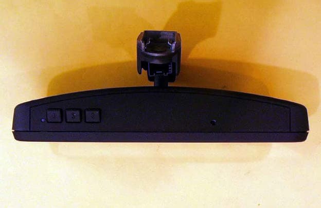
Click to zoom
Application Details
- Equipment Class
- DSC - Part 15 Security/Remote Control Transmitter
- Date of Grant
- May 22, 2001
- Application Purpose
- Original Equipment
- Date of Application
- May 13, 2001
- Equipment Note
- Universal Garage Door Opener
- Frequency Range
- 411.00000000 - 420.00000000
- Country
- United States
Documents & Files
Document Text
Text extracted from the exhibit documents filed with the FCC. Open a document above to read the original.
Cover Letter(s)
AHD EMC Lab, 92723 M152, Dowagiac, MI 49047, (616) 424-7014 TCB_CvrLttr1 Exhibit A: Page 1 of 2 NVLAP ACCREDITED NARTE Certified Engineer Professional Engineer ELITE Electronic Engineering TCB Services 1516 Centre Circle Downers Grove, IL 60515-1082 Re: Application for Certification of Johnson Controls Transmitter under 47CFR 15.231. FCC ID: CB2GTXHL3 Gentlemen: On behalf of the applicant, Johnson Controls Interiors, LLC, please find attached the submittal materials for certification of the JCI Universal Garage Door Opener, Model CB2GTXHL3 This model, a part of their Homelink® III series, is capable of learning the current garage door transmit frequencies from 288MHz through 420MHz except in the forbidden frequency regions. The device learns the frequency and the pulse modulation pattern. It pulse modulates using duty cycles from 30 through 80 percent. This unit is an OEM specific model and was tested in the mirror assembly which will house this Universal Garage Door Opener. Pursuant to 47CRF 0.459, Johnson Controls Interiors requests that these listed exhibits be held confidential. Circuit Block Diagrams page 2 of Exhibit B Theory/Description of Operation, page 3 of Exhibit B Schematics page 4 of Exhibit B Bill of Material, Parts List page 1,2 of Misc. Exhibits Johnson Controls Interiors has invested considerable resources into developing this Homelink® series. Having the listed exhibits available to ‘competition’ would negate the advantage achieved in developing this product. Since their Homelink® series transmitters will be a major product line for Johnson Controls Interiors, not protecting the details of the design will result in a financial hardship for the company. The complete List of the Exhibits in this submittal package appears on Page 2 of this cover letter. Your prompt consideration of this application for product certification will be greatly appreciated. Should you have any questions regarding the content of this report, kindly contact me. Sincerely, Ted Chaffee, Technical Lab Manager Narte Certified Engineer, #EMC-002025-NE tel/fax: 616. 424.7014 email: [email protected], or [email protected] Test report #0100410F FCC 15.231 for CB2GTXHL3 FCC ID: CB2GTXHL3 Tested April 4, 2001 AHD EMC Lab, 92723 M152, Dowagiac, MI 49047, (616) 424-7014 TCB_CvrLttr1 Exhibit A: Page 2 of 2 Table of Contents Cover Letter / Table of Contents Total Pages 2 EXHIBIT A: ID Label / Location [2.925,2.926,2.1033(b2,7),15.19(a3)] Total Pages 2 EXHIBIT B: Description of Product [2.1033(b6)] Total Pages 1 Circuit Block Diagram [2.1033(b5)] Total Pages 1 Description of Operation [2.1033(b4)] Total Pages 1 Schematics [2.1033(b5)] EXB_Schematic.pdf Total Pages 1 EXHIBIT C: Product photos Total Pages11 Exterior views [2.1033(b7)] Four photos EXC_MRRextfrnt.jpg, EXC_MRRextrear.jpg, EXC_MRRextbtm.jpg, EXC_MRRextOpn.jpg : Interior & Printed Circuit Board [2.1033(b7)] Six photos EXC_PCBintop.jpg, EXC_PCBinbtm.jpg, EXC_PCBinfrnt.jpg, EXC_PCBinrear.jpg EXC_PCB_top.jpg, EXC_PCB_btm.jpg EXHIBIT D: User’s Manual EXD_Manualpp1_4, EXD_Manualpp2_3.pdf Total Pages 2 EXHIBIT E: Setup photos [2.1033(b8)] Four photos Total Pages 5 EXE_pretest.jpg, EXE_side.jpg, EXE_end.jpg, EXE_flat.jpg Report of Measurements [2.1033(b6)] Total Pages33 Table of Contents Page 2 Manufacturer/Applicant [2.1033(b1)] Page 4 Measurement/Test Facility & Equipment Page 4 Configuration/Setup [2.1033(b8)] Page 5 Test Standards / Methods Used [2.1033(b6)] Page 7 Test Methodology [2.1033(b6)] Page 7 Test Data [2.1033(b6)] Summary of Results Page 6 Level vs Supply Voltage [15.31(e)] Page 13 Occupied Bandwidth Page 14 Radiated Field Strength [15.231(b)] Page 16 Misc. EXHIBIT: Parts List/Tune-up Information [2.1033(b5] Total Pages 2 EXmisc_TXParts.pdf” RF Exposure Information [2.1093(c)] Total Pages 1
ID Label/Location Info
Test report #0100410F FCC 15.231 for CB2GTXHL3 FCC ID: CB2GTXHL3 Tested April 4, 2001 AHD EMC Lab, 92723 M152, Dowagiac, MI 49047, (616) 424-7014EXA_Label Exhibit A: Page 1 of 2 EXHIBIT A: EQUIPMENT LABEL [2.925, 2.926, 2.1033(B2,7), 15.19(A3)] LABEL EXAMPLE For the label print, page 2 of this exhibit, Refer to picture file “EXA_Label.pdf” The FCC Identifier assigned to the EUT is FCC ID: CB2GTXHL3. This number will be imprinted on the 1.0”x1.5” high temperature polyester matte white label. Because of the small size of the device and because the installation is inside a portion of the automobile, the following statements will appear in the user’s manual. Refer to Exhibit D for the entire text of the user’s manual. “This device complies with FCC rules Part 15. Operation is subject to the following two conditions: (1) This device may not cause harmful interference, and (2) This device must accept any interference that may be received including interference that may cause undesired operation. WARNING: The transmitter has been tested and complies with FCC and DOC/MDC rules. Changes or modifications not expressly approved by the party responsible for compliance could void the user’s authority to operate the device.” LABEL LOCATION The label will be placed on the foil side of the CB2GTXHL3 PCB using an acrylic adhesive that will permanently affix the label.
Operational Description
Test report #0100410F FCC 15.231 for CB2GTXHL3 FCC ID: CB2GTXHL3 Tested April 4, 2001 AHD EMC Lab, 92723 M152, Dowagiac, MI 49047, (616) 424-7014EXB_EUTdesc EXHIBIT B: Page 1 of 4 EXHIBIT B: DESCRIPTION OF PRODUCT [2.1033(b6)] The Johnson Controls Interiors Homelink® CB2GTXHL3 Universal Garage Door Opener is a low-power transceiver OEM specific device that is designed to be installed into an automobile rear-view mirror and powered by the 12volt system of the automobile. The installation is provided by trained technicians during the course of the manufacturer of the automobile. This Universal Garage Door Opener has the capability to: 1. Learn the frequency and bit code format of the user’s existing garage door remote control devices and 2. Reproduce and transmit the frequency and bit code format to remotely operate the user’s garage door. The unit is designed for the periodic operation of a control signal which activates typically a garage door. A lap solder joint on the main printed circuit board (PCB) permanently joins with a flexible cable to a PCB containing three user push buttons and light emitting diode (LED). This three-button Homelink® unit replaces up to three hand-held transmitters. In addition to the typical operation of the garage door, the unit will learn the radio frequency codes of other transmitter types to activate entry door locks, estate gates, security systems, and home or office lighting. The unit is only operational when the user depresses one of the three control buttons and becomes inactive after release of the control button. The antenna system is an integral part of the unit. It cannot be altered nor replaced by the user. Service of this system is only available from the Automobile Manufacturer’s Dealerships and Johnson Controls Interiors, LLC.
Parts List/Tune Up Info
Test report #0100410F FCC 15.231 for CB2GTXHL3 FCC ID: CB2GTXHL3 Tested April 4, 2001 AHD EMC Lab, 92723 M152, Dowagiac, MI 49047, (616) 424-7014EXmisc_PartsTune Misc. EXHIBIT: Page 1 of 3 MISC. EXHIBIT: PARTS LIST / TUNING INFORMATION [2.1033(B5)] The Parts List and Component Placement Diagram portion of this Misc. EXHIBIT is located in the “pdf” file entitled “EXmisc_Parts.pdf”. Tuning: (Programming) The user programs the CB2GTXHL3 as outlined in the Users Manual, Exhibit D. A summary is provided here. 1. Pressing the two outside buttons until the indicator LED begins to flash resets the memory. 2. Holding the hand-held transmitter to be copied near the CB2GTXHL3 and simultaneously activating the hand-held transmitter and one of the user buttons until the indicator LED flashed rapidly trains the unit to duplicate the hand-held transmitter. The information is stored in the non-volatile memory of the CB2GTXHL3. During usage, when the “trained” button is pressed, the CB2GTXHL3 recalls the stored information. 1. The Voltage Controlled Oscillator (VCO) is set on the desired RF carrier frequency. 2. The antenna is coarse tuned by sweeping twice around the expected tuning point. 3. The antenna is fine tuned with 9 pulses of approximately 210 uS with 11 mS off. 4. The VCO is then modulated with the appropriate garage door opener bit code from the non- volatile memory.
RF Exposure Info
Test report #0100410F FCC 15.231 for CB2GTXHL3 FCC ID: CB2GTXHL3 Tested April 4, 2001 AHD EMC Lab, 92723 M152, Dowagiac, MI 49047, (616) 424-7014 EXmisc_RFexpose Misc. EXHIBIT: Page 3 of 3 MISC. EXHIBIT: RF EXPOSURE INFORMATION [2.1093(C)] The manufacturer and applicant: JOHNSON CONTROLS INTERIORS, LLC. One Prince Center Holland, Michigan 49423 Product: Homelink® Universal Garage Door Opener Model: CB2GTXHL3 Applicable Rules: 47CFR Part 15.231 Pursuant to 47CFR Part 1.1307(b), 47CFR Part 2.1091(c), and 47CFR Part 2.1093(c) this transmitting device, compliant to 47CFR Part 15.231, is categorically excluded from evaluation regarding the Maximum Permissible Exposure of RF energy.
Test Report
A H D EMC Laboratory 92723 M-152, Dowagiac, MI 49047 USA Phone: (616) 424-7014 www.ahde.com AHD EMC Lab, 92723 M152, Dowagiac, MI 49047, (616) 424-7014EXE_TestRprt EXHIBIT E: Page 1 of 33 EXHIBIT E: REPORT OF MEASUREMENTS [2.1033(B6)] Test Report for FCC ID: CB2GTXHL3 FCC Part 2.1031, Part 15 Subpart C(15.231) Report #0100410F Issued 4/24/01 TRANSMITTER MODEL CB2GTXHL3 OF HOMELINK® III SERIES Prepared for: Mr. David Blaker Johnson Controls Interiors, LLC One Prince Center Holland, MI 49423 Test Date(s): April 3,4, 2001 data recorded by witnessed by Ted Chaffee, NCE Craig Harder Test Engineer, AHD This report prepared by: Ted Chaffee, NCE Technical Manager/Test Engineer, AHD Test report #0100410F FCC 15.231 for CB2GTXHL3 FCC ID: CB2GTXHL3 Tested April 4, 2001 AHD EMC Lab, 92723 M152, Dowagiac, MI 49047, (616) 424-7014EXE_TestRprt EXHIBIT E: Page 2 of 33 TABLE OF CONTENTS EXHIBIT E: Report of Measurements [2.1033(b6)].................................................................................1 TABLE OF CONTENTS...................................................................................................................2 Statements Concerning this Report..................................................................................................3 Manufacturer/Applicant [2.1033(b1)]...............................................................................................4 Measurement/Test Site Facility & Equipment...................................................................................4 Test Site [2.948, 2.1033(b6)].................................................................................................4 Measurement Equipment Used [2.947(d), 15.31(b)].................................................................4 Tested Configuration /Setup: [2.1033(b8)]........................................................................................5 Support Equipment & Cabling..................................................................................................5 Setup Diagram.........................................................................................................................5 Summary of Results:.......................................................................................................................6 Changes made to achieve compliance.....................................................................................7 Standards Applied to Test: [2.1033(b6)]...........................................................................................7 Test Methodology: [2.1033(b6)]........................................................................................................7 FORMULAS AND SAMPLE CALCULATIONS:.........................................................................9 Test Data [2.1033(b6)]...................................................................................................................11 Modulation Characteristics.....................................................................................................11 Relative Emission Level vs. Supply Voltage [15.31(e)]...........................................................13 Occupied Bandwidth [15.231(c)].............................................................................................14 Restricted Bands: [15.205]......................................................................................................15 Radiated Field Strength Measurements: [15.231(b), 15.205].................................................16 Radiated Field Strength Measurements..................................................................................18 APPENDIX: Tune Pulses - Data Details....................................................................................28 Test report #0100410F FCC 15.231 for CB2GTXHL3 FCC ID: CB2GTXHL3 Tested April 4, 2001 AHD EMC Lab, 92723 M152, Dowagiac, MI 49047, (616) 424-7014EXE_TestRprt EXHIBIT E: Page 3 of 33 Statements Concerning this Report Test Traceability: The calibration of all measuring and test equipment and the measured data using this equipment are traceable to the National Institute for Standards and Technology (NIST). Limitations on results: The test results contained in this report relate only to the Item(s) tested. Any electrical or mechanical modification made to the test item subsequent to the test date shall invalidate the data presented in this report. Any electrical or mechanical modification made to the test item subsequent to this test date shall require an evaluation to verify continued compliance. Limitations on copying: This report shall not be reproduced, except in full, without the written approval of AHD. Limitations of the report: This report shall not be used to claim product endorsement by NVLAP, FCC, or any agency of the US Government. Statement of Test Results Uncertainty: Following the guidelines of NAMAS publication NIS81 and NIST Technical Note 1297, the Measurement Uncertainty at a 95% confidence level is determined to be: ±3.6 dB Test report #0100410F FCC 15.231 for CB2GTXHL3 FCC ID: CB2GTXHL3 Tested April 4, 2001 AHD EMC Lab, 92723 M152, Dowagiac, MI 49047, (616) 424-7014EXE_TestRprt EXHIBIT E: Page 4 of 33 Manufacturer/Applicant [2.1033(b1)] The manufacturer and applicant: JOHNSON CONTROLS INTERIORS, LLC. One Prince Center Holland, Michigan 49423 Measurement/Test Site Facility & Equipment Test Site [2.948, 2.1033(b6)] The AHD test facility is centered on 9 acres of rural property near Sister Lakes, Michigan. The mailing address is 92723 M-152, Dowagiac, Michigan 49047. This test facility is NVLAP accredited (LabCode 200129-0). It has been fully described in a report filed with the FCC and Industry Canada. The original report filed with the FCC is, dated November 5, 1996, was accepted by the FCC in a letter dated January 15, 1997 and reconfirmed July 14, 2000, (31040/SIT 1300F2). The original report filed with Industry Canada, dated August 11, 1…
Text truncated - open the document above for the full version.
Contact Information
Applicant
Rick Markiewicz(Electronics Engineering Manager)
Non-Technical Contact
AHDTed N Chaffee
[email protected]616 424-7014
Test Firm
AHD EMC LaboratoryGordon Helm
Technical Specifications
| # | Rule Parts | Frequency Range | Power Output |
|---|---|---|---|
| 4 | 15.231 | 411 MHz - 420 MHz | - |
Other Applications from Johnson Controls Interiors L.L.C.

CB2-BLUE15M-TCU
Mar 20, 2014Automotive Telematics Module with Handsfree Bluetooth
Equipment Class
DSS - Part 15 Spread Spectrum Transmitter
CB2-BLUE15M
Jan 19, 2014Bluetooth Telematics Device
Equipment Class
DSS - Part 15 Spread Spectrum Transmitter
CB262932
Jul 15, 2013Automotive Electronics Infotainment Head Unit with Bluetooth and WLAN
Equipment Class
DTS - Digital Transmission System
CB2775AHL5
Apr 29, 2013Universal Garage Door Opener w/ FHSS TX
Equipment Class
DSR - Part 15 Remote Control/Security Device Transceiver
CB2440AHL5
Feb 24, 2013Universal Garage Door TX w/ FHSS TX
Equipment Class
DSS - Part 15 Spread Spectrum Transmitter