CB2HONACHL4Universal Garage Door Opener
Johnson Controls Interiors L.L.C.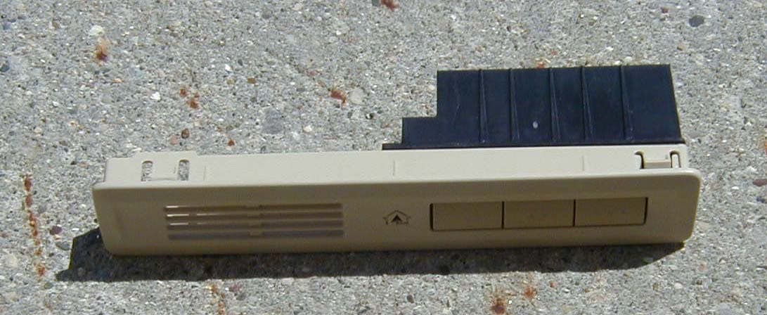
Click to zoom
Application Details
- Equipment Class
- DSR - Part 15 Remote Control/Security Device Transceiver
- Date of Grant
- Jun 13, 2007
- Application Purpose
- Original Equipment
- Date of Application
- Apr 29, 2007
- Equipment Note
- Universal Garage Door Opener
- Frequency Range
- 288.00000000 - 434.00000000
- Country
- United States
Documents & Files
Document Text
Text extracted from the exhibit documents filed with the FCC. Open a document above to read the original.
Users Manual
The Owners Manual for the Homelink® series Universal Garage Door Opener is reproduced here. HomeLink ® Universal Transceiver Suggested Owner’s Manual Text March 2002 HomeLink ® Universal Transceiver The HomeLink ® Universal Transceiver in your vehicle provides a convenient way to replace up to three hand- held transmitters with a single built-in component. This innovative feature will learn the radio frequency codes of most current transmitters used to activate devices such as garage doors, entry door locks, estate gates, security systems, and home or office lighting. For additional information on HomeLink and/or HomeLink compatible products, call 1-800-355-3515 or refer to the HomeLink web site at www.home link.jci.com . Precautions When programming the HomeLink Universal Transceiver to a garage door opener or entry gate, make sure that people and objects are out of the way to prevent potential harm or damage. Do not use the HomeLink Universal Transceiver with any garage door opener that lacks the safety stop and reverse feature as required by federal safety standards. (This includes any garage door opener model manufactured before April 1, 1982.) A garage door opener which cannot detect an object, signaling the door to stop and reverse, does not meet current federal safety standards. Using a garage door opener without these features increases risk of serious injury or death. For more information, call 1-800-355-3515 or on the internet at www.homelink.jci.com. Retain the original transmitter for future programming procedures (i.e., new vehicle purchase). It is also suggested that upon the sale of the vehicle, the programmed HomeLink Universal Transceiver buttons be erased for security purposes (follow step 1 in the “Programming” portion of this text). Programming Note : For best results, replace the battery in the hand-held transmitter with a new battery before programming. If your garage door opener receiver (located in the garage) is equipped with an antenna, make sure the antenna is completely uncoiled and hangs straight down. 1. Press and hold the two outside buttons - releasing only when the indicator light begins to flash after 20 seconds . (This procedure erases the factory set default codes and does not have to be followed to program additional hand-held transmitters.) 2. Hold the end of the hand-held transmitter of the device you wish to train approximately one to three inches away from the HomeLink surface - keeping the indicator light in view. (For placement questions, please contact HomeLink at 1-800-355-3515 or on the internet at www.home link.jci.com. ) 3. Using both hands, simultaneously push the hand-held transmitter button and the desired HomeLink button. Do not re le ase the buttons until ste p 4 has be e n comple te d. Note: Some entry gates and garage door openers may require you to replace this programming step (#3) with the procedures noted in the “Canadian Programming / Gate Programming” section. 4. The HomeLink indicator light will flash, first slowly and then rapidly. When the indicator light flashes rapidly, release both buttons. (The rapid flashing light indicates successful programming of the new frequency signal.) If, after 20 seconds, the indicator light does not flash rapidly, release both the HomeLink and the hand-held transmitter buttons and repeat steps tw o through four. However, position the hand-held transmitter at a different length and/or angle until the indicator light begins to flash rapidly. Release both buttons after the indicator light flashes rapidly. Refer to “Rolling Code Programming” and/or “Canadian Programming/Gate Programming” for additional procedures if necessary. To activate the garage door or other programmed device upon successfully completing the steps above, press and hold the HomeLink button - releasing when the device begins to activate. To program the remaining tw o buttons, follow steps 2 through 4. If you do not successfully program the HomeLink Universal Transceiver to learn the signal of the hand-held transmitter, refer to “Rolling Code Programming” within this text or call toll-free for customer assistance at 1-800- 355-3515 or on the internet at www.home link.jci.com. Canadian Programming / Gate Programming Canadian frequency law s, and the technology of some entry gates, require you to “cycle” (press and re-press the hand- held transmitter button every tw o seconds) during programming. Continue to press and hold the desired HomeLink button (note steps 3 through 5 in the “Programming” portion of this text) w hile you “cycle” your hand-held transmitter until the frequency signal has been learned. The indicator light w ill flash slowly and then rapidly upon successful training. Note: When programming a garage door opener or gate, it is advised to unplug the device during the “cycling” process to prevent possible motor burn-up Operating the HomeLink ® Universal Transceiver To operate, simply press the programmed HomeLink button. Activation will now occur for the trained product (garage door, security system, entry door lock, estate gate, or home or office lighting). For convenience, the hand-held transmitter of the device may also be used at any time. Rolling Code Programming Rolling code garage door openers (or other rolling code devices) which are “code protected” and manufactured after 1996, may be determined by the following: A.Reference the garage door opener owner’s manual for verification. B.The hand-held transmitter appears to program the HomeLink Universal Transceiver but HomeLink does not activate the garage door. C.Press and hold the trained HomeLink button. The garage door opener has the rolling code feature if the HomeLink indicator light flashes rapidly and then turns solid after 2 seconds. To train a garage door opener with the rolling code feature, follow these instructions after completing the “Programming” portion of this text (the aid of a second person may make the following training procedures quicker a…
Text truncated - open the document above for the full version.
External Photos
Exterior Photographs Exterior View, Top ¾ View, Showing Buttons and Faceplate Exterior View, Rear Housing
Internal Photos
Interior Photographs Disassembled View Transceiver and Button PCB, Top View Transceiver and Button PCB, Bottom View Homelink RF PCB, Detail View Button and LED Board, Detail View
Test Report
April 20, 2007 Technical Report to the FCC and Industry Canada Regarding Johnson Controls Interiors, L.L.C. Homelink© IV Model: CB2HONACLHL4 FCC ID: CB2HONACHL4 IC:279B-HONACHL4 Emission Designator: 158KL1D 4/20/07 A report concerning approval for Johnson Controls Homelink® model CB2HONACHL4. Please issue grant immediately upon review. Confidentiality applied to the following sections according to 47 CFR 0.459 and RSP-100 section 10: Circuit Block Diagrams, attachment “hl_block_diag.pdf” Theory/Description of Operation “theory_op.pdf” Parts List Tuning Information “tuning.pdf” Schematics attachment “schematics.pdf” Measurements Made by: Measurements Observed by: Bolay Elgersma R. Craig Harder RF Test Site Technician EMC Design Engineer Johnson Controls Interiors, LLC. Johnson Controls Interiors, LLC. Report and Application Prepared by: Bolay Elgersma EMC Design Engineer Johnson Controls Interiors, LLC. Christopher Plank Laboratory Manager Johnson Controls Interiors, LLC. Johnson Controls Interiors, LLC. Page 1 of 24 MODEL/FCC ID: CB2HONACLHL4 April 20, 2007 1. General Information 1.1. Product Description: The Johnson Controls Interiors HomeLink® HL4 Universal Garage Door Opener is a low-power transceiver OEM device that is installed into an overhead area of the automobile. The installation is provided by trained technicians during the course of the manufacture of the automobile. It is powered by the 12 Volt system of the automobile. This Universal Garage Door Opener has the capability to 1. Learn the frequency and bit code format of the user’s existing garage door remote control devices and 2. Reproduce and transmit the frequency and bit code format to remotely operate the user’s garage door. The unit is designed for the periodic operation of a control signal, which typically activates a garage door opener receiver. The unit is supplied to the automobile manufacturer without harness. For testing purposes a typical assembly and 2-conductor cable harness were used to power to the unit. The unit is only operational when the user depresses the control button. It becomes inactive after release of the control button. The three-button HomeLink® unit replaces up to three hand-held transmitters. In addition to the typical operation of the garage door, the unit will learn the radio frequency codes of other transmitter types to activate entry door locks, estate gates, security systems, and home or office lighting. The antenna system is an integral part of the unit. It cannot be altered nor replaced by the user. Service of this system is only available from the Automobile Manufacturer’s Dealerships and Johnson Controls Interiors, LLC. 1.2. Related Grants None. Johnson Controls Interiors, LLC. Page 2 of 24 MODEL/FCC ID: CB2HONACLHL4 1.3. Test Methodology Radiated Emissions testing was done according to ANSI C63.4-2003. The power source for this product is a 12V automotive vehicle battery, thus conducted emissions measurements are not required. The unit is supplied to the automobile manufacturer without harness. For testing purposes a 2-conductor cable harness was used to interface to the unit. April 20, 2007 1.4. Test Facility The Open Area Test Site where these measurements were taken, is located on the grounds of Johnson Controls Automotive Interiors System’s Edgar D. Prince Technical Campus, in the city of Holland, county of Ottawa, state of Michigan, United States of America. The site is a fully enclosed 10m weather-protected OATS. All structure materials above the conducting ground-plane are non-metallic and consist of: wood, laminated lumber, fiberglass, glue, plastic, or fiberglass reinforced plastic. The site contains a 15-foot diameter turntable capable of supporting large cars and light trucks under test. Tabletop testing was conducted on a smaller 3m turntable described in the site recertification report. The test site has been fully described in a reports filled with the FCC and Industry Canada. The report filled with the FCC is dated December 16 2005, was accepted by the FCC in a letter dated December, 28 2005. The report filled with Industry Canada, dated December 15, 2005, was accepted via a letter dated December 28, 2005 . The site was re-certified with the FCC on December 28, 2005 and with the IC on December 28, 2005. Our OATS is registered with the IC under file number IC# 3593. 1.5. Accreditation The Johnson Controls, Inc. - Electronics Validation Lab is accredited to ISO 17025 by the American Association for Laboratory Accreditation (A2LA). Our laboratory scope and accreditation certificate (# 1425.02) are available from their web site www.a2la.org. Our scope of accreditation covers ANSI C63.4 Radiated Emissions at 3m, FCC 47 CFR Part 15, and IC RSS-210. 2. Product Labeling The FCC Identifier assigned is FCC ID: CB2HONACHL4. The Industry Canada certification number is 279B-HONACHL4. These identifiers will be embossed on the product housing. The label will be placed on the exterior of the HL4 housing using an acrylic adhesive that will permanently affix the label. Because of the small size of the device and because the installation is inside a portion of the automobile, the following statements will appear in the user’s manual. Refer to attachment “user_man.pdf” for the entire text of the user’s manual. “This device complies with Part 15 of the FCC rules and with RSS-210 of the Industry Canada. Operation is subject to the following two conditions: (1) This device may not cause harmful interference, (2) This device must accept any interference that may be received including interference that may cause undesired operation. WARNING: The transmitter has been tested and complies with FCC and Industry Canada rules. Changes or modifications not expressly approved by the party responsible for the compliance could void the user’s authority to operate the device.” 2.1. Label Drawing and Location on Product. The label drawing is included in the “label.pdf” attachment. A drawing showing the lo…
Text truncated - open the document above for the full version.
Test Setup Photos
Test Setup Photographs Radiated Emissions measurements presented in the report were made in accordance with ANSI C63.4 Figure 9(c). The EUT was placed on a 1 x 1.5m non-metallic table elevated 80cm above a conducting ground plane. The harness was run to the long edge of the table and dropped to a power supply sitting at base of the table. Test Setup - Turntable Test Setup – End View Test Setup – Side View Test Setup – Top View
Contact Information
Applicant
Rick Markiewicz(Electronics Engineering Manager)
Test Firm
Johnson Controls Interiors LLCEdward Thomsen
Technical Specifications
| # | Rule Parts | Frequency Range | Power Output |
|---|---|---|---|
| 1 | 15.231 | 288 MHz - 434 MHz | - |
Other Applications from Johnson Controls Interiors L.L.C.

CB2-BLUE15M-TCU
Mar 20, 2014Automotive Telematics Module with Handsfree Bluetooth
Equipment Class
DSS - Part 15 Spread Spectrum Transmitter
CB2-BLUE15M
Jan 19, 2014Bluetooth Telematics Device
Equipment Class
DSS - Part 15 Spread Spectrum Transmitter
CB262932
Jul 15, 2013Automotive Electronics Infotainment Head Unit with Bluetooth and WLAN
Equipment Class
DTS - Digital Transmission System
CB2775AHL5
Apr 29, 2013Universal Garage Door Opener w/ FHSS TX
Equipment Class
DSR - Part 15 Remote Control/Security Device Transceiver
CB2440AHL5
Feb 24, 2013Universal Garage Door TX w/ FHSS TX
Equipment Class
DSS - Part 15 Spread Spectrum Transmitter