CB2MAZGEN6HFTMazda Blue Tooth HandsFree
Johnson Controls Interiors L.L.C.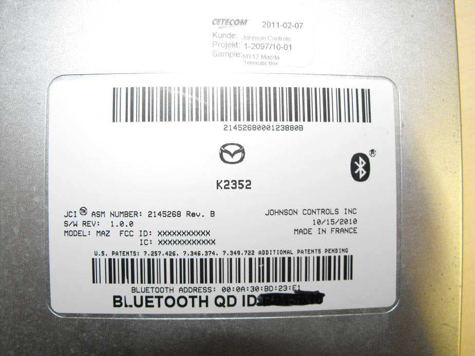
Click to zoom
Application Details
- Equipment Class
- DSS - Part 15 Spread Spectrum Transmitter
- Date of Grant
- Dec 12, 2011
- Application Purpose
- Original Equipment
- Date of Application
- Dec 12, 2011
- Equipment Note
- Mazda Blue Tooth HandsFree
- Frequency Range
- 2402.00000000 - 2480.00000000
- Country
- United States
Documents & Files
Document Text
Text extracted from the exhibit documents filed with the FCC. Open a document above to read the original.
Users Manual
Black plate (223,1) Antenna í qType A The antenna is incorporated into the window glass. CAUTION When washing the inside of the window which has an antenna, use a soft cloth dampened in lukewarm water, gently wiping the antenna lines. Use of glass cleaning products could damage the antenna. qType B Operating Tips for Audio System WARNING Always adjust the audio while the vehicle is stopped: Do not adjust the audio control switches while driving the vehicle. Adjusting the audio while driving the vehicle is dangerous as it could distract your attention from the vehicle operation which could lead to a serious accident. Even if the audio control switches are equipped on the steering wheel, learn to use the switches without looking down at them so that you can keep your maximum attention on the road while driving the vehicle. CAUTION For the purposes of safe driving, adjust the audio volume to a level that allows you to hear sounds outside of the vehicle including car horns and particularly emergency vehicle sirens. NOTE l To prevent the battery from being discharged, do not leave the audio system on for a long period of time when the engine is not running. l If a cellular phone or CB radio is used in or near the vehicle, it could cause noise to occur from the audio system, however, this does not indicate that the system has been damaged. Interior Features Audio System 5-13 í Some models. CX-5_8CA6-EC-11L_Edition1 Page223 Monday, December 12 2011 11:32 AM Form No.8CA6-EC-11L Black plate (224,1) Do not spill any liquid on the audio system. Do not insert any objects, other than CDs, into the slot. qRadio Reception AM characteristics AM signals bend around such things as buildings or mountains and bounce off the ionosphere. Therefore, they can reach longer distances than FM signals. Because of this, two stations may sometimes be picked up on the same frequency at the same time. Station 2 Station 1 Ionosphere FM characteristics An FM broadcast range is usually about 40―50 km (25―30 miles) from the source. Because of extra coding needed to break the sound into two channels, stereo FM has even less range than monaural (non-stereo) FM. FM Station 40—50km (25—30 miles) Signals from an FM transmitter are similar to beams of light because they do not bend around corners, but they do reflect. Unlike AM signals, FM signals cannot travel beyond the horizon. Therefore, FM stations cannot be received at the great distances possible with AM reception. AM wave FM wave FM wave 100—200 km (60—120 miles) Ionosphere Atmospheric conditions can also affect FM reception. High humidity will cause poor reception. However, cloudy days may provide better reception than clear days. 5-14 Interior Features Audio System CX-5_8CA6-EC-11L_Edition1 Page224 Monday, December 12 2011 11:32 AM Form No.8CA6-EC-11L Black plate (225,1) Multipath noise Since FM signals can be reflected by obstructions, it is possible to receive both the direct signal and the reflected signal at the same time. This causes a slight delay in reception and may be heard as a broken sound or a distortion. This problem may also be encountered when in close proximity to the transmitter. Reflected wave Direct Flutter/Skip noise Signals from an FM transmitter move in straight lines and become weak in valleys between tall buildings, mountains, and other obstacles. When a vehicle passes through such an area, the reception conditions may change suddenly, resulting in annoying noise. Weak signal noise In suburban areas, broadcast signals become weak because of distance from the transmitter. Reception in such fringe areas is characterized by sound breakup. Strong signal noise This occurs very close to a transmitter tower. The broadcast signals are extremely strong, so the result is noise and sound breakup at the radio receiver. Station drift noise When a vehicle reaches the area of two strong stations broadcasting at similar frequencies, the original station may be temporarily lost and the second station picked up. At this time there will be some noise from this disturbance. Station 2 88.3 MHz Station 1 88.1 MHz Interior Features Audio System 5-15 CX-5_8CA6-EC-11L_Edition1 Page225 Monday, December 12 2011 11:32 AM Form No.8CA6-EC-11L Black plate (226,1) qOperating Tips for CD Player Condensation phenomenon Immediately after turning on the heater when the vehicle is cold, the CD or optical components (prism and lens) in the CD player may become clouded with condensation. At this time, the CD will eject immediately when placed in the unit. A clouded CD can be corrected simply by wiping it with a soft cloth. Clouded optical components will clear naturally in about an hour. Wait for normal operation to return before attempting to use the unit. Handling the CD player The following precautions should be observed. l The CD revolves at high speed within the unit. Defective (cracked or badly bent) CDs should never be used. l Do not use non-conventional discs such as heart-shaped, octagonal discs, etc. The disc may not eject resulting in a malfunction. l If the memory portion of the CD is transparent or translucent, do not use the disc. Transparent l A new CD may have rough edges on its inner and outer perimeters. If a disc with rough edges is used, proper setting will not be possible and the CD player will not play the CD. In addition, the disc may not eject resulting in a malfunction. Remove the rough edges in advance by using a ball- point pen or pencil as shown below. To remove the rough edges, rub the side of the pen or pencil against the inner and outer perimeter of the CD. l When driving over uneven surfaces, the sound may jump. 5-16 Interior Features Audio System CX-5_8CA6-EC-11L_Edition1 Page226 Monday, December 12 2011 11:32 AM Form No.8CA6-EC-11L Black plate (227,1) l The CD player has been designed to play CDs bearing the identification logo as shown below. No other discs can be played. l Use discs that have been legitimately produced. If illegally-copied discs su…
Text truncated - open the document above for the full version.
External Photos
Test report no.: 1-2097-01-07/10 2011-03-23 Page 70 of 77 An ne x B E x te rna l ph ot ogra phs o f the E UT Photo documentation: Photo 1: (conducted sample) Photo 2: Test report no.: 1-2097-01-07/10 2011-03-23 Page 71 of 77 Photo 3: Photo 4: (radiated sample) Test report no.: 1-2097-01-07/10 2011-03-23 Page 72 of 77 Photo 5: Photo 6:
Internal Photos
Test report no.: 1-2097-01-07/10 2011-03-23 Page 73 of 77 An ne x C Inte r na l p ho to gra phs o f the E UT Photo 1: (conducted sample) Photo 2: (radiated sample) Test report no.: 1-2097-01-07/10 2011-03-23 Page 74 of 77 Photo 3: Photo 4: Test report no.: 1-2097-01-07/10 2011-03-23 Page 75 of 77 Photo 5: Photo 6: Test report no.: 1-2097-01-07/10 2011-03-23 Page 76 of 77 Photo 7: Photo 8:
Test Report
2011-07-25 Page 1 of 68 TEST REPORT Test report no.: 1-2097-01-07/10-A Testing laboratory Applicant CETECOM ICT Services GmbH Untertuerkheimer Strasse 6 – 10 66117 Saarbruecken / Germany Phone: + 49 681 5 98 - 0 Fax: + 49 681 5 98 - 9075 Internet: http://www.cetecom.com e-mail: [email protected] Accredited test laboratory: The test laboratory (area of testing) is accredited according to DIN EN ISO/IEC 17025 DAR registration number: DGA-PL-176/94-D1 Area of Testing: Radio/Satellite Communications Johnson Controls Inc. 915 East 32nd Street, Dock #20 Holland, MI 49423 / USA Phone: +1 616 394 6597 Contact: Patrick Glaser e-mail: [email protected] Phone: +01 616 394 6318 Manufacturer Johnson Controls Inc. 915 East 32nd Street, Dock #20 Holland, MI 49423 / USA Test standard/s 47 CFR Part 15 Title 47 of the Code of Federal Regulations; Chapter I Part 15 - Radio frequency devices RSS - 210 Issue 8 Spectrum Management and Telecommunications - Radio Standards Specification Low-power Licence-exempt Radiocommunication Devices (All Frequency Bands): Category I Equipment For further applied test standards please refer to section 3 of this test report. Test item Kind of test item : Telematic Box with Bluetooth Model name : Mazda_Gen_6_HFT FCC ID : CB2-MAZGEN6HFT IC : 279B-MAZGEN6HFT Frequency : ISM band 2400 – 2483.5 MHz (Lowest channel 2402 MHz – highest channel 2480 MHz) Power supply : 13.5 V DC Temp. range : -30 °C to 85 °C This test report is electronically signed and valid without handwriting signature. For verification of the electronic signatures, the public keys can be requested at the testing laboratory. Test performed: Test report authorised: p. o. Joerg Warken Marco Bertolino Test report no.: 1-2097-01-07/10-A 2011-07-25 Page 2 of 68 1 Table of contents 1 Table of contents ............................................................................................................................................ 2 2 General information ....................................................................................................................................... 3 2.1 Notes ..................................................................................................................................................... 3 2.2 Application details ............................................................................................................................... 3 3 Test standard/s ............................................................................................................................................... 3 4 Test environment ............................................................................................................................................ 3 5 Test item .......................................................................................................................................................... 4 6 Test laboratories sub-contracted ................................................................................................................. 4 7 Summary of measurement results ............................................................................................................... 5 8 RF measurement testing................................................................................................................................ 6 8.1 Description of test setup .................................................................................................................... 6 8.1.1 Radiated measurements............................................................................................................. 6 8.1.2 Conducted measurements.......................................................................................................... 7 8.2 Additional comments .......................................................................................................................... 7 8.3 RSP100 test report cover sheet / performance test data ................................................................ 8 9 Measurement results ...................................................................................................................................... 9 9.1 Antenna gain ........................................................................................................................................ 9 9.2 Power spectral density ..................................................................................................................... 10 9.3 Carrier frequency separation ........................................................................................................... 11 9.4 Number of hopping channels ........................................................................................................... 13 9.5 Time of occupancy (dwell time) ....................................................................................................... 15 9.6 Spectrum bandwidth of a FHSS system – 20 dB bandwidth ........................................................ 16 9.7 Maximum output power .................................................................................................................... 22 9.8 Band edge compliance conducted .................................................................................................. 29 9.9 Band edge compliance radiated ...................................................................................................... 36 9.10 TX spurious emissions conducted .............................................................................................. 43 9.11 TX spurious emissions radiated................................................................................................... 50 9.12 RX spurious emissions radiated .................................................................................................. 59 9.13 TX spurious emissions radiated < 30 MHz ...........................................…
Text truncated - open the document above for the full version.
Test Setup Photos
Test report no.: 1-2097-01-07/10 2011-03-23 Page 68 of 77 An ne x A P ho tog ra phs o f t h e te s t s e tu p Photo documentation: Photo 1: Photo 2: Test report no.: 1-2097-01-07/10 2011-03-23 Page 69 of 77 Photo 3:
Contact Information
Applicant
Rick Markiewicz(Electronics Engineering Manager)
Test Firm
cetecom advanced GmbHGerald Schmidt
Technical Specifications
| # | Rule Parts | Frequency Range | Power Output |
|---|---|---|---|
| 1 | 15C | 2.40 GHz - 2.48 GHz | 1.30 mW |
Other Applications from Johnson Controls Interiors L.L.C.

CB2-BLUE15M-TCU
Mar 20, 2014Automotive Telematics Module with Handsfree Bluetooth
Equipment Class
DSS - Part 15 Spread Spectrum Transmitter
CB2-BLUE15M
Jan 19, 2014Bluetooth Telematics Device
Equipment Class
DSS - Part 15 Spread Spectrum Transmitter
CB262932
Jul 15, 2013Automotive Electronics Infotainment Head Unit with Bluetooth and WLAN
Equipment Class
DTS - Digital Transmission System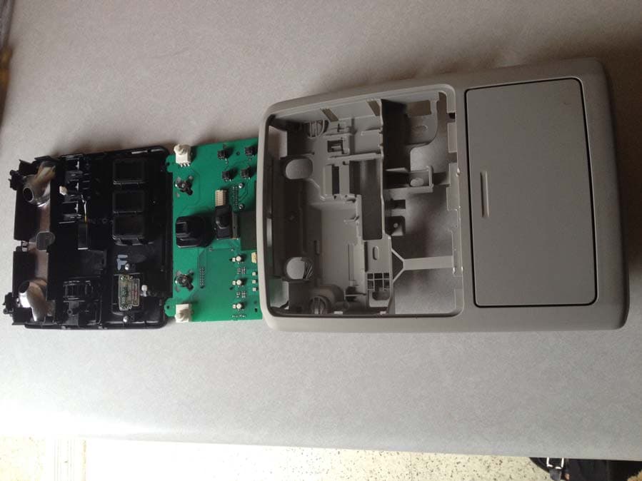
CB2775AHL5
Apr 29, 2013Universal Garage Door Opener w/ FHSS TX
Equipment Class
DSR - Part 15 Remote Control/Security Device Transceiver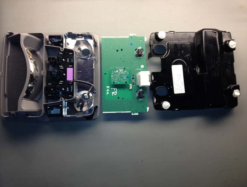
CB2440AHL5
Feb 24, 2013Universal Garage Door TX w/ FHSS TX
Equipment Class
DSS - Part 15 Spread Spectrum Transmitter