CB2UCONNAutomotive Bluetooth Hands-Free Interface
Johnson Controls Interiors L.L.C.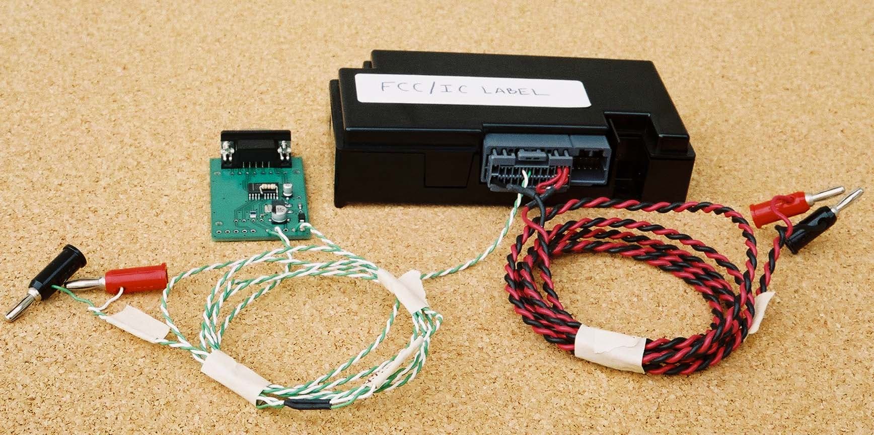
Click to zoom
Application Details
- Equipment Class
- DSS - Part 15 Spread Spectrum Transmitter
- Date of Grant
- Oct 23, 2002
- Application Purpose
- Original Equipment
- Date of Application
- Oct 23, 2002
- Equipment Note
- Automotive Bluetooth Hands-Free Interface
- Frequency Range
- 2402.00000000 - 2480.00000000
- Country
- United States
Documents & Files
Document Text
Text extracted from the exhibit documents filed with the FCC. Open a document above to read the original.
Users Manual
Hands-Free Module Hands-Free Telephone Interface Sample Chrysler User Guide Text User Guide Number CT-ELE-002-Preliminary Johnson Controls, Inc. Automotive Systems Group Interiors Electronics One Prince Center Holland, MI 49423 Note: This document is a Johnson Controls, Inc. confidential document. Disclosure must be controlled by the recipient. Copyright Notice This manual is the property of Johnson Controls Incorporated and is for the exclusive use of its employees or assignees. Its contents are not to be disclosed to outside parties without the permission of Johnson Controls Incorporated. No part of this manual may be reproduced in any form whatsoever, without the permission of Johnson Controls Incorporated. Note: This document is a Johnson Controls Incorporated confidential document. Disclosure must be controlled by the recipient. 2002 Johnson Controls Interiors. All rights reserved. Trademarks Bluetooth ™ is a trademark owned by the Bluetooth SIG, Inc. Other product names and company names found in this manual may be the trademarks of their respective holders. User Manual Release Approval Core Product Lead Engineer: Date: Revisions Version Date Description Who Preliminary July 17, 2002 Preliminary Kevin Haisch/Rich Jansma Johnson Controls, Inc. Automotive Systems Group Interiors Electronics One Prince Center Holland, MI 49423 i Table of Contents Introduction.........................................................................................................1 Precautions..........................................................................................................1 Setting up Your HFM.........................................................................................1 Pairing..............................................................................................................1 Clearing Paired Phones................................................................................1 Using Your HFM..................................................................................................2 Voicetags.........................................................................................................2 Answering an Incoming Call.........................................................................3 Making a Call..................................................................................................3 Dialing a Number Directly.......................................................................3 Dialing a Number with Voicetags...........................................................4 Using Call Waiting..........................................................................................4 Using Barge In................................................................................................4 Adjusting Volume...........................................................................................5 Terminating a Phone Call.............................................................................5 Index......................................................................................................................6 This Page Intentionally Left Blank 1 Introduction The Hands Free Module (HFM) is a Bluetooth ™ device that allows for wireless communication with other Bluetooth devices. Bluetooth wireless technology is a high frequency radio link that allows two Bluetooth devices to exchange audio information and data at high speed. Because of the versatility of Bluetooth wireless technology, enabled devices do not share all of the same "profiles." To ensure that your phone will be compatible with your HFM, be sure to purchase a cellular phone that supports the "Dial-up Networking" profile. Precautions Warning: When preparing to set up the HFM, be sure the vehicle involved is in park with the engine turned off. Setting up Your HFM Note: Most vehicles require the ignition switch to be turned to the second (or "accessory") position for programming and/or operation of the HFM. The radio must be turned on to hear HFM audio. It is also recommended that your cell phone's battery be fully charged to ensure that the Bluetooth connection will be established with minimal difficulty. To use the voice recognition software, face the windshield and speak clearly in your normal voice (do not shout). Note: The voice recognition software expects you to speak in a natural voice. Do not try to "help" the voice recognition software by speaking slowly or by pronouncing words more distinctly than you normally do. Pairing In order for your HFM to work with your Bluetooth phone, you must first pair the two devices. To pair a phone to HFM: 1. Press and release HFM's Phone button. 2. After you hear the "Ready" prompt, say "Setup, Registration." 3. The HFM will prompt, "Do you want to register a phone, clear a phone, or list available phones?" Say "Register." 4. Refer to your cellular phone user's manual for further information on pairing your phone to HFM. Clearing Paired Phones To re-prioritize the cell phones being used, you must first clear the phone(s) paired with HFM. Note: If you make a mistake during the clearing process or decide not to clear a phone, press either HFM's Phone button or VR button to exit the clearing mode. To clear paired cell phones from the HFM's memory: 1. Press and release HFM's Phone button. 2. After you hear the "Ready" prompt, say "Setup, Registration." 2 3. The HFM will prompt, "Do you want to register a phone, clear a phone, or list available phones?" Say "Clear." 4. The HFM will prompt, "Which phone would you like to clear or say all to clear all phones?" 5. Say the phone's voicetag (such as "Rich's Phone") to clear one phone or say "All" to clear all paired phones. 6. The HFM responds with "Removing all, is this correct?" if you chose to clear all phones or it responds with "Removing Rich's Phone, is this correct?" if you chose to clear an individual phone (such as Rich's Phone). 7. Say "Yes". The HFM responds with "C…
Text truncated - open the document above for the full version.
Block Diagram
Cotulla Bluetooth Baseband and Transciever BCM2033 Project Iceland Bluetooth Transient Protection Power Regulation Power Supply 1.8V,3.3V Ignition Audio J1850 Micro-Controller Bluetooth Antenna 15.36 MHz Crystal Standard UART GPIO[46,47] Audio MUX Audio Out (L /R) Flash 8MByte 2 - (4M x 16) RAM 16MByte 2 - (8M x 16) Fully Functional UART GPIO[34,39] BT UART GPIO[42-45] AC97 Interface 57600 kb/s CS4299 AC-97 CODEC AC-Link SSP GPIO[23-27] Audio In (L /R) Audio Out (L /R) Audio In (L /R) Vehicle Audio I/F 3.3V, 5V Battery I2C IDR J1850 Tester Comm Port 1.0V,3 .3V 2-button User's Interface Mic 2 In Reverse Lockout DSP1627 ROM CSP1027 CODEC 8kHz 16-bit PCM Mic 1 In 8kHz 16bit PCM 19200kb/s Model Year 2003.5 Mirror Power
Cover Letter(s)
Re:Certification for JCI U-connect Transmitter Model: U-connect FCC ID: CB2UCONN IC: 279B-UCONN REQUEST FOR CONFIDENTIALITY Pursuant to 47 CRF 0.459, JCI requests that a part of the subject application be held confidential. This comprises Exhibits (5) Schematics (10)Parts List (Part of Exhibit only) JCI has spent substantial effort in developing this product and it is one of the first of its kind in industry. Having the subject information easily available to "competition" would negate the advantage they have achieved by developing this product. Not protecting the details of the design will result in financial hardship. If there are any questions regarding this request, please contact me at the above address or call 734-483-4211, fax 734-647-2106 or e-mail [email protected]. Sincerely, Valdis V. Liepa Research Scientist University of Michigan October 4, 2002 Re:Certification for JCI U-connect Transmitter Model: U-connect FCC ID: CB2UCONN IC: 279B-UCONN STATEMENT OF MODIFICATIONS There were no modifications made to the DUT by this test laboratory. (Also see Section 3.1 of the attached Test Report). _____________________ Valdis V. Liepa Research Scientist Re:Certification for JCI U-connect Transmitter Model: U-connect FCC ID: CB2UCONN IC: 279B-UCONN GENERAL PRODUCT INFORMATION The device, for which certification is pursued, has been designed by: Johnson Controls Interiors L.L.C. 279B-UCONN One Prince Center Holland, MI 49423 Craig Harder Tel:616-394-6101 Fax:616-394-3877 It will be manufactured by: Jabil Circuits, Inc 1700 Atlantic Blvd. Auburn Hills, MI 48326 Tel:248-391-5300 Fax:248-391-5317 Canadian Contact: Jim Komar Quality Manager Lakeshore Plant 477 Jutras Drive South Tecumseh, ON N8N 5C4 Re:Certification for JCI U-connect Transmitter Model: U-connect FCC ID: CB2UCONN IC: 279B-UCONN POWER OF ATTORNEY A letter granting Valdis V. Liepa the Power of Attorney is on file and can be provided when so requested.
Cover Letter(s)
ATCB RE: Johnson Controls Interiors L.L.C. FCC ID: CB2UCONN The following is in response to the comments provided for the CB2UCONN filing. 1) Please provide a photograph that shows the complete back of the Bluetooth TX board. An Addendum to the Internal Photos test exhibit has been uploaded. 2) Please provide an updated label that includes the correct FCC ID for this application. An updated label has been uploaded. 3) The device appears to contain 2 or 3 different boards. Please provide a description of what each board is. The DUT includes two PCB boards. The primary board contains the Bluetooth transmitter and additional digital circuitry which connects the DUT to the automotive buss. The smaller secondary board contains the digital electronics which control the Bluetooth coding and decoding operations. 4) Please provide radiated spurious emissions test photographs. A test photograph of the radiated emissions setup is already available in the Test Setup Photos exhibit. 5) Please provide a separate RF exposure exhibit. Please be sure to include information regarding how the device is expected to be mounted within a car and the distance the antenna is from users once installed. Also, please provide MPE calculations as these are still desired even with the low power output. As per conversations with Bill Graff at ATCB about this device, we were told that for a device of EIRP less than 10 mW we would not be required to submit RF exposure calculations as the DUT “operates at substantially low output power levels, with a low gain antenna” as is stated in the Public Notice on Filing and Measurement Guidelines for FHSS Systems you forwarded to use with this request. If this is incorrect please let us know for future reference. We have uploaded a RF Exposure exhibit if it is still deemed necessary. 6) The users manual provided contains statements regarding confidentiality. Please note that the users manual is not typically allowed to be considered confidential, since the end user is expected to receive a copy anyway. Please comment. Disregard the Confidentiality statement in the User’s Manual. 7) Section 6.4 shows data and a limit for a 1 second. Please note that the limit specified is over a 30 second period of time. Please adjust the data given in this section. Additionally, depending on the amount of data the unit is sending, it likely will not transmit full packets and will provide data less than expected. Refer to Theory of operation that we sent to you earlier. This has been corrected. See the revised test report we have included. 8) Section 6.5 & 6.6 of the test report states that average measurements were made using a 1 Hz VBW. The FCC only accepts an average measurement of 10 Hz or greater. Additionally, average measurements with the hopping enabled are NOT allowed. To obtain an average measurement, the following must be employed: 1) Measure the signal with hopping DISABLED using RBW = 1 MHz, VBW = 10 Hz. 2) Determine worse case duty cycle in any 100 msec of time. Please note that Bluetooth offers several different length packets depending on amount of data to send. Subtract the correction factor of 20 log (maximum transmit time in 100 msec/100) from 1) above. A 1Hz VBW was a typo in section 6.5 of the test report. All average data was taken with 100 Hz VBW as stated in section 6.6. This has been corrected in the revised test report. 9) The EUT should NOT be hopping for power measurements. Please provide new peak data (with hopping disabled and also for a typical low, middle, and high channels) for section 6.6 of the test report and also adjust the 731 form if necessary. Additionally, we have provided a document regarding testing of FHSS devices that you may find useful. Please note outline areas of document regarding hoping or being hop stopped. The power levels for the device in non-hopping mode have been included in the revised test report. Note there was no change in output power levels from the DUT. 10) The EUT should NOT be hopping for RF Antenna Conducted measurements. Please provide new peak data (with hopping disabled and also for a typical low, middle, and high channels) for section 6.6 of the test report. This has been corrected. See the revised test report we have included. 11) Bandedge compliance should be measured for both a hopping and non-hopping mode of operation. Please provide new data for the bandege that checks both modes of operation. This has been corrected. See the revised test report we have included.
Cover Letter(s)
ATCB RE: CB2UCONN The following is in response to your request for further information regarding the submission/certification of FCC ID: CB2UCONN. 1) The RF exposure calculations provided show an antenna gain of 1 dBi, while section 6.7 of the test report state an antenna gain 0 dBi. Please correct the exhibits to be consistent. This has been corrected. Please see updated Test Report. 2) The RF exposure calculations should be shown for the highest output power. Please correct this exhibit for the output power of 4.7 dBm (2.95 mW). This has been corrected. Please see updated RF Exposure exhibit. 3) Please note that the Duty Cycle presented in the report was based on your measurements. However Bluetooth has different packet lengths that may be used in modes with longer packets. The theory of operation for Bluetooth states that their may be 1, 3, or 5 slots used per transmit depending on the mode of operation. For a DH1 packet the TX is on 0.625 us per 49 mS per channel, while for a DH5 packet the TX is on 0.625 * 5 per 247 ms per channel. These duty cycles equal the following: 20 log (.625/49) = 37.9 dB or 20 log (3.125/100) = -30 dB. All are greater than the 20 dB difference between the peak and average limits. However, since average measurements where not made and you are relying on this justification, it is recommended that reference to this fact that all types of transmissions in Bluetooth yield a correction factor > 20 dB. A reference to the statement included in the attestations portion of the filing has been included in the revised test report. 4) Your response stated that for antenna conducted measurements was included in the new revision of the report for a low, middle, and high channel. However, section 6.9 of the Test report states that the hopping was enabled and data was provided for all channels. This has been corrected. Please see updated Test Report.
Cover Letter(s)
American Telecommunications Certification Body Inc. 6731 Whittier Ave, McLean, VA 22101 October 16, 2002 RE: Johnson Controls Interiors L.L.C. FCC ID: CB2UCONN After a review of the submitted information, I have a few comments on the above referenced Application. 1) Please provide a photograph that shows the complete back of the Bluetooth TX board. 2) Please provide an updated label that includes the correct FCC ID for this application. 3) The device appears to contain 2 or 3 different boards. Please provide a description of what each board is. 4) Please provide radiated spurious emissions test photographs. 5) Please provide a separate RF exposure exhibit. Please be sure to include information regarding how the device is expected to be mounted within a car and the distance the antenna is from users once installed. Also, please provide MPE calculations as these are still desired even with the low power output. 6) The users manual provided contains statements regarding confidentiality. Please note that the users manual is not typically allowed to be considered confidential, since the end user is expected to receive a copy anyway. Please comment. 7) Section 6.4 shows data and a limit for a 1 second. Please note that the limit specified is over a 30 second period of time. Please adjust the data given in this section. Additionally, depending on the amount of data the unit is sending, it likely will not transmit full packets and will provide data less than expected. Refer to Theory of operation that we sent to you earlier. 8) Section 6.5 & 6.6 of the test report states that average measurements were made using a 1 Hz VBW. The FCC only accepts an average measurement of 10 Hz or greater. Additionally, average measurements with the hopping enabled are NOT allowed. To obtain an average measurement, the following must be employed: 1) Measure the signal with hopping DISABLED using RBW = 1 MHz, VBW = 10 Hz. 2) Determine worse case duty cycle in any 100 msec of time. Please note that Bluetooth offers several different length packets depending on amount of data to send. Subtract the correction factor of 20 log (maximum transmit time in 100 msec/100) from 1) above. 9) The EUT should NOT be hopping for power measurements. Please provide new peak data (with hopping disabled and also for a typical low, middle, and high channels) for section 6.6 of the test report and also adjust the 731 form if necessary. Additionally, we have provided a document regarding testing of FHSS devices that you may find useful. Please note outline areas of document regarding hoping or being hop stoped. 10) The EUT should NOT be hopping for RF Antenna Conducted measurements. Please provide new peak data (with hopping disabled and also for a typical low, middle, and high channels) for section 6.6 of the test report. 11) Bandedge compliance should be measured for both a hopping and non-hopping mode of operation. Please provide new data for the bandege that checks both modes of operation. Timothy R. Johnson Examining Engineer Direct Phone: 404-414-8071 mailto: [email protected] The items indicated above must be submitted before processing can continue on the above referenced application. Failure to provide the requested information may result in application termination. Correspondence should be considered part of the permanent submission and may be viewed from the Internet after a Grant of Equipment Authorization is issued. Please do not respond to this correspondence using the email reply button. In order for your response to be processed expeditiously, you must submit your documents through the AmericanTCB.com website. Also, please note that partial responses increase processing time and should not be submitted. Any questions about the content of this correspondence should be directed to the sender.
Cover Letter(s)
American Telecommunications Certification Body Inc. 6731 Whittier Ave, McLean, VA 22101 October 24, 2002 RE: Johnson Controls Interiors L.L.C. FCC ID: CB2UCONN After a review of the submitted information, I have a few comments on the above referenced Application. 1) The RF exposure calculations provided show an antenna gain of 1 dBi, while section 6.7 of the test report state an antenna gain 0 dBi. Please correct the exhibits to be consistent. 2) The RF exposure calculations should be shown for the highest output power. Please correct this exhibit for the output power of 4.7 dBm (2.95 mW). 3) Please note that the Duty Cycle presented in the report was based on your measurements. However Bluetooth has different packet lengths that may be used in modes with longer packets. The theory of operation for Bluetooth states that their may be 1, 3, or 5 slots used per transmit depending on the mode of operation. For a DH1 packet the TX is on 0.625 us per 49 mS per channel, while for a DH5 packet the TX is on 0.625 * 5 per 247 ms per channel. These duty cycles equal the following: 20 log (.625/49) = 37.9 dB or 20 log (3.125/100) = -30 dB. All are greater than the 20 dB difference between the peak and average limits. However, since average measurements where not made and you are relying on this justification, it is recommended that reference to this fact that all types of transmissions in Bluetooth yield a correction factor > 20 dB. 4) Your response stated that for antenna conducted measurements was included in the new revision of the report for a low, middle, and high channel. However, section 6.9 of the Test report states that the hopping was enabled and data was provided for all channels. Timothy R. Johnson Examining Engineer Direct Phone: 404-414-8071 mailto: [email protected] The items indicated above must be submitted before processing can continue on the above referenced application. Failure to provide the requested information may result in application termination. Correspondence should be considered part of the permanent submission and may be viewed from the Internet after a Grant of Equipment Authorization is issued. Please do not respond to this correspondence using the email reply button. In order for your response to be processed expeditiously, you must submit your documents through the AmericanTCB.com website. Also, please note that partial responses increase processing time and should not be submitted. Any questions about the content of this correspondence should be directed to the sender.
Operational Description
BlueConnect Theory of Operation The BlueConnect module is a hands-free interface to Bluetooth enabled devices. By connecting to the vehicle bus and radio, the user is able to interact with a fully vehicle integrated system from the OEM. A voice recognition engine allows the user to control the system throughout a variety of functions. Interaction with the voice recognizer is accomplished via a microphone mounted in a manufacturer-chosen location. Further user interface (switches and voice recognizer) details are specific to the manufacturer’s preference. The primary processor of the system runs the voice recognizer as well as general function manager. The general function manager calls other functions as necessary based upon feedback from the vehicle bus, the user (via voice recognition and/or the button interface), or Bluetooth and the connected Bluetooth device(s). Memory, composed of separate RAM and FLASH, allow for reprogramming and upgrades of the system as new features are developed. The memory is also used for voice recognition libraries and other Bluetooth devices that have been paired to the system. Other user-specific features and configurations are saved here as well. A Bluetooth link to paired devices is used for the audio gateway through the system. By using the Bluetooth protocol, the module is able to connect to several different devices and route the audio out to the vehicle radio. The interface to the vehicle radio is configurable for single-ended audio, differential audio, or stereo versions of either configuration.
RF Exposure Info
RF Exposure Limits The following table summarizes the minimum operating distance for this device as calculated from FCC OET Bulletin 65. Potential Health Hazard Radiation Level Ant. Ant. Gain (dB) Po (mW) EIRP (mW) R (cm) PCB 1 2.95 3.71 0.54 The following equations were used in calculating the operating distance (R). 10 )( 10)()( dBGain mWPomWEIRP⋅= and )/(4 )( 2 cmmWS mWEIRP R ⋅Π⋅ =, S = 1mW/cm 2
Test Report
1 The University of Michigan Radiation Laboratory 3228 EECS Building Ann Arbor, MI 48109-2122 Tel: (734) 764-0500 Measured Radio Frequency Emissions From Johnson Controls Model: U-connect Report No. 137 October 19, 2002 Copyright © 2002 For: Johnson Controls Interiors L.L.C. One Prince Center Holland, MI 49423 Contact: Craig Harder Tel: 616-394-6101 Fax: 616-394-3877 PO: Verbal Tests supervised by: Measurements made by: Report approved by: _____________________ Joseph D. Brunett Valdis V. Liepa Research Scientist Summary Tests for compliance with FCC Regulations, Part 15.247, and with Industry Canada (IC) Regulations, RSS-210, Part 6.2.2, were performed on Johnson Controls model U-connect frequency hopping spread spectrum (FHSS) Bluetooth transmitter. The DUT is subject to the Rules and Regulations as a transmitter. In testing competed on 17-Oct-02, the radiated emissions in restricted bands were met by 11.8 dB. The AC line conducted emissions tests do not apply, since the device is powered from a 12 VDC automotive system. The DUT is exempt as a digital device since it is used in a transportation vehicle. All other testing indicates that the Johnson Controls model U-connect meets the limitations set forth by the FCC and IC for a 2.4 GHz FHSS transmitter. 2 1. Introduction Johnson Controls model U-connect was tested for compliance with FCC Regulations, Part 15, Subpart C, adopted under Docket 87-389, April 18, 1989, and with Industry Canada RSS-210, Issue 5, November, 2001. The tests were performed at the University of Michigan Radiation Laboratory Willow Run Test Range following the procedures described in ANSI C63.4-1992 "Methods of Measurement of Radio- Noise Emissions from Low-Voltage Electrical and Electronic Equipment in the Range of 9 kHz to 40 GHz". The Site description and attenuation characteristics of the Open Site facility are on file with FCC Laboratory, Columbia, Maryland (FCC Reg. No: 91050) and with Industry Canada, Ottawa, ON (File Ref. No: IC 2057). 2. Test Procedure and Equipment Used The pertinent test equipment commonly used in our facility for measurements is listed in Table 2.1 below. The middle column identifies the specific equipment used in these tests. Table 2.1 Test Equipment Test Instrument Eqpt. Used Manufacturer/Model Spectrum Analyzer (0.1-1500 MHz) Hewlett-Packard, 182T/8558B Spectrum Analyzer (9kHz-22GHz) X Hewlett-Packard 8593A SN: 3107A01358 Spectrum Analyzer (9kHz-26GHz) X Hewlett-Packard 8593E, SN: 3412A01131 Spectrum Analyzer (9kHz-26GHz) Hewlett-Packard 8563E, SN: 3310A01174 Spectrum Analyzer (9kHz-40GHz) Hewlett-Packard 8564E, SN: 3745A01031 Power Meter X Hewlett-Packard, 432A Power Meter Anritsu, ML4803A/MP Peak Power Meter Pacific Instruments 1018B Harmonic Mixer (26-40 GHz) Hewlett-Packard 11970A, SN: 3003A08327 Harmonic Mixer (40-60 GHz) Hewlett-Packard 11970U, SN: 2332A00500 Harmonic Mixer (75-110 GHz) Hewlett-Packard 11970W, SN: 2521A00179 Harmonic Mixer (140-220 GHz) Pacific Millimeter Prod., GMA, SN: 26 S-Band Std. Gain Horn X S/A, Model SGH-2.6 C-Band Std. Gain Horn X University of Michigan, NRL design XN-Band Std. Gain Horn X University of Michigan, NRL design X-Band Std. Gain Horn X S/A, Model 12-8.2 X-band horn (8.2- 12.4 GHz) X Narda 640 X-band horn (8.2- 12.4 GHz) Scientific Atlanta , 12-8.2, SN: 730 K-band horn (18-26.5 GHz) X FXR, Inc., K638KF Ka-band horn (26.5-40 GHz) X FXR, Inc., U638A U-band horn (40-60 GHz) Custom Microwave, HO19 W-band horn(75-110 GHz) Custom Microwave, HO10 G-band horn (140-220 GHz) Custom Microwave, HO5R Bicone Antenna (30-250 MHz) X University of Michigan, RLBC-1 Bicone Antenna (200-1000 MHz) X University of Michigan, RLBC-2 Dipole Antenna Set (30-1000 MHz) X University of Michigan, RLDP-1,-2,-3 Dipole Antenna Set (30-1000 MHz) EMCO 2131C, SN: 992 Active Rod Antenna (30 Hz-50 MHz) EMCO 3301B, SN: 3223 Active Loop Antenna (30 Hz-50 MHz) EMCO 6502, SN:2855 Ridge-horn Antenna (300-5000 MHz) X University of Michigan Amplifier (5-1000 MHz) X Avantak, A11-1, A25-1S Amplifier (5-4500 MHz) X Avantak Amplifier (4.5-13 GHz) X Avantek, AFT-12665 Amplifier (6-16 GHz) X Trek Amplifier (16-26 GHz) X Avantek LISN Box University of Michigan Signal Generator Hewlett-Packard 8657B 3 3. Configuration and Identification of Device Under Test The DUT is a frequency hopping spread spectrum (FHSS) transmitter operating in 2400 - 2483.5 MHz band. The DUT is 5 x 1.5 x 3.5 inches, and connects to a peripheral laptop computer via a serial interface card for testing purposes. The system has been designed to operate with 79 channels spaced 1 MHz apart between 2402 MHz and 2480 MHz. The DUT has one antenna built into the PCB. The DUT was designed and manufactured by Johnson Controls Interiors L.L.C., One Prince Center, Holland, MI 49423. It is identified as: Johnson Controls Bluetooth Module Model: U-connect SN: Proto1 FCC ID: CB2UCONN IC: 279B-UCONN In addition to a standard unit, a modified unit was provided by the manufacturer which had the internal antenna disabled and a SMA connector attached for conducted antenna measurement purposes. Peripheral Equipment: Laptop Computer Compaq Presario SN: V745BQD22994 Model: Series 2940 FCC ID: CNTTAI-24639-TT-E Serial Interface Card SN: Proto1 3.1 EMI Relevant Modifications No modifications were made to the DUT by this laboratory during testing. 4 4. Emission Limits 4.1 Radiated Emission Limits Since the DUT is a spread spectrum device (15.247, 2.4 GHz), the radiated emissions are subject to emissions in restricted bands only (15.205). The applicable frequencies, through ten harmonics, are given below in Table 4.1. Emission limits from digital circuitry are specified in Table 4.2. Table 4.1 Radiated Emission Limits (FCC:15.205; IC:RSS-210, 6.3) - Transmitter Fundamental Spurious* Frequency Ave. E lim (3m) Ave. E lim (3m) (MHz) (μV/m) dB (μV/m) (μV/m) dB (μV/m) 2400-2483.5 --- --- 2310-2390 Restricted 500 54.0 2483.5-2500 Bands 4500-5250 Bands 7250-7750 500 54.0 14470-14500 17700-21400 Restricte…
Text truncated - open the document above for the full version.
Contact Information
Applicant
Rick Markiewicz(Electronics Engineering Manager)
Technical Contact
University of Michigan/EECSValdis V Liepa
[email protected]734-483-4211
1301 Beal Ave. · Ann Arbor, Michigan · United States
Non-Technical Contact
University of Michigan/EECSValdis V Liepa
[email protected]7340483-4211
Test Firm
University of MichiganValdis Liepa
Technical Specifications
| # | Rule Parts | Frequency Range | Power Output |
|---|---|---|---|
| 1 | 15C | 2.40 GHz - 2.48 GHz | 3.00 mW |
Other Applications from Johnson Controls Interiors L.L.C.

CB2-BLUE15M-TCU
Mar 20, 2014Automotive Telematics Module with Handsfree Bluetooth
Equipment Class
DSS - Part 15 Spread Spectrum Transmitter
CB2-BLUE15M
Jan 19, 2014Bluetooth Telematics Device
Equipment Class
DSS - Part 15 Spread Spectrum Transmitter
CB262932
Jul 15, 2013Automotive Electronics Infotainment Head Unit with Bluetooth and WLAN
Equipment Class
DTS - Digital Transmission System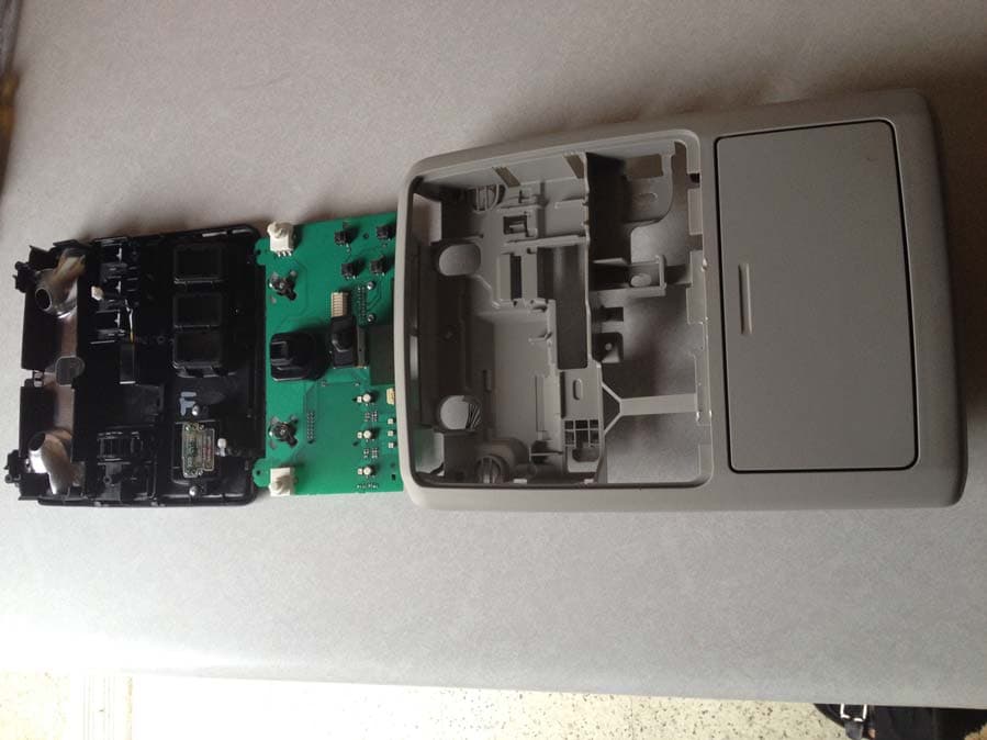
CB2775AHL5
Apr 29, 2013Universal Garage Door Opener w/ FHSS TX
Equipment Class
DSR - Part 15 Remote Control/Security Device Transceiver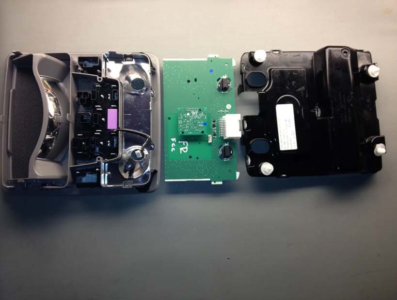
CB2440AHL5
Feb 24, 2013Universal Garage Door TX w/ FHSS TX
Equipment Class
DSS - Part 15 Spread Spectrum Transmitter