CB2VWHL3Universal Garage Door Opener
Johnson Controls Interiors L.L.C.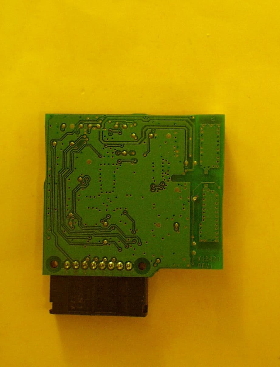
Click to zoom
Application Details
- Equipment Class
- DSC - Part 15 Security/Remote Control Transmitter
- Date of Grant
- Feb 13, 2001
- Application Purpose
- Original Equipment
- Date of Application
- Dec 26, 2000
- Equipment Note
- Universal Garage Door Opener
- Frequency Range
- 411.00000000 - 420.00000000
- Country
- United States
Documents & Files


Document Text
Text extracted from the exhibit documents filed with the FCC. Open a document above to read the original.
Users Manual
Test report #20000373FFCC 15.231 for CB2VWHL3FCC ID: CB2VWHL3 Tested November 18, 2000 AHD EMC Lab, 92723 M152, Dowagiac, MI 49047, (616) 424-7014130624 Exhibit N: Page 1 of 4 EXHIBIT N: U SER ’ S M ANUAL The proposed Owners Manual for the Homelink® series Universal Garage Door Opener is reproduced here. HomeLink ® Universal Transceiver Suggested Owner’s Manual Text October, 1999 HomeLink ® Universal Transceiver The HomeLink ® Universal Transceiver in your vehicle provides a convenient way to replace up to three hand- held transmitters with a single built-in component. This innovative feature will learn the radio frequency codes of most current transmitters used to activate devices such as garage doors, entry door locks, estate gates, security systems, and home or office lighting. For additional information on HomeLink and/or HomeLink compatible products, call 1-800-355-3515 or refer to the HomeLink web site at www.home link.jci.com . Precautions When programming the HomeLink Universal Transceiver to a garage door opener or entry gate, make sure that people and objects are out of the way to prevent potential harm or damage. Do not use the HomeLink Universal Transceiver with any garage door opener that lacks the safety stop and reverse feature as required by federal safety standards. (This includes any garage door opener model manufactured before April 1, 1982.) A garage door opener which cannot detect an object, signaling the door to stop and reverse, does not meet current federal safety standards. Using a garage door opener without these features increases risk of serious injury or death. For more information, call 1-800-355-3515 or on the internet at www.homelink.jci.com. Retain the original transmitter for future programming procedures (i.e., new vehicle purchase). It is also suggested that upon the sale of the vehicle, the programmed HomeLink Universal Transceiver buttons be erased for security purposes (follow step 1 in the “Programming” portion of this text). Test report #20000373FFCC 15.231 for CB2VWHL3FCC ID: CB2VWHL3 Tested November 18, 2000 AHD EMC Lab, 92723 M152, Dowagiac, MI 49047, (616) 424-7014130624 Exhibit N: Page 2 of 4 Programming Note : For best results, replace the battery in the hand-held transmitter with a new battery before programming. If your garage door opener receiver (located in the garage) is equipped with an antenna, make sure the antenna is completely uncoiled and hangs straight down. 1. Press and hold the two outside buttons - releasing only when the indicator light begins to flash after 20 seconds . (This procedure erases the factory set default codes and does not have to be followed to program additional hand-held transmitters.) 2. Hold the end of the hand-held transmitter of the device you wish to train approximately one to three inches away from the HomeLink surface - keeping the indicator light in view. (For placement questions, please contact HomeLink at 1-800-355-3515 or on the internet at www.home link.jci.com. ) 3. Using both hands, simultaneously push the hand-held transmitter button and the desired HomeLink button. Do not re le ase the buttons until ste p 4 has be e n comple te d. Note: Some entry gates and garage door openers may require you to replace this programming step (#3) with the procedures noted in the “Canadian Programming / Gate Programming” section. 4. The HomeLink indicator light will flash, first slowly and then rapidly. When the indicator light flashes rapidly, release both buttons. (The rapid flashing light indicates successful programming of the new frequency signal.) If, after 20 seconds, the indicator light does not flash rapidly, release both the HomeLink and the hand-held transmitter buttons and repeat steps tw o through four. However, position the hand-held transmitter at a different length and/or angle until the indicator light begins to flash rapidly. Release both buttons after the indicator light flashes rapidly. Refer to “Rolling Code Programming” and/or “Canadian Programming/Gate Programming” for additional procedures if necessary. To activate the garage door or other programmed device upon successfully completing the steps above, press and hold the HomeLink button - releasing when the device begins to activate. To program the remaining tw o buttons, follow steps 2 through 4. If you do not successfully program the HomeLink Universal Transceiver to learn the signal of the hand-held transmitter, refer to “Rolling Code Programming” within this text or call toll-free for customer assistance at 1-800- 355-3515 or on the internet at www.home link.jci.com. Test report #20000373FFCC 15.231 for CB2VWHL3FCC ID: CB2VWHL3 Tested November 18, 2000 AHD EMC Lab, 92723 M152, Dowagiac, MI 49047, (616) 424-7014130624 Exhibit N: Page 3 of 4 Canadian Programming / Gate Programming Canadian frequency law s, and the technology of some entry gates, require you to “cycle” (press and re-press the hand- held transmitter button every tw o seconds) during programming. Continue to press and hold the desired HomeLink button (note steps 3 through 5 in the “Programming” portion of this text) w hile you “cycle” your hand-held transmitter until the frequency signal has been learned. The indicator light w ill flash slowly and then rapidly upon successful training. Note: When programming a garage door opener or gate, it is advised to unplug the device during the “cycling” process to prevent possible motor burn-up Operating the HomeLink ® Universal Transceiver To operate, simply press the programmed HomeLink button. Activation will now occur for the trained product (garage door, security system, entry door lock, estate gate, or home or office lighting). For convenience, the hand-held transmitter of the device may also be used at any time. Rolling Code Programming Rolling code garage door openers (or other rolling code devices) which are “code protected” and manufactured after 1996, may be determined by the following: A.Reference the garage door opener o…
Text truncated - open the document above for the full version.
Attestation Statements
Test report #20000373FFCC 15.231 for CB2VWHL3FCC ID: CB2VWHL3 Tested November 18, 2000 AHD EMC Lab, 92723 M152, Dowagiac, MI 49047, (616) 424-7014130623 Exhibit M: Page 1 of 1 EXHIBIT M: RF E XPOSURE I NFORMATION [2.1093( C )] The manufacturer and applicant: JOHNSON CONTROLS INTERIORS, LLC. One Prince Center Holland, Michigan 49423 Product: Homelink® Universal Garage Door Opener Model: CB2VWHL3 Applicable Rules: 47CFR Part 15.231 Pursuant to 47CFR Part 1.1307(b), 47CFR Part 2.1091(c), and 47CFR Part 2.1093(c) this transmitting device, compliant to 47CFR Part 15.231, is categorically excluded from evaluation regarding the Maximum Permissible Exposure of RF energy.
Cover Letter(s)
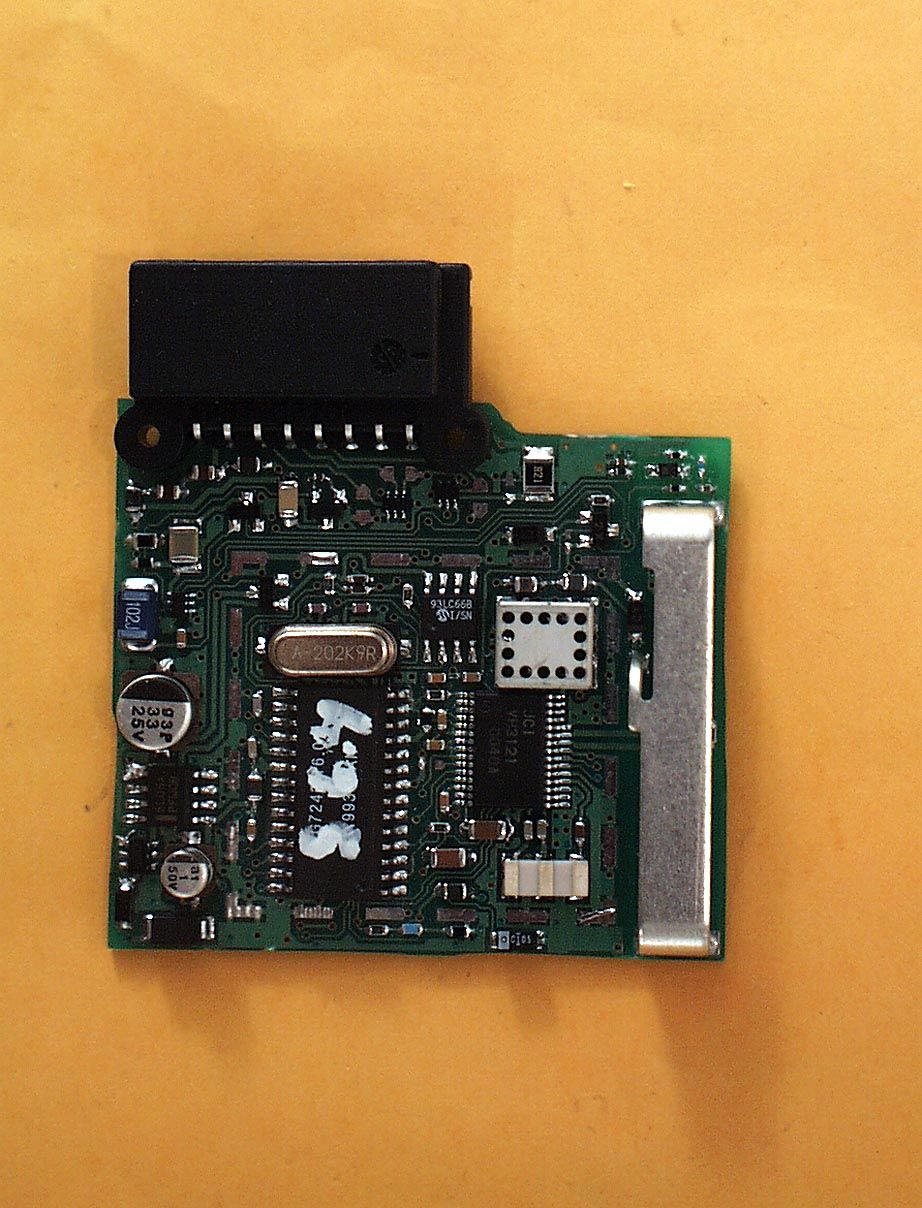
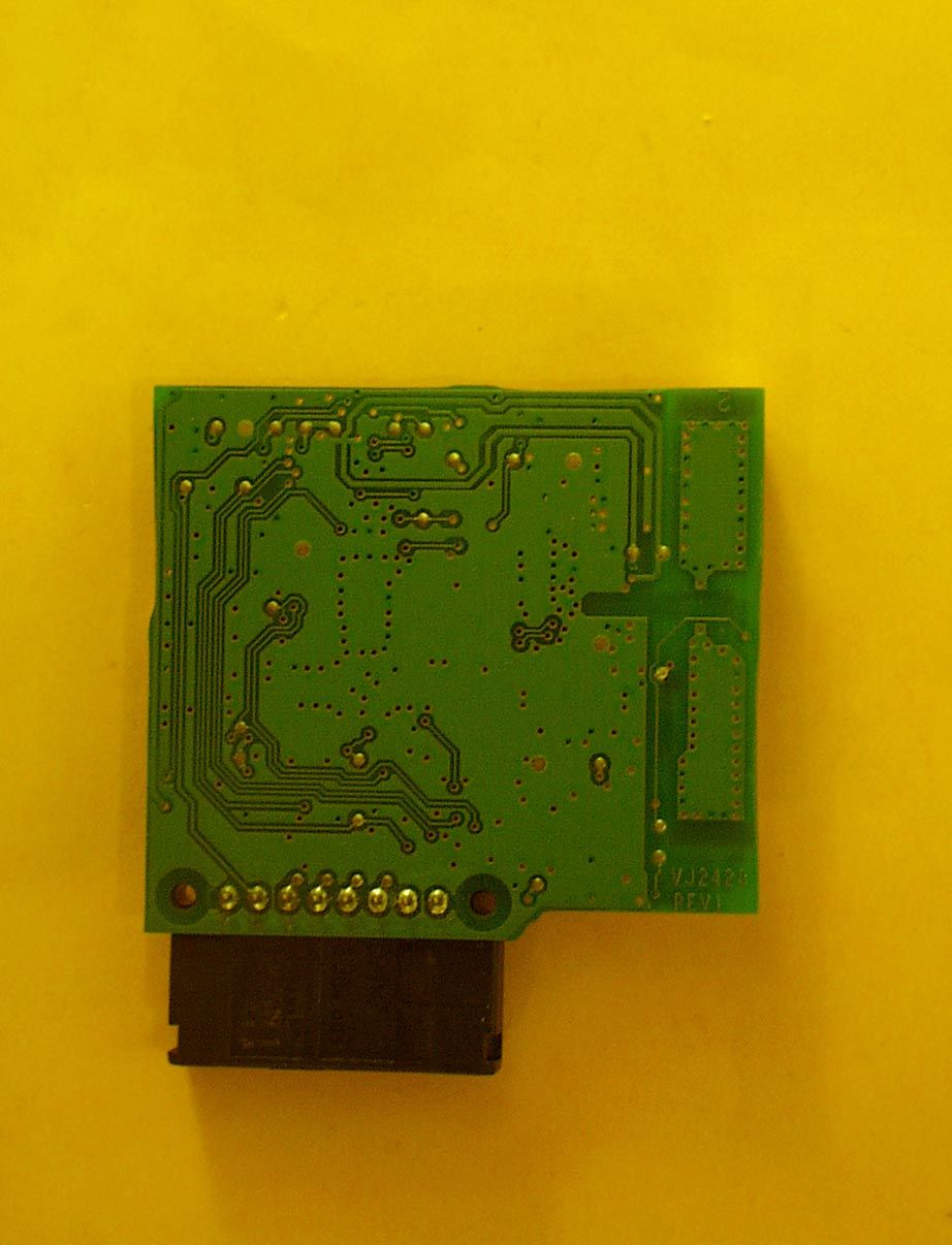
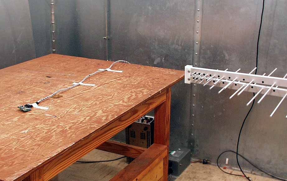
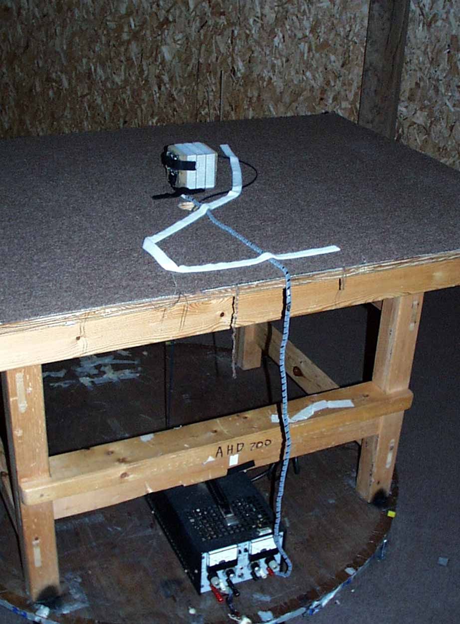
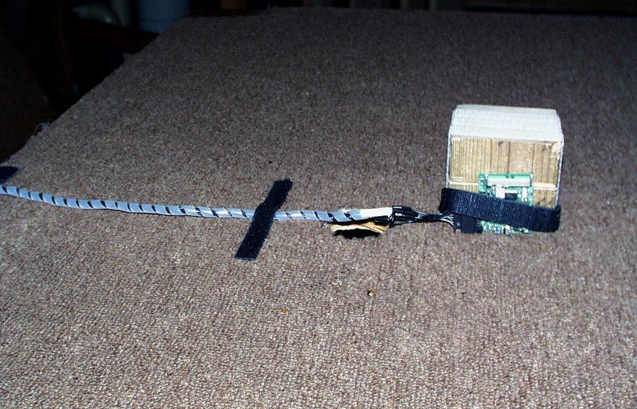
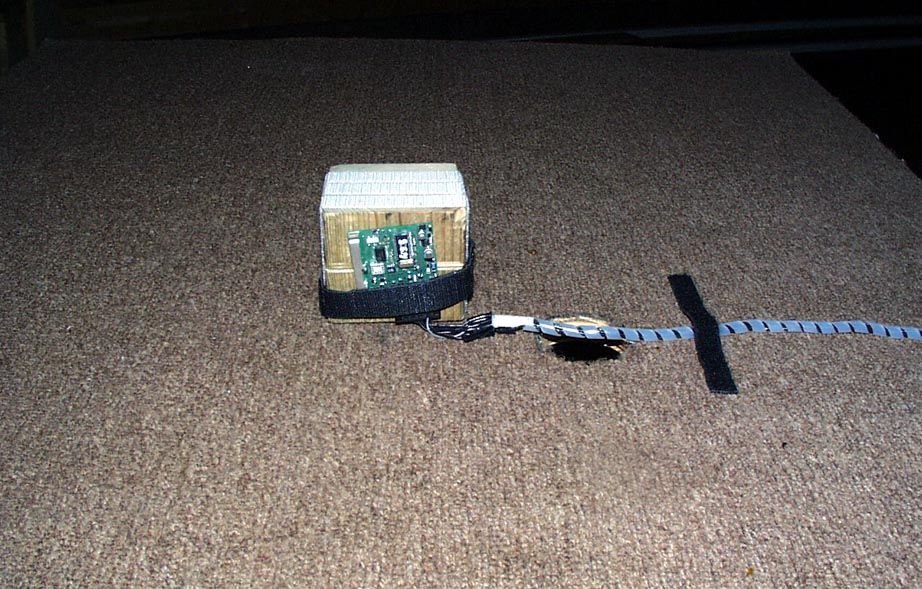
AHD EMC Lab, 92723 M152, Dowagiac, MI 49047, (616) 424-7014130590 Exhibit A: Page 1 of 2 NVLAP ACCREDITED NARTE Certified Engineer Professional Engineer Federal communications CommissionDecember 8, 2000 Equipment Approval Services, P.O. Box 358315 Pittsburgh, PA 15251-5315 Attention: Authorization & Evaluation Division Re: Application for Certification of Johnson Controls Transmitter under 47CFR 15.231. FCC ID: CB2VWHL3 Gentlemen: On behalf of the applicant, Johnson Controls Interiors, LLC, please find attached the submittal materials for certification of the JCI Universal Garage Door Opener, Model CB2VWHL3 This generation of their Homelink® series is capable of learning the current garage door transmit frequencies from 288MHz through 420MHz with pulse modulation, using duty cycles from 30 through 80 percent. Pursuant to 47CRF 0.459, Johnson Controls Interiors requests that these listed exhibits be held confidential. Exhibit GTheory/Description of Operation, Exhibit H:Circuit Block Diagrams Exhibit I:Schematics Exhibit J:Bill of Material, Parts List Johnson Controls Interiors has invested considerable resources into developing this Homelink® series. Having the listed exhibits available to ‘competition’ would negate the advantage achieved in developing this product. Since their Homelink® series transmitters will be a major product line for Johnson Controls Interiors, not protecting the details of the design will result in a financial hardship for the company. The complete List of the Exhibits in this submittal package appears on Page 2 of this cover letter. Your prompt consideration of this application for product certification will be greatly appreciated. Should you have any questions regarding the content of this report, kindly contact me. Sincerely, Ted Chaffee, Technical Lab Manager Narte Certified Engineer, #EMC-002025-NE tel/fax: 616. 424.7014 email: [email protected], or [email protected] Test report #20000373FFCC 15.231 for CB2VWHL3FCC ID: CB2VWHL3 Tested November 18, 2000 AHD EMC Lab, 92723 M152, Dowagiac, MI 49047, (616) 424-7014130590 Exhibit A: Page 2 of 2 Table of Contents Form 731, form 159 with payment EXHIBIT A: Cover Letter / Table of ContentsTotal Pages 2 EXHIBIT B: Statements of Attestation [2.911(d)]Total Pages 3 Attesting to Accuracy of DataExhibit B, File “EXB_p1DataAttst.jpg” Public Notice 22504 Exhibit B, File “EXB_p1DataAttst.jpg” Power of Attorney Exhibit B, File “EXB_p2PowrOAttrny.jpg” AHD AccreditationExhibit B, File “EXB_p3NVLAPCert.jpg” EXHIBIT C: Description of Product [2.1033(b6)] Total Pages 1 EXHIBIT E: Product photos - Printed Circuit Board [2.1033(b7)] Two photosTotal Pages 2 EXHIBIT F: ID Label / Location [2.925,2.926,2.1033(b2,7),15.19(a3)] Total Pages 3 EXHIBIT G: Description of Operation [2.1033(b4)] Total Pages 1 EXHIBIT H: Circuit Block Diagram [2.1033(b5)] Total Pages 1 EXHIBIT I:Schematics [2.1033(b5)] Total Pages 1 Exhibit I, File “EXI_TXSchem.pdfExhibit I, File “EXI_INSchem.pdf EXHIBIT J: Parts List/Tune-up Information [2.1033(b5] Total Pages 2 Exhibit J, File “EXJ_TXParts.pdf”Exhibit J, File “EXJ_INParts.pdf” EXHIBIT K: Report of Measurements [2.1033(b6)] Total Pages 33 Detailed Table of ContentsExhibit K, Part 1 of 2, Page 2 and Part 2 of 2, Page 1 Manufacturer/Applicant [2.1033(b1)Exhibit K, Part 1 of 2, Page 4 Measurement/Test Facility & EquipmentExhibit K, Part 1 of 2, Page 4 Configuration/Setup [2.1033(b8)]Exhibit K, Part 1 of 2, Page 5 Test Standards / Methods Used [2.1033(b6)] Exhibit K, Part 1 of 2, Page 6 Test Methodology [2.1033(b6)Exhibit K, Part 1 of 2, Page 6 Test Data [2.1033(b6)Exhibit K, Part 2 of 2 Summary of ResultsExhibit K, Part 2 of 2, Page 2 Level vs Supply Voltage [15.31(e)]Exhibit K, Part 2 of 2, Page 5 Occupied BandwidthExhibit K, Part 2 of 2, Page 6 Radiated Field Strength [15.231(b)] Exhibit K, Part 2 of 2, Page 8 EXHIBIT L: Setup photos [2.1033(b8)] Five photosTotal Pages 3 EXHIBIT M: RF Exposure Information [2.1093(c)]Total Pages 1 EXHIBIT N: User’s Manual Total Pages 4
ID Label/Location Info
Test report #20000373FFCC 15.231 for CB2VWHL3FCC ID: CB2VWHL3 Tested November 18, 2000 AHD EMC Lab, 92723 M152, Dowagiac, MI 49047, (616) 424-7014130597 Exhibit F: Page 1 of 2 EXHIBIT F: E QUIPMENT L ABEL [2.925, 2.926, 2.1033( B 2,7), 15.19( A 3)] LABEL EXAMPLE Refer to picture file “EXF_Label.pdf” The FCC Identifier assigned to the EUT is FCC ID: CB2VWHL3. This number will be imprinted on the 1.0”x1.5” high temperature polyester matte white label. The label will be placed on the exterior of the CB2VWHL3 housing using an acrylic adhesive that will permanently affix the label. LABEL LOCATION EXAMPLE Refer to Location #10 in file “EXF_LabelLoc.pdf” Because of the small size of the device and because the installation is inside a portion of the automobile, the following statements will appear in the user’s manual. Refer to Exhibit N for the entire text of the user’s manual. “This device complies with Part 15 of the FCC rules and with RSS-210 of the Industry Canada. Operation is subject to the following two conditions: (1) This device may not cause harmful interference, and (2) This device must accept any interference that may be received including interference that may cause undesired operation. WARNING: The transmitter has been tested and complies with FCC and Industry Canada rules. Changes or modifications not expressly approved by the party responsible for compliance could void the user’s authority to operate the device.”
Parts List/Tune Up Info
Test report #20000373FFCC 15.231 for CB2VWHL3FCC ID: CB2VWHL3 Tested November 18, 2000 AHD EMC Lab, 92723 M152, Dowagiac, MI 49047, (616) 424-7014130603 Exhibit J: Page 1 of 2 EXHIBIT J: P ART S L IST / T UNING I NFORMATION [2.1033( B 5)] The Parts List and Component Placement Diagram portion of this Exhibit J is located in two “pdf” files. The transmit PCB information is in the “pdf” file entitled “EXJ_TXParts.pdf”. Tuning: (Programming) The user programs the CB2VWHL3 as outlined in the Users Manual, Exhibit N. A summary is provided here. 1. Pressing the two outside buttons until the indicator LED begins to flash resets the memory. 2. Holding the hand-held transmitter to be copied near the CB2VWHL3 and simultaneously activating the hand-held transmitter and one of the user buttons until the indicator LED flashed rapidly trains the unit to duplicate the hand-held transmitter. The information is stored in the non-volatile memory of the CB2VWHL3. During usage, when the “trained” button is pressed, the CB2VWHL3 recalls the stored information. 1. The Voltage Controlled Oscillator (VCO) is set on the desired RF carrier frequency. 2. The antenna is coarse tuned by sweeping twice around the expected tuning point. 3. The antenna is fine tuned with 9 pulses of approximately 210 uS with 11 mS off. 4. The VCO is then modulated with the appropriate garage door opener bit code from the non- volatile memory.
Test Report
Test report #20000373FFCC 15.231 for CB2VWHL3FCC ID: CB2VWHL3 Tested November 18, 2000 AHD EMC Lab, 92723 M152, Dowagiac, MI 49047, (616) 424-7014130594 Exhibit C: Page 1 of 1 EXHIBIT C: D ESCRIPTION OF P RODUCT [2.1033(b6)] The Johnson Controls Interiors Homelink® CB2VWHL3 Universal Garage Door Opener is a low-power transceiver OEM device that is installed into an overhead console of the automobile. The installation is provided by trained technicians during the course of the manufacturer of the automobile. It is powered by the 12volt system of the automobile. This Universal Garage Door Opener has the capability to: 1. Learn the frequency and bit code format of the user’s existing garage door remote control devices and 2. Reproduce and transmit the frequency and bit code format to remotely operate the user’s garage door. The unit is designed for the periodic operation of a control signal which activates typically a garage door. The unit is supplied to the automobile manufacturer without harness nor user interface. The user interface will consist of a PCB with three control buttons and an LED. For testing purposes a typical button assembly and 8-conductor cable harness were used to interface to the unit The unit is only operational when the user depresses one of the three control buttons. The unit becomes inactive after release of the control button. This three-button Homelink® unit replaces up to three hand-held transmitters. In addition to the typical operation of the garage door, the unit will learn the radio frequency codes of other transmitter types to activate entry door locks, estate gates, security systems, and home or office lighting. The antenna system is an integral part of the unit. It cannot be altered nor replaced by the user. Service of this system is only available from the Automobile Manufacturer’s Dealerships and Johnson Controls Interiors, LLC.
Test Report
A H D EMC Laboratory 92723 M-152, Dowagiac, MI 49047 USA Phone: (616) 424-7014 www.ahde.com AHD EMC Lab, 92723 M152, Dowagiac, MI 49047, (616) 424-7014130637 Exhibit K: Page 1 of 8 EXHIBIT K P ART 1 OF 2: R EPORT OF M EASUREMENTS [2.1033( B 6)] Test Report for FCC ID: CB2VWHL3 FCC Part 2.1031, Part 15 Subpart C(15.231) Report #20000373F Issued 12/08/00 T RANSMITTER M ODEL CB2VWHL3 OF H OMELINK ® III SERIES Prepared for:Mr. David Blaker Johnson Controls Interiors, LLC One Prince Center Holland, MI 49423 Test Date(s): November 13,14,17,18, 2000 data recorded bywitnessed by Ted Chaffee, NCECraig Harder Test Engineer, AHD This report prepared by: Ted Chaffee, NCE Technical Manager/Test Engineer, AHD Test report #20000373FFCC 15.231 for CB2VWHL3FCC ID: CB2VWHL3 Tested November 18, 2000 AHD EMC Lab, 92723 M152, Dowagiac, MI 49047, (616) 424-7014130637 Exhibit K: Page 2 of 8 TABLE OF CONTENTS EXHIBIT K Part 1 of 2: Report of Measurements [2.1033(b6)]............................................................. 1 TABLE OF CONTENTS ...............................................................................................................2 Statements Concerning this Report............................................................................................... 3 Manufacturer/Applicant [2.1033(b1)]............................................................................................ 4 Measurement/Test Site Facility & Equipment................................................................................. 4 Test Site [2.948, 2.1033(b6)]............................................................................................. 4 Measurement Equipment Used [2.947(d), 15.31(b)]............................................................... 4 Tested Configuration /Setup: [2.1033(b8)]..................................................................................... 5 Support Equipment & Cabling................................................................................................ 5 Setup Diagram..................................................................................................................... 5 Standards Applied to Test: [2.1033(b6)]....................................................................................... 6 Test Methodology: [2.1033(b6)]................................................................................................... 6 Test report #20000373FFCC 15.231 for CB2VWHL3FCC ID: CB2VWHL3 Tested November 18, 2000 AHD EMC Lab, 92723 M152, Dowagiac, MI 49047, (616) 424-7014130637 Exhibit K: Page 3 of 8 Statements Concerning this Report Test Traceability: The calibration of all measuring and test equipment and the measured data using this equipment are traceable to the National Institute for Standards and Technology (NIST). Limitations on results: The test results contained in this report relate only to the Item(s) tested. Any electrical or mechanical modification made to the test item subsequent to the test date shall invalidate the data presented in this report. Any electrical or mechanical modification made to the test item subsequent to this test date shall require an evaluation to verify continued compliance. Limitations on copying: This report shall not be reproduced, except in full, without the written approval of AHD. Limitations of the report: This report shall not be used to claim product endorsement by NVLAP, FCC, or any agency of the US Government. Statement of Test Results Uncertainty: Following the guidelines of NAMAS publication NIS81 and NIST Technical Note 1297, the Measurement Uncertainty at a 95% confidence level is determined to be: ± 3.6 dB Test report #20000373FFCC 15.231 for CB2VWHL3FCC ID: CB2VWHL3 Tested November 18, 2000 AHD EMC Lab, 92723 M152, Dowagiac, MI 49047, (616) 424-7014130637 Exhibit K: Page 4 of 8 Manufacturer/Applicant [2.1033(b1)] The manufacturer and applicant: JOHNSON CONTROLS INTERIORS, LLC. One Prince Center Holland, Michigan 49423 Measurement/Test Site Facility & Equipment Test Site [2.948, 2.1033(b6)] The AHD test facility is centered on 9 acres of rural property near Sister Lakes, Michigan. The mailing address is 92723 M-152, Dowagiac, Michigan 49047. This test facility is NVLAP accredited (LabCode 200129-0). It has been fully described in a report filed with the FCC and Industry Canada. The report filed with the FCC is, dated November 5, 1996, was accepted by the FCC in a letter dated January 15, 1997 and reconfirmed July 14, 2000, (31040/SIT 1300F2). The report filed with Industry Canada, dated August 11, 1998, was accepted via a letter dated September 1, 1998, (file:IC3161). Measurement Equipment Used [2.947(d), 15.31(b)] EquipmentModelS/NLast CalCalibration Date Interval HP EMI Receiver systemHP 8546A RF Filter SectionHP-85460A3448A0028324-Aug-0012 month RF Receiver SectionHP-85462A3625A0034224-Aug-0012 month EMCO BiconiLog Antenna3142107728-Jul-0012 months (3-M) Type 129FF Ultra Flex LowLossRG58/U9910-1227-Jun-00 6 months 50ohm CoaxRG223/U980230227-Jun-0012 months University of Mich Double Ridge Horn0.2 - 5.0GHzC16-Mar-9924 months 6 ft. Andrew DF4 Heliax9912-0213-Dec-9912 months Measurement Environment The tests were performed with the equipment under test, and measurement equipment inside the all-weather enclosure. Ambient temperature was 22deg.C., the relative humidity 40%. Test report #20000373FFCC 15.231 for CB2VWHL3FCC ID: CB2VWHL3 Tested November 18, 2000 AHD EMC Lab, 92723 M152, Dowagiac, MI 49047, (616) 424-7014130637 Exhibit K: Page 5 of 8 Tested Configuration /Setup: [2.1033(b8)] Support Equipment & Cabling Setup Diagram Legend DescriptionModelSerial No. / Part No.EMC Consideration A[EUT] Universal Garage Door Opener [JCI] CB2VWHL3 --FCC ID: CB2VWHL3 B12V DC Power Supply [Trygon] DL40-1 7968152Located on the turntable base below the EUT table. 1Power Supply Cable Harness ----1.5 meters, Unshielded, 8-lead lightly twisted cable harness. Setup Diagram Note: Setup photographs ar…
Text truncated - open the document above for the full version.
Test Report
Test report #20000373FFCC 15.231 for CB2VWHL3FCC ID: CB2VWHL3 Tested November 18, 2000 AHD EMC Lab, 92723 M152, Dowagiac, MI 49047, (616) 424-7014130638 Exhibit K: Page 1 of 25 EXHIBIT K P ART 2 OF 2: R EPORT OF M EASUREMENTS [2.1033( B 6)]. TABLE OF CONTENTS EXHIBIT K Part 2 of 2: Report of Measurements [2.1033(b6)].............................................................. 1 TABLE OF CONTENTS ...............................................................................................................1 Summary of Results: ................................................................................................................... 2 Changes made to achieve compliance................................................................................... 3 Test Data [2.1033(b6)]................................................................................................................ 3 Modulation Characteristics.................................................................................................... 3 Relative Emission Level vs. Supply Voltage [15.31(e)]............................................................. 5 Occupied Bandwidth [15.231(c)]........................................................................................... 6 Restricted Bands: [15.205]................................................................................................... 7 Radiated Field Strength Measurements: [15.231(b), 15.205] .................................................. 8 Radiated Field Strength Measurements ................................................................................10 Field Strength Measurements of Fundamental : [15.231(b)]............................................11 Field Strength Measurements of Harmonics: [15.231(b), 15.205]....................................12 Calculation of Field Strength of Tuning Pulses: [15.231(b)], 15.31(c)]...............................15 APPENDIX: Tune Pulses - Data Details..................................................................................20 Test report #20000373FFCC 15.231 for CB2VWHL3FCC ID: CB2VWHL3 Tested November 18, 2000 AHD EMC Lab, 92723 M152, Dowagiac, MI 49047, (616) 424-7014130638 Exhibit K: Page 2 of 25 Summary of Results: 1.This test series evaluated the Equipment Under Test to FCC Part 15, SubPart C. 2.The system tested is compliant to the requirement of CFR 47, FCC Part 15, SubPart C for periodic operation in the allowed frequency bands above 70MHz, ( Part 15.231 ). 3.The equipment under test was received on November 13, 2000 and this test series commenced on November 13, 2000. 4.The line conducted emission testing does not apply to this product. The device is powered from a 12 volt automobile source. 5.The preliminary scan for spurious emissions conducted in a shielded room indicated low level spurious signals. 6.The frequencies selected for final evaluation include 288MHz, 310MHz, and 418MHz. This is in accordance with 47 CFR 15.31(m). The 310MHz was selected as a mid-range frequency because it is the predominant frequency used in controlling garage doors. Past correspondence with the FCC regarding the selection of frequencies and test setup suggest this judgment as appropriate. 7.Occupied Band Width of the transmitted signal, at the 20dB point, nearest the limit was measured to be 563KHz. This measurement occurred with the EUT transmitting at 288MHz with a pulse modulation of 30% duty cycle. This measurement is within the allowed 720KHz bandwidth. The greatest bandwidth measured was 585KHz with the EUT transmitting at 418MHz 8.The field strength level of the fundamental was measured for 288MHz, 310MHz, and 418MHz. The evaluation showed the emission nearest the limit occurred while operating at 310MHz with 500Hz pulsed modulation at a 50% duty cycle. The EUT was positioned on the ‘side’ and the receive antenna oriented in the horizontal polarization. This signal was measured to be 0.6dB below the limit of 75.3dBuV/m (5821uV/m). 9.The evaluation of the field strength levels of the harmonics showed the emission nearest the limit occurred while operating at 288MHz with 500Hz pulsed modulation at 30% duty cycle. The EUT was positioned on the ‘flat’; and the receive antenna oriented in the horizontal polarization. This signal, at 576MHz, was measured to be 1.7dB below the limit of 53.8dBuV/m (490uV/m). 10.The digital spurious emissions, nearest the limit, occurred at 60MHz. The quasi-peak level was measured to be 24.2dBuV/m which is 15.8dB below the FCC Class B limit. 11.The average value of the coarse tune pulses over a 100mSec time, nearest the limit, occurred at 418MHz. The average measurement was determined to be 5380uV/m which is 5.7dB below the limit of 10,333uV/m.. 12. The average value of the fine tune pulses over a 100mSec time, nearest the limit, occurred at 418MHz. The average measurement was determined to be 1956uV/m which is 14.5dB below the limit of 10,333uV/m. Test report #20000373FFCC 15.231 for CB2VWHL3FCC ID: CB2VWHL3 Tested November 18, 2000 AHD EMC Lab, 92723 M152, Dowagiac, MI 49047, (616) 424-7014130638 Exhibit K: Page 3 of 25 Changes made to achieve compliance 1. NONE Test Data [2.1033(b6)] Modulation Characteristics Typical encoding at 310MHz: Consisting of pulses of differing duty cycles. 310MHz, 500Hz Modulation, 30% duty cycle Test report #20000373FFCC 15.231 for CB2VWHL3FCC ID: CB2VWHL3 Tested November 18, 2000 AHD EMC Lab, 92723 M152, Dowagiac, MI 49047, (616) 424-7014130638 Exhibit K: Page 4 of 25 310MHz, 500Hz Modulation, 50% duty cycle 310MHz, 500Hz Modulation, 80% duty cycle Test report #20000373FFCC 15.231 for CB2VWHL3FCC ID: CB2VWHL3 Tested November 18, 2000 AHD EMC Lab, 92723 M152, Dowagiac, MI 49047, (616) 424-7014130638 Exhibit K: Page 5 of 25 Relative Emission Level vs. Supply Voltage [15.31(e)] The relative emission level as the supply voltage varied is presented in the charts below. TX OUTPUT vs. Voltage LEVEL DUT= CB2VWHL3, 310MHz, 80%duty cycle …
Text truncated - open the document above for the full version.
Test Report
FCC ID: CB2VWHL3 Confirmation No. EA99627 Correspondence Ref. No. 18037 RE: Calculation of FCC limits Part 15.231 The limits provided for in CFR47 Part 15.231(b) indicate that - For the frequency range 260MHz - 470MHz, the limit is a linear interpolation between 3750uV/m and 12500uV/m where the limit at 260MHz is 3750uV/m and the limit at 470MHz is 12500uV/m. A formula to calculate the limit is established w ith a ratio linearly equating the frequency range to the limit range. ( F 0 - F L ) / ( F H - F L ) = ( L 0 - L L ) / ( L H - L L ) where F 0 and L 0 represent the frequency in question and its limit where F L and L L represent the lower frequency ( 260MHz ) and its limit ( 3750uV/m ). Where F H and L H represent the higher frequency ( 470MHz ) and its limit ( 12500uV/m ). The calculations for the frequencies included in the application are: 288MHz( 288 - 260 ) / ( 470 - 260 ) = (L 0 - 3750 ) / ( 12500 - 3750 ) ( 28 / 210 ) * ( 8750 ) = L 0 - 3750 L 0 = 1166.7 + 3750 L 0 = 4916.7 uV/m 310MHz( 310 - 260 ) / ( 470 - 260 ) = (L 0 - 3750 ) / ( 12500 - 3750 ) ( 50 / 210 ) * ( 8750 ) = L 0 - 3750 L 0 = 2083.3 + 3750 L 0 = 5833.3 uV/m 418MHz( 418 - 260 ) / ( 470 - 260 ) = (L 0 - 3750 ) / ( 12500 - 3750 ) ( 158 / 210 ) * ( 8750 ) = L 0 - 3750 L 0 = 6583.3 + 3750 L 0 = 10333.3 uV/m The limit in dB terms is calculated as the result of 20 times the log of the uV/m limit. 288MHzdB limit is 20 * LOG( 4916.7 uV/m) = 73.8 dBuV/m 310MHzdB limit is 20 * LOG( 5833.3 uV/m) = 75.3 dBuV/m 418MHzdB limit is 20 * LOG( 10333.3 uV/m) = 80.3 dBuV/m
Contact Information
Applicant
Rick Markiewicz(Electronics Engineering Manager)
Technical Contact
Johnson Controls InteriorsDavid A Blaker
[email protected]616 394-8013
92723 M-152 · Holland, Michigan · United States
Non-Technical Contact
AHDTed Chaffee
[email protected]616 424-7014
Test Firm
AHD EMC LaboratoryGordon Helm
Technical Specifications
| # | Rule Parts | Frequency Range | Power Output |
|---|---|---|---|
| 4 | 15C | 411 MHz - 420 MHz | - |
Other Applications from Johnson Controls Interiors L.L.C.

CB2-BLUE15M-TCU
Mar 20, 2014Automotive Telematics Module with Handsfree Bluetooth
Equipment Class
DSS - Part 15 Spread Spectrum Transmitter
CB2-BLUE15M
Jan 19, 2014Bluetooth Telematics Device
Equipment Class
DSS - Part 15 Spread Spectrum Transmitter
CB262932
Jul 15, 2013Automotive Electronics Infotainment Head Unit with Bluetooth and WLAN
Equipment Class
DTS - Digital Transmission System
CB2775AHL5
Apr 29, 2013Universal Garage Door Opener w/ FHSS TX
Equipment Class
DSR - Part 15 Remote Control/Security Device Transceiver
CB2440AHL5
Feb 24, 2013Universal Garage Door TX w/ FHSS TX
Equipment Class
DSS - Part 15 Spread Spectrum Transmitter