CB2W220HL3Universal Garage Door Opener
Johnson Controls Interiors L.L.C.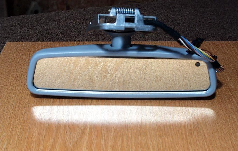
Click to zoom
Application Details
- Equipment Class
- DSC - Part 15 Security/Remote Control Transmitter
- Date of Grant
- May 23, 2002
- Application Purpose
- Original Equipment
- Date of Application
- May 23, 2002
- Equipment Note
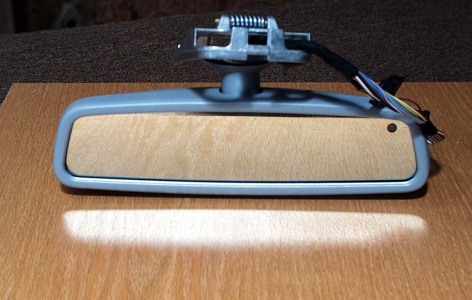
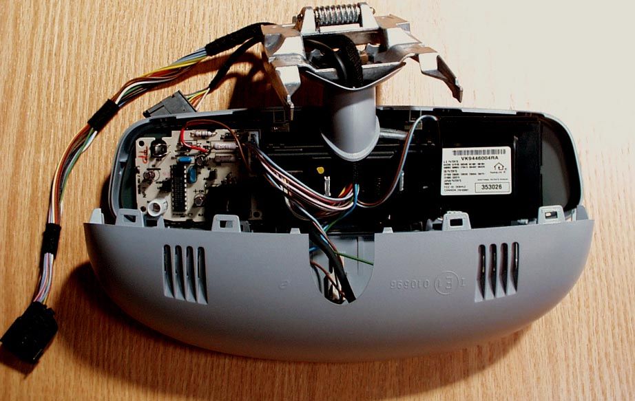
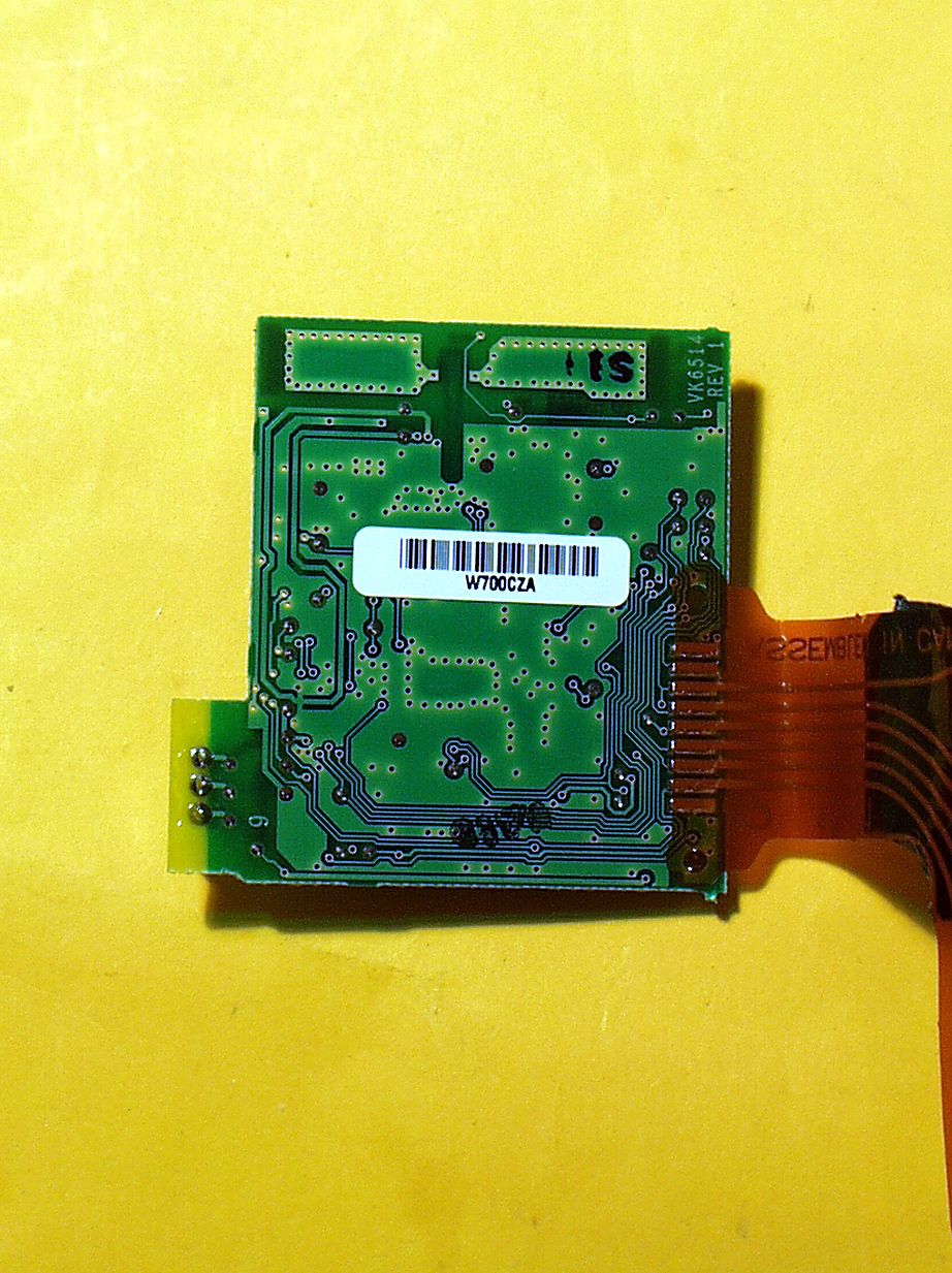
- Universal Garage Door Opener
- Frequency Range
- 411.00000000 - 420.00000000
- Country
- United States
Documents & Files
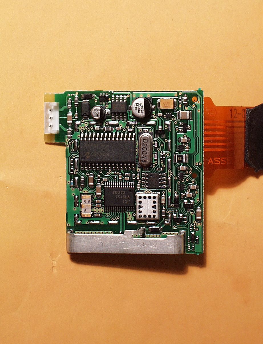
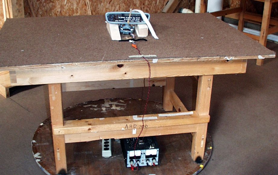
Document Text
Text extracted from the exhibit documents filed with the FCC. Open a document above to read the original.
Users Manual
The Owners Manual for the Homelink® series Universal Garage Door Opener is reproduced here. HomeLink ® Universal Transceiver Suggested Owner’s Manual Text March 2002 HomeLink ® Universal Transceiver The HomeLink ® Universal Transceiver in your vehicle provides a convenient way to replace up to three hand- held transmitters with a single built-in component. This innovative feature will learn the radio frequency codes of most current transmitters used to activate devices such as garage doors, entry door locks, estate gates, security systems, and home or office lighting. For additional information on HomeLink and/or HomeLink compatible products, call 1-800-355-3515 or refer to the HomeLink web site at www.home link.jci.com . Precautions When programming the HomeLink Universal Transceiver to a garage door opener or entry gate, make sure that people and objects are out of the way to prevent potential harm or damage. Do not use the HomeLink Universal Transceiver with any garage door opener that lacks the safety stop and reverse feature as required by federal safety standards. (This includes any garage door opener model manufactured before April 1, 1982.) A garage door opener which cannot detect an object, signaling the door to stop and reverse, does not meet current federal safety standards. Using a garage door opener without these features increases risk of serious injury or death. For more information, call 1-800-355-3515 or on the internet at www.homelink.jci.com. Retain the original transmitter for future programming procedures (i.e., new vehicle purchase). It is also suggested that upon the sale of the vehicle, the programmed HomeLink Universal Transceiver buttons be erased for security purposes (follow step 1 in the “Programming” portion of this text). Programming Note : For best results, replace the battery in the hand-held transmitter with a new battery before programming. If your garage door opener receiver (located in the garage) is equipped with an antenna, make sure the antenna is completely uncoiled and hangs straight down. 1. Press and hold the two outside buttons - releasing only when the indicator light begins to flash after 20 seconds . (This procedure erases the factory set default codes and does not have to be followed to program additional hand-held transmitters.) 2. Hold the end of the hand-held transmitter of the device you wish to train approximately one to three inches away from the HomeLink surface - keeping the indicator light in view. (For placement questions, please contact HomeLink at 1-800-355-3515 or on the internet at www.home link.jci.com. ) 3. Using both hands, simultaneously push the hand-held transmitter button and the desired HomeLink button. Do not re le ase the buttons until ste p 4 has be e n comple te d. Note: Some entry gates and garage door openers may require you to replace this programming step (#3) with the procedures noted in the “Canadian Programming / Gate Programming” section. 4. The HomeLink indicator light will flash, first slowly and then rapidly. When the indicator light flashes rapidly, release both buttons. (The rapid flashing light indicates successful programming of the new frequency signal.) If, after 20 seconds, the indicator light does not flash rapidly, release both the HomeLink and the hand-held transmitter buttons and repeat steps tw o through four. However, position the hand-held transmitter at a different length and/or angle until the indicator light begins to flash rapidly. Release both buttons after the indicator light flashes rapidly. Refer to “Rolling Code Programming” and/or “Canadian Programming/Gate Programming” for additional procedures if necessary. To activate the garage door or other programmed device upon successfully completing the steps above, press and hold the HomeLink button - releasing when the device begins to activate. To program the remaining tw o buttons, follow steps 2 through 4. If you do not successfully program the HomeLink Universal Transceiver to learn the signal of the hand-held transmitter, refer to “Rolling Code Programming” within this text or call toll-free for customer assistance at 1-800- 355-3515 or on the internet at www.home link.jci.com. Canadian Programming / Gate Programming Canadian frequency law s, and the technology of some entry gates, require you to “cycle” (press and re-press the hand- held transmitter button every tw o seconds) during programming. Continue to press and hold the desired HomeLink button (note steps 3 through 5 in the “Programming” portion of this text) w hile you “cycle” your hand-held transmitter until the frequency signal has been learned. The indicator light w ill flash slowly and then rapidly upon successful training. Note: When programming a garage door opener or gate, it is advised to unplug the device during the “cycling” process to prevent possible motor burn-up Operating the HomeLink ® Universal Transceiver To operate, simply press the programmed HomeLink button. Activation will now occur for the trained product (garage door, security system, entry door lock, estate gate, or home or office lighting). For convenience, the hand-held transmitter of the device may also be used at any time. Rolling Code Programming Rolling code garage door openers (or other rolling code devices) which are “code protected” and manufactured after 1996, may be determined by the following: A.Reference the garage door opener owner’s manual for verification. B.The hand-held transmitter appears to program the HomeLink Universal Transceiver but HomeLink does not activate the garage door. C.Press and hold the trained HomeLink button. The garage door opener has the rolling code feature if the HomeLink indicator light flashes rapidly and then turns solid after 2 seconds. To train a garage door opener with the rolling code feature, follow these instructions after completing the “Programming” portion of this text (the aid of a second person may make the following training procedures quicker a…
Text truncated - open the document above for the full version.
Cover Letter(s)
AHD EMC Lab, 92723 M152, Dowagiac, MI 49047, (616) 424-7014245253 Cover / Confidentiality Request Letter: Page 1 of 3 NVLAP ACCREDITED NARTE Certified Engineer Professional Engineer ELITE Electronic EngineeringMay 5, 2002 TCB Services 1516 Centre Circle Downers Grove, IL 60515-1082 Re: Application for Certification of Johnson Controls Transmitter under 47CFR 15.231. FCC ID: CB2W220HL3 Gentlemen: On behalf of the applicant, Johnson Controls Interiors, LLC, please find attached the submittal materials for certification of the JCI Universal Garage Door Opener, Model CB2W220HL3 This model, a part of their Homelink® III series, is capable of learning the current garage door transmit frequencies from 288MHz through 420MHz except in the forbidden frequency regions. This application is unique, in that it 1) is a product designed for a specific vehicle -- Mercedes CL, and 2) it incorporates measurements from two test facilities. The second test facility, in Germany, was necessary to provide in vehicle testing. 3) The test plan used was based upon an agreement with Prince and the FCC. Correspondence with the FCC regarding this test plan is included in the submittal. Prince company became a part of the Johnson Controls company in 1998. Prince is now known as Johnson Controls Interiors, LLC. The complete List of the Exhibits in this submittal package appears on Page 2 of this cover letter. Johnson Controls Interiors has invested considerable resources into developing this Homelink® series. Having the listed exhibits available to ‘competition’ would negate the advantage achieved in developing this product. Since their Homelink® series transmitters will be a major product line for Johnson Controls Interiors, not protecting the details of the design will result in a financial hardship for the company. Pursuant to 47CRF 0.459, Johnson Controls Interiors requests that these listed exhibits be held confidential. Circuit Block Diagrams page 2 of Exhibit B Theory/Description of Operation, page 3 of Exhibit B Schematics page 5 of Exhibit B Your prompt consideration of this application for product certification will be greatly appreciated. Should you have any questions regarding the content of this report, kindly contact me. Sincerely, Ted Chaffee, Technical Lab Manager Narte Certified Engineer, #EMC-002025-NE tel/fax: 616. 424.7014 email: [email protected], or [email protected] Test report #0200505FFCC 15.231 for CB2W220HL3FCC ID: CB2W220HL3 Tested April 4, 2002 AHD EMC Lab, 92723 M152, Dowagiac, MI 49047, (616) 424-7014245253 Cover / Confidentiality Request Letter: Page 2 of 3 Table of Contents Cover Letter / Table of ContentsTotal Pages 3 EXHIBIT A: ID Label / Location [2.925,2.926,2.1033(b2,7),15.19(a3)] Total Pages 2 EXHIBIT B: Description of Product [2.1033(b6)] Total Pages 1 Circuit Block Diagram [2.1033(b5)] Total Pages 1 Description of Operation [2.1033(b4)] Total Pages 2 Schematics [2.1033(b5)] Transmitter PCB schematicEXB_Schematic.docTotal Pages 1 EXHIBIT C: Product photos Total Pages 10 Exterior views [2.1033(b7)] Three photos EXC_Mirrorfrnt.jpg, EXC_Mirrorrear.jpg, EXC_Mirrorbtm.jpg, :Interior & Printed Circuit Boards [2.1033(b7)] Seven photos EXC_InMirror.jpg, EXC_HL3PCBtop.jpg, EXC_HL3PCBbtm.jpg, EXC_EUTin.jpg, EXC_EUTbtm.jpg, EXC_EUTtop.jpg EXHIBIT D: User’s Manual EXD_OEMUserManual.docTotal Pages 4 EXHIBIT E: Setup photos [2.1033(b8)] Five photosTotal Pages 6 EXE_pretest.jpg, EXE_side.jpg, EXE_end.jpg, EXE_flat.jpg, EXE_Mikesphoto.df Test Plan Correspondence with FCCEXE_FCCTestPlan.pdfTotal Pages 6 Report of Measurements [2.1033(b6)] Total Pages 31 Table of ContentsPage 2 Manufacturer/Applicant [2.1033(b1)]Page 4 Measurement/Test Facility & EquipmentPage 4 Configuration/Setup [2.1033(b8)]Page 5 Test Standards / Methods Used [2.1033(b6)] Page 7 Test Methodology [2.1033(b6)]Page 7 Test Data [2.1033(b6)] Summary of ResultsPage 6 Level vs Supply Voltage [15.31(e)]Page 13 Occupied BandwidthPage 14 Radiated Field Strength [15.231(b)]Page 16 Test report #0200505FFCC 15.231 for CB2W220HL3FCC ID: CB2W220HL3 Tested April 4, 2002 AHD EMC Lab, 92723 M152, Dowagiac, MI 49047, (616) 424-7014245253 Cover / Confidentiality Request Letter: Page 3 of 3 EXHIBIT E continued: MIKES Report of Vehicle Level Measurements [2.1033(b6)] EXE_Mikes_Report.pdfTotal Pages 4 MIKES BABT AccreditationEXE_MikesAccred.pdfTotal Pages 6 Misc. EXHIBIT: RF Exposure Information [2.1093(c)]Total Pages 1 Tune-up Information [2.1033(b5] Total Pages 1
ID Label/Location Info
Test report #0200505FFCC 15.231 for CB2W220HL3FCC ID: CB2W220HL3 Tested April 4, 2001 AHD EMC Lab, 92723 M152, Dowagiac, MI 49047, (616) 424-7014245243 Exhibit A: Page 1 of 2 EXHIBIT A: E QUIPMENT L ABEL [2.925, 2.926, 2.1033( B 2,7), 15.19( A 3)] LABEL EXAMPLE For the label print, page 2 of this exhibit, Refer to picture file “EXA_LabelPrint.doc” The FCC Identifier assigned to the EUT is FCC ID: CB2W220HL3. This number will be imprinted on the 1.0”x1.5” high temperature polyester matte white label. Because of the small size of the device and because the installation is inside a portion of the automobile, the following statements will appear in the user’s manual. Refer to Exhibit D for the entire text of the user’s manual. “This device complies with FCC rules Part 15. Operation is subject to the following two conditions: (1) This device may not cause harmful interference, and (2) This device must accept any interference that may be received including interference that may cause undesired operation. WARNING: The transmitter has been tested and complies with FCC and IC rules. Changes or modifications not expressly approved by the party responsible for compliance could void the user’s authority to operate the device.” LABEL LOCATION The label will be permanently affixed to the cover of the plastic housing of the transmit PCB.
Test Report
Test report #0100410FFCC 15.231 for CB2W220HL3FCC ID: CB2W220HL3 Tested April 4, 2002 AHD EMC Lab, 92723 M152, Dowagiac, MI 49047, (616) 424-7014245250 EXHIBIT E: Page 1 of 31 EXHIBIT E: R EPORT OF M EASUREMENTS [2.1033( B 6)] Test Report for FCC ID: CB2W220HL3 FCC Part 2.1031, Part 15 Subpart C(15.231) Report #0200505F Issued 04/24/02 T RANSMITTER M ODEL CB2W220HL3 OF H OMELINK ® III SERIES Prepared for:Mr. Craig Harder Johnson Controls Interiors, LLC One Prince Center Holland, MI 49423 Test Date(s): February 18,19, March 4,5, April 4, 2002 data recorded bywitnessed by Ted Chaffee, NCECraig Harder Test Engineer, AHD This report prepared by: Ted Chaffee, NCE Technical Manager/Test Engineer, AHD Test report #0200505FFCC 15.231 for CB2W220HL3FCC ID: CB2W220HL3 Tested April 4, 2002 AHD EMC Lab, 92723 M152, Dowagiac, MI 49047, (616) 424-7014245250 EXHIBIT E: Page 2 of 31 TABLE OF CONTENTS EXHIBIT E: Report of Measurements [2.1033(b6)]............................................................................. 1 TABLE OF CONTENTS............................................................................................................... 2 Statements Concerning this Report............................................................................................... 3 Manufacturer/Applicant [2.1033(b1)]............................................................................................ 4 Measurement/Test Site Facility & Equipment................................................................................. 4 Test Site [2.948, 2.1033(b6)]............................................................................................. 4 Measurement Equipment Used [2.947(d), 15.31(b)]............................................................... 4 Vehicle Level Contracted Test Site Facility & Equipment................................................................. 5 Test Site [2.948, 2.1033(b6)]............................................................................................. 5 Measurement Equipment Used [2.947(d), 15.31(b)]............................................................... 5 Accessory Level Tested Configuration /Setup: [2.1033(b8)]............................................................ 6 Support Equipment & Cabling................................................................................................ 6 Setup Diagram evaluation at 3 meter distance....................................................................... 6 Vehicle Level Tested Configuration /Setup: [2.1033(b8)]................................................................. 7 Support Equipment & Cabling................................................................................................ 7 Setup Diagram evaluation at 10 meter distance..................................................................... 7 Summary of Results:................................................................................................................... 8 Changes made to achieve compliance..................................................................................10 Standards Applied to Test: [2.1033(b6)]......................................................................................10 Test Methodology: [2.1033(b6)]..................................................................................................10 FORMULAS AND SAMPLE CALCULATIONS:.......................................................................12 Test Data [2.1033(b6)]...............................................................................................................14 Modulation Characteristics...................................................................................................14 Relative Emission Level vs. Supply Voltage [15.31(e)]............................................................16 Occupied Bandwidth [15.231(c)]..........................................................................................17 Restricted Bands: [15.205]..................................................................................................18 Radiated Field Strength Measurements: [15.231(b), 15.205].................................................19 Radiated Field Strength Measurements................................................................................21 Test report #0200505FFCC 15.231 for CB2W220HL3FCC ID: CB2W220HL3 Tested April 4, 2002 AHD EMC Lab, 92723 M152, Dowagiac, MI 49047, (616) 424-7014245250 EXHIBIT E: Page 3 of 31 Statements Concerning this Report NVLAP Accreditation: NVLAP Lab Code 200129-0 The scope of AHD accreditation is the conducted emissions, radiated emissions test methods of: IEC/CISPR 22: Limits and methods measurement of radio disturbance characteristics of information technology equipment. FCC Method – 47 CFT Part 15 – Digital Devices. AS/NZS 3548: Electromagnetic Interference – Limits and Methods of Measurement of Information Technology Equipment. IEC61000-4-2 and Amend.1: ElectroStatic Discharge Immunity Subcontracted Testing: This report does not contain data produced under subcontract. Test Traceability: The calibration of all measuring and test equipment and the measured data using this equipment are traceable to the National Institute for Standards and Technology (NIST). Limitations on results: The test results contained in this report relate only to the Item(s) tested. Any electrical or mechanical modification made to the test item subsequent to the test date shall invalidate the data presented in this report. Any electrical or mechanical modification made to the test item subsequent to this test date shall require an evaluation to verify continued compliance. Limitations on copying: This report shall not be reproduced, except in full, without the written approval of AHD. Limitations of the report: This report shall not be used to claim product endorsement by NVLAP, FCC, or any agency of the US Government. Statement of Test Results Uncertai…
Text truncated - open the document above for the full version.
Test Report
Page 1 of 4 Pages MIKES BABT Product Service GmbHuOhmstrasse 2-4u94342 StrasskirchenuTel.: +49 9424-9407-0uFax: +49 9424-9407-60uRev.No 4.0 TEST – RESULTS Order-No.: T 21964-0-00 KJ Hersteller Manufacturer Johnson Controls GmbH Electronics Kunde Client Johnson Controls GmbH Electronics Geräteart Type Garage door opener fixed installed in a vehicular, type Mercedes. Gerätebez. Model VM8791 for W220 / C215 / BR240 Prüfbeginn Testing Start Date 2002-04-04 Prüfende Testing End Date 2002-04-04 n Approval - Test(EMI/EMC) Pretest Mass Prod.-Test TESTS ARE MADE ACCDG. FCC Part 15.231 partly Tech.Doc. KIND OF TEST Serial – No.: Prototype Emission max. limit exceeding [dB] o.k. n.o.k. ERP2 Effective radiated power 288 - 390 MHz n SER 3 Radiated emission 1 – 4 GHz A4 DC power input/output ports 0.15 – 30 MHz A4 AC mains power input/output ports 0.15 – 30 MHz H Harmonic current emissions FL Voltage fluctuations and flicker Immunity Test level I 3 Radio frequency electromagnetic field 80 – 1000 MHz V/m I 2 Electrostatic discharge (ESD) contact / air kV I 4 Fast transients, common mode (Burst) kV I 6 Radio frequency, common mode 0.15 – 80 MHz V KFZ Transients and surges in the vehicluar enviroment Pulse I 11 Voltage dips and interruptions ms I 5 Surges kV Remarks: - Test results: page 2 - List of test equipment: page 3 - Test setup photos: page 4 This testreport consists 4 pages. The testresult only responds to the tested sample. It is not allowed to copy this report even partly without the allowance of the testlaboratory. Tag / Date Name n passed. Gemessen / Tested 2002-04-04 Josef Knab Approval - Test partly Beurteilt / Final ok 2002-04-04 Klaus Gegenfurtner not passed. Page 2 of 4 Pages MIKES BABT Product Service GmbHuOhmstrasse 2-4u94342 StrasskirchenuTel.: +49 9424-9407-0uFax: +49 9424-9407-60uRev.No 4.0 Attachment : A Test results Frequency [MHz] Duty Cycle [%] Antenna polarization Frequency reading [MHz] PK Detector [dBμV/m] QP Detector [dBμV/m] AV Detector [dBμV/m] Limit [dBμV/m] Dlimit [dB] 28830H288.1156.253.944.073.83-17.63 28830V288.1160.658.245.473.83-13.23 28850H288.1151.649.344.573.83-22.23 28850V288.1156.053.949.073.83-17.83 28880H288.0347.545.343.973.83-26.33 28880V288.0351.749.548.573.83-22.13 31030H310.1153.651.742.475.32-21.72 31030V310.1162.259.845.875.32-13.12 31050H309.9850.047.743.075.32-25.32 31050V309.9856.754.749.875.32-18.62 31080H310.0644.842.441.375.32-30.52 31080V310.0653.550.949.975.32-21.82 39030H390.1757.155.044.279.24-22.14 39030V390.1768.766.455.079.24-10.54 39050H390.1351.849.644.579.24-27.44 39050V390.1363.961.255.679.24-15.34 39080H390.0950.347.947.079.24-28.94 39080V390.0958.456.755.079.24-20.84 Page 3 of 4 Pages MIKES BABT Product Service GmbHuOhmstrasse 2-4u94342 StrasskirchenuTel.: +49 9424-9407-0uFax: +49 9424-9407-60uRev.No 4.0 Attachment : B List of Test Equipment All test instruments used, in addition to the test accessories, are calibrated and verified regularly. Test Report No: T 21964-0-00 KJ Beginning of Testing: 04-April-2002 Test Model Type Kind of Equipment Manufacturer Equipment No. ID ERP2 HCC Controller Ant.-Mast Rohde & Schwarz München 04-07/59-97-001 RG 214 U Antenna Cable 2 m Huber+Suhner 04-07/60-89-463 HF 7/8 inch Antenna Cable 13 m Huber+Suhner 04-07/60-99-001 HF 7/8 inch Antenna Cable 20 m Huber+Suhner 04-07/60-99-002 HF 7/8 inch Antenna Cable 40 m Huber+Suhner 04-07/60-99-003 KR - 200 Coax Antenna Switch Rosenberger HF-Technik 04-07/60-99-004 VULB - 9165 Super Broadband Antenna Schwarzbeck Mess-Elektronik 04-07/62-00-001 ESVP Test Receiver Rohde & Schwarz München 04-07/63-89-008 ESVP-EZM Spectrum Monitor Rohde & Schwarz München 04-07/74-86-016 FSEM 30 Spectrum Analyser Rohde & Schwarz München 04-07/74-97-001 Turntable 5m Turntable EMISYS Vertriebs GmbH 04-07/92-88-155 Antenna Mast Antenna Mast Rohde & Schwarz München 04-07/92-97-001 Page 4 of 4 Pages MIKES BABT Product Service GmbHuOhmstrasse 2-4u94342 StrasskirchenuTel.: +49 9424-9407-0uFax: +49 9424-9407-60uRev.No 4.0 Attachment : C Test setup photos Effective radiated power
Test Setup Photos
Page 4 of 4 Pages MIKES BABT Product Service GmbHuOhmstrasse 2-4u94342 StrasskirchenuTel.: +49 9424-9407-0uFax: +49 9424-9407-60uRev.No 4.0 Attachment : C Test setup photos Effective radiated power
Contact Information
Applicant
Rick Markiewicz(Electronics Engineering Manager)
Non-Technical Contact
AHDTed Chaffee
[email protected]1 616 424 7014
Test Firm
AHD EMC LaboratoryGordon Helm
Technical Specifications
| # | Rule Parts | Frequency Range | Power Output |
|---|---|---|---|
| 4 | 15.231 | 411 MHz - 420 MHz | - |
Other Applications from Johnson Controls Interiors L.L.C.

CB2-BLUE15M-TCU
Mar 20, 2014Automotive Telematics Module with Handsfree Bluetooth
Equipment Class
DSS - Part 15 Spread Spectrum Transmitter
CB2-BLUE15M
Jan 19, 2014Bluetooth Telematics Device
Equipment Class
DSS - Part 15 Spread Spectrum Transmitter
CB262932
Jul 15, 2013Automotive Electronics Infotainment Head Unit with Bluetooth and WLAN
Equipment Class
DTS - Digital Transmission System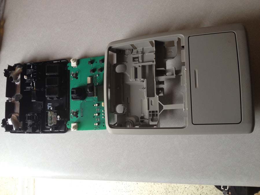
CB2775AHL5
Apr 29, 2013Universal Garage Door Opener w/ FHSS TX
Equipment Class
DSR - Part 15 Remote Control/Security Device Transceiver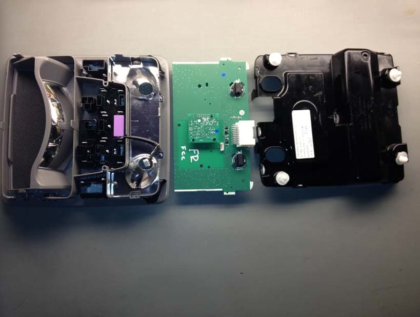
CB2440AHL5
Feb 24, 2013Universal Garage Door TX w/ FHSS TX
Equipment Class
DSS - Part 15 Spread Spectrum Transmitter