CCT71577Infant-to-Toddler Monitor Model 71577
Fisher-Price Inc.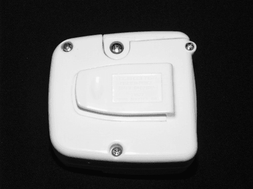
Click to zoom
Application Details
- Equipment Class
- DXX - Part 15 Low Power Communication Device Transmitter
- Date of Grant
- Jul 19, 1999
- Application Purpose
- Original Equipment
- Date of Application
- Jun 06, 1999
- Equipment Note
- Infant-to-Toddler Monitor Model 71577
- Frequency Range
- 906.00000000 - 906.66668800
- Company
- Fisher-Price Inc.
- Country
- United States
Documents & Files
Document Text
Text extracted from the exhibit documents filed with the FCC. Open a document above to read the original.
Attestation Statements
Interoffice Memo DATE:May 25, 1999COPIES: TO:Criterion Technology Barry Whallen, Laboratory Director FROM:Karen Fitzgerald SUBJECT:FCC and Industry Canada filing for Fisher Price Monitor #71577 Criterion Technology is authorized to act as Fisher Price agent for the purpose of obtaining FCC and Industry Canada certification for Fisher Price Baby Monitor model 71577. Karen Fitzgerald Sr. Project Engineer Fisher Price 636 Girard Avenue East Aurora, NY, 14052 (716) 687-3270
Block Diagram
- Infant to Toddler Monitor A 11 Friday , June 04, 1999 Tit leSize Document Number Rev Date: Sheet of Vcc S1 14.15625MHz 14.166667MHz R Limiting Amp 3 2 AMP 3 2 MICROPHONE x2 32 X32 PLL Div ideBy 32 Div ideBy 8 Voltge Controlled Crystal Oscillator Not Used Loop Antenna RFMD 9901 906BandPassFilter ~ "Block Diagram" Fisher-Price 636 Girard Av e. East Aurora, N.y . 14052 906.6666 MHz 453.333MHz
Cover Letter(s)
Reviewing Engineer Federal Communications Commission Office of Engineering and Technology 445 12 th Street S.W. Washington, D.C. 20554 Mike Mussler Criterion Technology PO Box 387 1350 County Road 16 Rollinsville, CO 80474 E-Mail: [email protected] 8 June 1999 Dear Sir/Madam, Please direct your attention to an error in test report number FPT99052401 for the Fisher Price Infant-to- Toddler Monitor Model 71577, confirmation number EA94438 that appears on sheets 7, 43 and 44. The report should reference Part 15 Paragraph 15.249, not 15.247. A replacement PDF version of the report has been submitted as an exhibit (FPT99052401_a) that corrects the error. Please retain the replacement report for the application and note that Item 10 on FCC Form 731 should read: “Equipment will be operated under FCC Rule Part(s): 15.249.” Please accept my apology for any confusion that my error may have caused. Sincerely, Mike Mussler
External Photos
Transmitter, External Front View Transmitter, External Rear View Transmitter External Power Supply Transmitter With External Power Supply
ID Label/Location Info
Transmitter ID Label ID Label Location
Internal Photos
Transmitter, Battery Compartment View Transmitter, Partially Disassembled Transmitter, Component Side of PWB Transmitter, Foil Side of PWB
Operational Description
Circuit description of monitor Transmitter The transmitter is a narrow band FM transmitter for the 900 Mhz ISM band. A crystal oscillator is modulated with a varactor diode to generate a 14 mhz reference signal. This frequency can changed to a different channel by a switch that changes crystals. This signal is then multiplied to 453 Mhz with a divided Phase Locked Loop. The 453 Mhz signal is multiplied by 2 with a rectifying circuit. The output of the X2 circuit has components at Fo/2 and Fo*3/2. These are then filtered with a PC board bandpass filter The output then is inductively coupled to a loop antenna made from a metal strap and trimmed with a small cap. There is a divider inside the chip that is not used in this circuit that produces spurious outputs at about +- 1.8 Mhz offsets from the carrier. These are inside the ISM band. Spurious outputs from the transmitter are at: Fo = output frequency = crystal frequency X 64 Fc = crystal frequency: Channel 1, 14.15625 Mhz Channel 2, 14.166667 Mhz 1 Fo+- (Fc) (2*Fc) (3*fc) ... PLL reference spurs 2 Fo/2 X2 spur 3 Fo*3/2 X2 spur 4 Fo+- (Fc/8) (Fc*2/8) ... unused divide by 8 spur Receiver The receiver is a standard Superhet design with a 10.7 Mhz IF and high side LO injection. The LO and its harmonics are the only signals that should be visible from the receiver. Channel 1 Flo= 916.7Mhz Channel 2 Flo=917.366667Mhz
Schematics
A A B B C C D D E E 44 33 22 11 W=50 W=50 W=50 W=50 1008 SIZE LOAD ONLY ONE SMT (D2A) OR THRU HOLE (D2B) WIRE-TO LEADS TO MIC {Doc}{RevCode} 900 MHz monitor transmitter B 12Tuesday, May 25, 1999 Title SizeDocument NumberRev Date:Sheet of C3 47p R8 1.5KR R1 27k L1 22nH Y1 14.166667MHZ L4 22nH U2 RFMD9901 1 2 3 4 5 6 7 89 10 11 12 13 14 15 16 OSC B OSC E NC GND CNTR MOD PC BG-OUTRF OUT GND VCC VCC GND GND RES2 RES1 L2 6.8uH C4 47p L3 100NH C2 47P R5 51R L5 18nH C16 2.2p C17 2.2p C15 2.2p C18 2.2p C14 2.2p C19 2.2p C9 .1uF R6 10R C11 47P C10 .1uF C5 .01uF R9 1.8k C12 100pF C6 .1uF R4 100k L6 15nH + - U3B LM358 5 6 7 8 4 + - U3A LM358 3 2 1 8 4 R17 2.2k R10 51 R21 100k C23 .1uF C24 .1uF R18 51k C26 .1uF R12 100k R13 100k+C20 47uF R11 100k R15 100k R14 510k R20 1meg R22 10k C27 .1uF C21 .1uF R23 1k Y2 14.156250MHZ +C8 10uF R3 5.6k R2 5.6k + C22 1uF R19 10k + C25 10uF C7 47P U1 TK11930 1 2 34 5 6 BP EN RESETVOUT GND VIN R7 510 J1 PHONEJACK 3 2 1 R24100R C1 10uF +BAT WIRE-TO 1 BAT WIRE-TO 1 MIC1 WIRE-TO 1 MIC2 WIRE-TO 1 D2B LED, RED, THRUHOLE, OPTION D1 IT369 D4 BAS21 D3 BAS21 Q1 MMBT3904 S1 SW SPDT S2 SW SPDT R27 10k R26 1k Q2 MMBT3904 R25 10k C28 CNL C13 2200pF R29 150R R28 150R C29 1000pF ANT1 TX-ANTENNA 1 2 3 4 GND IN GND CAP C30 1.5-3p C31 CNL A A B B C C D D E E 44 33 22 11 10-21-98 change C13 from .01uf to 2200pf C3 from 150pf to 82pf R21 from 1meg to 100k change electrolytic caps from surface mount to thru-hole added to silktop and photo text; -->add pn 71577-9609 to PCB and film title block chg L3 to 0805 pkg for larger inductor-->kept in same loc slight ovelap ok crit. area can't get ecap c22 -- too tight into thruhole! CHANGE made by Rich(PCB) and Steve (EE) 10-29-98 Rush to china SAT morn Netlist crashed due to "-BAT" chg to "BAT" and it works. Fix C22 is SMT electrolytic chg to THRUhole, missed before now D6,7 gone space avail. R16 - no load, short nets across D5,d6 and remove, c4=27pf, c5=39pf, L2=6.8uh. Q1 and Q2 pinout wrong on PCB s/b: (from tab, top-view, clockwise pins from tab= C-E-B). C2 c5 == plane gnd vias missing off ends. C17, c18 = dual gnd vias missing 1 gone each, restore. C13 changes to 0603 package from electrolytic. Net topology: is: R5->L3->c2->c5 should be: R5->C2->C5->L3 (R=non-lumped design) changed part number to 71577-9609a and date to 10/29/98 on film {Doc}{RevCode} {Title} A 22Friday, January 01, 1999 Title SizeDocument NumberRev Date:Sheet of
Test Report
TEST REPORT June 4, 1999 10:56 amFPT 9905 2401 Page 1 of 44 CONFIDENTIAL AND PROPRIETARY QUALIFICATION TEST REPORT EMISSIONS -FCC Part 15 Test Report Number:FPT9905 2401 Date of Issue: 3 June 1999 Model No: 71577 Infant to Toddler Monitor Date of Test Article Receipt: 25 May 1999 Type of product: Part 15.249 Intentional Radiator, Part 15 Subpart B Unintentional Radiator Manufacturer:Fisher Price Address:636 Girard Avenue East Aurora, New York 14052 Test Results:[X] Complies[ ] Does Not Comply __________R. Barry Wallen______________Lab Director (NVLAP Signatory) __________Michael Mussler _____________Compliance Engineer Accredited by NIST NVLAP for FCC Part 15 Accredited Since 1993 TEST REPORT June 4, 1999 10:56 amFPT 9905 2401 Page 2 of 44 CONFIDENTIAL AND PROPRIETARY Disclaimers: This report is the confidential property of the client. For the protection of our clients and ourselves, extracts from this test report cannot be produced without prior written approval from Criterion Technology. Reproduc- tion of the complete report can be performed at the client’s discretion. The client is aware that Criterion Technology has performed testing in accordance with the applicable stan- dard(s). Test data is accurate within ANSI parameters for Emissions testing, unless a specific level of accuracy has been defined in writing prior to testing, by Criterion Technology and the client. Criterion Technology reports apply only to the specific Equipment Under Test (EUT) sample(s) tested under the test conditions described in this report. If the manufacturer intends to use this report as a document demon- strating compliance of this model, additional models of this product must have electrical and mechanical char- acteristics identical to the device tested for this report. Criterion Technology shall have no liability for any deductions, inferences, or generalizations drawn by the client or others from Criterion Technology issued reports. Total liability is limited to the amount invoiced for the testing of this EUT and the contents of this report are not warranted. Compliance with the appropriate governmental standards is the responsibility of the manufacturer. Any questions regarding this report should be directed to: Laboratory Director Criterion Technology P.O. Box 387 1350 County Road 16 Rollinsville, Colorado 80474 Phone: 1-303-682-6600 Fax:1-303-682-6672 email: [email protected] NVLAP Notes: The NVLAP Logo on the front cover of this report applies only to the 47 CFR part 15 and CISPR 22:1993 data contained herein. This report contains data which are not covered by the NVLAP accreditation. This report must not be used by the client to claim product endorsement by NVLAP or any agency of the U.S. Government. Criterion Technology has been accredited by the following groups: NVLAP, VCCI, BCIQ, NMi (EU Compe- tent Body Accreditation) and Industry Canada. All Criterion Technology instrumentation and accessories used to test products for compliance to the indicated standards are calibrated regularly in accordance with ISO 9001, ISO Guide 25, ANSI/NCSL Z540-I-1994 and are traceable to national standards. TEST REPORT June 4, 1999 10:56 amFPT 9905 2401 Page 3 of 44 CONFIDENTIAL AND PROPRIETARY Table of Contents Section 1Executive Summary . . . . . . . . . . . . . . . . . . . . . . . . . . . . . . 5 Section 2Emissions Test Standards . . . . . . . . . . . . . . . . . . . . . . . . . . 7 Part 2.1 FCC Part 15 Subpart B - Conducted Emissions . . . . . . . . . . . . . . . . . . . . . . . . . . . . . . . . . . . . . . . 8 Part 2.2FCC Part 15 Subpart B –Radiated Emissions. . . . . . . . . . . . . . . . . . . . . . . . . . . . . . . . . . . . . . . . . . 9 Part 2.3 FCC Part 15 Subpart C –Intentional Radiated Fields. . . . . . . . . . . . . . . . . . . . . . . . . . . . . . . . . . . 11 Section 3Test Setup Photographs. . . . . . . . . . . . . . . . . . . . . . . . . . . 13 Part 3.1 Conducted Emissions Setup - Front View . . . . . . . . . . . . . . . . . . . . . . . . . . . . . . . . . . . . . . . . . . . 13 Part 3.2 Conducted Emissions Setup - Side View . . . . . . . . . . . . . . . . . . . . . . . . . . . . . . . . . . . . . . . . . . . . 14 Part 3.3 Radiated Emissions Setup - 30 Mhz to 10 GHz, Front View . . . . . . . . . . . . . . . . . . . . . . . . . . . . 15 Part 3.4 Radiated Emissions Setup - 30 MHz to 10 GHz, Rear View . . . . . . . . . . . . . . . . . . . . . . . . . . . . 16 Part 3.5 Radiated Emissions, 1 MHz to 30 MHz Setup. . . . . . . . . . . . . . . . . . . . . . . . . . . . . . . . . . . . . . . . 17 Section 4External and Internal Photos of the EUT . . . . . . . . . . . . . 19 Part 4.1 Receiver with External Power Supply . . . . . . . . . . . . . . . . . . . . . . . . . . . . . . . . . . . . . . . . . . . . . . 20 Part 4.2 Receiver, External Front View . . . . . . . . . . . . . . . . . . . . . . . . . . . . . . . . . . . . . . . . . . . . . . . . . . . . 21 Part 4.3 Receiver, External Rear View. . . . . . . . . . . . . . . . . . . . . . . . . . . . . . . . . . . . . . . . . . . . . . . . . . . . . 22 Part 4.4 Receiver, Battery Compartment . . . . . . . . . . . . . . . . . . . . . . . . . . . . . . . . . . . . . . . . . . . . . . . . . . . 23 Part 4.5 Receiver, Partially Disassembled . . . . . . . . . . . . . . . . . . . . . . . . . . . . . . . . . . . . . . . . . . . . . . . . . . 24 Part 4.6 Receiver, Component Side of PWB . . . . . . . . . . . . . . . . . . . . . . . . . . . . . . . . . . . . . . . . . . . . . . . . 25 Part 4.7 Receiver, Foil Side of PWB . . . . . . . . . . . . . . . . . . . . . . . . . . . . . . . . . . . . . . . . . . . . . . . . . . . . . . 26 Part 4.8 Transmitter, External Front View. . . . . . . . . . . . . . . . . . . . . . . . . . . . . . . . . . . . . . . . . . . . . . . . . . 27 Part 4.9 Transmitter, External Rear View . . . . . . . . . . . . . . . . . . . . . . . . . . . . . . . . . . . . . . . . . . . . . . . . . . 28 Part 4.10 Transmitter, Battery Compartm…
Text truncated - open the document above for the full version.
Test Report
TEST REPORT June 8, 1999 2:00 pmFPT 9905 2401 Page 1 of 44 CONFIDENTIAL AND PROPRIETARY QUALIFICATION TEST REPORT EMISSIONS -FCC Part 15 Test Report Number:FPT9905 2401 Date of Issue: 3 June 1999 Model No: 71577 Infant to Toddler Monitor Date of Test Article Receipt: 25 May 1999 Type of product: Part 15.249 Intentional Radiator, Part 15 Subpart B Unintentional Radiator Manufacturer:Fisher Price Address:636 Girard Avenue East Aurora, New York 14052 Test Results:[X] Complies[ ] Does Not Comply __________R. Barry Wallen______________Lab Director (NVLAP Signatory) __________Michael Mussler _____________Compliance Engineer Accredited by NIST NVLAP for FCC Part 15 Accredited Since 1993 TEST REPORT June 8, 1999 2:00 pmFPT 9905 2401 Page 2 of 44 CONFIDENTIAL AND PROPRIETARY Disclaimers: This report is the confidential property of the client. For the protection of our clients and ourselves, extracts from this test report cannot be produced without prior written approval from Criterion Technology. Reproduc- tion of the complete report can be performed at the client’s discretion. The client is aware that Criterion Technology has performed testing in accordance with the applicable stan- dard(s). Test data is accurate within ANSI parameters for Emissions testing, unless a specific level of accuracy has been defined in writing prior to testing, by Criterion Technology and the client. Criterion Technology reports apply only to the specific Equipment Under Test (EUT) sample(s) tested under the test conditions described in this report. If the manufacturer intends to use this report as a document demon- strating compliance of this model, additional models of this product must have electrical and mechanical char- acteristics identical to the device tested for this report. Criterion Technology shall have no liability for any deductions, inferences, or generalizations drawn by the client or others from Criterion Technology issued reports. Total liability is limited to the amount invoiced for the testing of this EUT and the contents of this report are not warranted. Compliance with the appropriate governmental standards is the responsibility of the manufacturer. Any questions regarding this report should be directed to: Laboratory Director Criterion Technology P.O. Box 387 1350 County Road 16 Rollinsville, Colorado 80474 Phone: 1-303-682-6600 Fax:1-303-682-6672 email: [email protected] NVLAP Notes: The NVLAP Logo on the front cover of this report applies only to the 47 CFR part 15 and CISPR 22:1993 data contained herein. This report contains data which are not covered by the NVLAP accreditation. This report must not be used by the client to claim product endorsement by NVLAP or any agency of the U.S. Government. Criterion Technology has been accredited by the following groups: NVLAP, VCCI, BCIQ, NMi (EU Compe- tent Body Accreditation) and Industry Canada. All Criterion Technology instrumentation and accessories used to test products for compliance to the indicated standards are calibrated regularly in accordance with ISO 9001, ISO Guide 25, ANSI/NCSL Z540-I-1994 and are traceable to national standards. TEST REPORT June 8, 1999 2:00 pmFPT 9905 2401 Page 3 of 44 CONFIDENTIAL AND PROPRIETARY Table of Contents Section 1Executive Summary . . . . . . . . . . . . . . . . . . . . . . . . . . . . . . 5 Section 2Emissions Test Standards . . . . . . . . . . . . . . . . . . . . . . . . . . 7 Part 2.1 FCC Part 15 Subpart B - Conducted Emissions . . . . . . . . . . . . . . . . . . . . . . . . . . . . . . . . . . . . . . . 8 Part 2.2FCC Part 15 Subpart B –Radiated Emissions. . . . . . . . . . . . . . . . . . . . . . . . . . . . . . . . . . . . . . . . . . 9 Part 2.3 FCC Part 15 Subpart C –Intentional Radiated Fields. . . . . . . . . . . . . . . . . . . . . . . . . . . . . . . . . . . 11 Section 3Test Setup Photographs. . . . . . . . . . . . . . . . . . . . . . . . . . . 13 Part 3.1 Conducted Emissions Setup - Front View . . . . . . . . . . . . . . . . . . . . . . . . . . . . . . . . . . . . . . . . . . . 13 Part 3.2 Conducted Emissions Setup - Side View . . . . . . . . . . . . . . . . . . . . . . . . . . . . . . . . . . . . . . . . . . . . 14 Part 3.3 Radiated Emissions Setup - 30 Mhz to 10 GHz, Front View . . . . . . . . . . . . . . . . . . . . . . . . . . . . 15 Part 3.4 Radiated Emissions Setup - 30 MHz to 10 GHz, Rear View . . . . . . . . . . . . . . . . . . . . . . . . . . . . 16 Part 3.5 Radiated Emissions, 1 MHz to 30 MHz Setup. . . . . . . . . . . . . . . . . . . . . . . . . . . . . . . . . . . . . . . . 17 Section 4External and Internal Photos of the EUT . . . . . . . . . . . . . 19 Part 4.1 Receiver with External Power Supply . . . . . . . . . . . . . . . . . . . . . . . . . . . . . . . . . . . . . . . . . . . . . . 20 Part 4.2 Receiver, External Front View . . . . . . . . . . . . . . . . . . . . . . . . . . . . . . . . . . . . . . . . . . . . . . . . . . . . 21 Part 4.3 Receiver, External Rear View. . . . . . . . . . . . . . . . . . . . . . . . . . . . . . . . . . . . . . . . . . . . . . . . . . . . . 22 Part 4.4 Receiver, Battery Compartment . . . . . . . . . . . . . . . . . . . . . . . . . . . . . . . . . . . . . . . . . . . . . . . . . . . 23 Part 4.5 Receiver, Partially Disassembled . . . . . . . . . . . . . . . . . . . . . . . . . . . . . . . . . . . . . . . . . . . . . . . . . . 24 Part 4.6 Receiver, Component Side of PWB . . . . . . . . . . . . . . . . . . . . . . . . . . . . . . . . . . . . . . . . . . . . . . . . 25 Part 4.7 Receiver, Foil Side of PWB . . . . . . . . . . . . . . . . . . . . . . . . . . . . . . . . . . . . . . . . . . . . . . . . . . . . . . 26 Part 4.8 Transmitter, External Front View. . . . . . . . . . . . . . . . . . . . . . . . . . . . . . . . . . . . . . . . . . . . . . . . . . 27 Part 4.9 Transmitter, External Rear View . . . . . . . . . . . . . . . . . . . . . . . . . . . . . . . . . . . . . . . . . . . . . . . . . . 28 Part 4.10 Transmitter, Battery Compartment…
Text truncated - open the document above for the full version.
Test Setup Photos
Conducted Emissions, Front View Conducted Emissions, Side View Radiated Emissions, 30 MHz to 10 GHz, Front View Radiated Emissions, 30 MHz to 10 GHz, Rear View Radiated Emissions, 1.5 to 30 MHz
Contact Information
Applicant
Jerry Miller(Quality Staff Engineer)
Technical Contact
Fisher Price Inc.Karen Fitzgerald
[email protected](716) 687-3270
636 Girard Ave. · East Aurora, New York · United States
Test Firm
Criterion Technology Corp.Lou Schornack
Technical Specifications
| # | Rule Parts | Frequency Range | Power Output |
|---|---|---|---|
| 1 | 15C | 906 MHz - 906.666688 MHz | - |
Other Applications from Fisher-Price Inc.

CCT-DNV31-15
Sep 29, 2015Smart Toy Bear (DNV31), Smart Toy Panda (DNV30), Smart Toy Monkey (DNV32)
Equipment Class
DXX - Part 15 Low Power Communication Device Transmitter
CCT-CBV76-14
Jun 22, 2014Mattel Bluetooth Low Energy Module
Equipment Class
DTS - Digital Transmission System
CCTT4841T-10
Jul 27, 2010Digital Audio Monitor (Baby Unit)
Equipment Class
DSS - Part 15 Spread Spectrum Transmitter
CCTT4256T-10
Jul 22, 2010Digital Video Monitor (Baby Unit)
Equipment Class
DSS - Part 15 Spread Spectrum Transmitter
CCTT4256R-10
Jul 21, 2010Digital Video Monitor (Parent Unit)
Equipment Class
DSS - Part 15 Spread Spectrum Transmitter