CCT71636Baby Monitor
Fisher-Price Inc.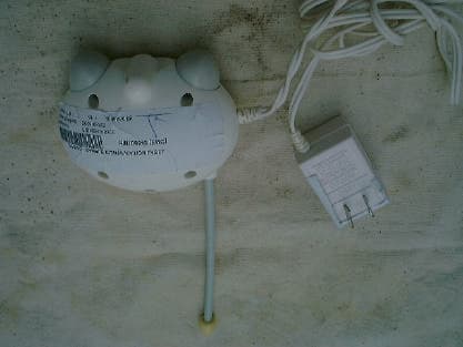
Click to zoom
Application Details
- Equipment Class
- DXT - Part 15 Low Power Transceiver, Rx Verified
- Date of Grant
- Sep 06, 2001
- Application Purpose
- Original Equipment
- Date of Application
- Sep 06, 2001
- Equipment Note
- Baby Monitor
- Frequency Range
- 49.82000000 - 49.90000000
- Company
- Fisher-Price Inc.
- Country
- United States
Documents & Files
Document Text
Text extracted from the exhibit documents filed with the FCC. Open a document above to read the original.
Users Manual
Prenatal Sounds Monitor Model Number: 71591 w w w . f i s h e r - p r i c e . c o m For proper setup and use, please read these instructions and keep for future reference. Includes two AC adaptors to power transmitter and receiver (plugs into standard household outlets –120V AC). Receiver also runs on battery power (9V alkaline battery – not included). Adult assembly is required to install the battery (if used). Note Consumer Information Occasionally a consumer may experience a problem with one of our products. If this should happen, please call us toll-free, rather than return this product to the store. Usually, we can solve the problem over the telephone or send you replacement parts. Please call Fisher-Price® Consumer Relations, toll-free at 1-800-432-KIDS, between 8 AM - 6 PM EST, Monday through Friday. Hearing-impaired consumers using TTY/TDD equipment, please call 1-800-382-7470. Or write to: Fisher-Price® Consumer Relations 636 Girard Avenue East Aurora, New York 14052 2 Important! This product cannot replace responsible adult supervision. CAUTION • This product is not intended to be used as a medical monitor and its use should not replace adult supervision. • Test sound reception of receiver before first-time use and whenever you change location of transmitter. • To prevent entanglement: - Never place transmitter in a crib or playpen. Keep transmitter and receiver out of baby’s reach. - Never use extension cords with the AC adaptors. • Never use transmitter or receiver near water (ie.: bathtub, sink, laundry tub or wet basement, etc.). • Always use transmitter and receiver where there is adequate ventilation. To prevent overheating, keep transmitter and receiver away from heat sources such as radiators, heat registers, direct sunlight, stoves, amplifiers, or other appliances which produce heat. 3 Receiver Battery Installation (Optional) Battery Compartment Door 9V (6LR61) SHOWN ACTUAL SIZE 4 Receiver Battery Installation (Optional) Battery Tips • Remove the battery during long periods of non-use. Always remove an exhausted battery from the product. Battery leakage and corrosion can damage this product. Dispose of battery safely. • Do not dispose of batteries in a fire. The batteries may explode or leak. • Never short circuit the battery terminals. • A non-rechargeable battery is not to be recharged. • Only a battery of the same or equivalent type as recommended in the “Battery Installation” instructions is to be used. • If a removable rechargeable battery is used, it is only to be charged under adult supervision. • A rechargeable battery is to be removed from the product before it is charged. • If you use a battery charger, it should be examined regularly for damage to the cord, plug, enclosure and other parts. Do not use a damaged battery charger until it has been properly repaired. • Locate battery compartment door on bottom of receiver. • Push finger tab on battery compartment door to open battery compartment door. • Snap terminals of a fresh, 9V alkaline battery into receiver connectors. • Close battery compartment door. 5 Testing Sound Reception Test transmitter transmission and receiver reception. Place transmitter in room in which you intend to use it. Slide transmitter power switch to turn power on. Turn on a radio. If you experience interference (buzzing or static, etc.) while using one channel setting, switch bothunits to other channel. Selecting a channel is usually a one time adjustment. 6 Testing Sound Reception Place receiver in room in which you intend to use it. Rotate on/off/volume dial to turn power on. Adjust receiver location. Notes: • Variable light display lights when sound is received by receiver. • If all five bars in variable light display light: - Receiver power is on and transmitter power is off. - Receiver is too far away from transmitter. - Receiver and transmitter are not on same channel. - Loud sounds are transmitting. Hint:If you turn receiver power on before transmitter power, you will hear a static noise and all five bars in variable light display light. Simply turn volume down and turn transmitter power on. 7 Setup and Use 8 1 4 3 1 7 3 2 6 5 Setup and Use IMPORTANT!Test sound reception of this monitor before first time use and whenever you change location of transmitter (see page X). Set transmitter channel switch to same channel as receiver. Place transmitter in same room with child. Point microphone directly toward crib or play area. Unwrap and fully extend AC adaptor cord for best transmission. Insert AC adaptor jack into transmitter socket and plug into wall outlet. Slide transmitter on/off switch to turn power on. Power indicator lights. Place receiver where you will see or hear it. Unwrap and fully extend AC adaptor cord for best reception. Insert AC adaptor jack into receiver socket and plug into wall outlet. Note:To use a 9V alkaline battery for power source, refer to “Receiver Battery Installation” instructions on this page. Rotate receiver on/off/volume dial to turn power on. Power indicator lights. Rotate on/off/volume dial to adjust volume . 1 2 3 4 5 6 7 9 Problems and Solutions 1 Circuit Breaker 10 2 6 2 1 2 3 5 4 “Ma, Mah, Da, Da...” BUZZZZ BUZZZZZ BUZZZZZ Problems and Solutions Transmitter power off. Power indicator not lit. You hear static or buzzing because transmitter channel switch is not on same channel as receiver. Transmitter power off. Power indi- cator not lit. Light switch that con- trols power flow to wall outlet off. Transmitter power off. Power indicator not lit. AC adaptor cord plug-to-outlet not connected. Transmitter power off. Power indi- cator not lit. Power is off because circuit breaker for baby’s room off. You hear static or buzzing and all five bars lit on receiver. PROBLEMS SOLUTIONS Turn transmitter power on. Power indicator lights. Make sure channel switches on both transmitter and receiver set to same channel. Make sure light switch that controls power flow to wall outlet is on. Check AC adaptor cord pl…
Text truncated - open the document above for the full version.
External Photos
FCC ID: CCT71636 PHOTOGRAPH OF THE PRODUCT FRONT VIEW OF THE PRODUCT REAR VIEW OF THE PRODUCT
ID Label/Location Info
FISHER-PRICE CANADA 210 FCC ID: CCT71636 MADE IN CHINA This device complies with part 15 of the FCC Rules. Operation is subject to the following two conditions: (1) this device may not cause harmful interference, and (2) this device must accept any interference received, including interference that may cause undesired operation.
ID Label/Location Info
FCC ID: CCT71636 LABEL LOCATION BOTTOM VIEW OF THE DEVICE WITH FCC ID LABEL FISHER-PRICE CANADA 210 FCC ID: CCT71636 MADE IN CHINA This device complies with part 15 of the FCC Rules. Operation is subject to the following two conditions: (1) this device may not cause harmful interference, and (2) this device must accept any interference received, including interference that may cause undesired operation. FCC ID LABEL
Internal Photos
FCC ID: CCT71636 PHOTOGRAPH OF THE PRODUCT INNER CIRCUIT TOP VIEW INNER CIRCUIT BOTTOM VIEW
Operational Description
FCC ID: CCT71636 Circuit Description The (16.623833MHz x 3 to Channel A 49.84MHz & Channel B 49.89MHz) crystal oscillator drives the base of Q1 the final/buffer amplifier. The modulation provided by Mic. The output of Q1 has the matching network consisting of L1 and C1 that limit the harmonic content and effect the proper coupling of the antenna to the output stage. Antenna, Ground and Power Source The antenna consists of a 16cm long metal wire. There is no external ground connection. The ground is only that of the printed circuit board. Electric current is supplied by a 6 Volt (“AC adapter 117Va.c.)
Test Report
Date: 2001-08-13 TEST REPORT Page 1 of 24 No.: HM105543 FCC PART 15 SUBPART C CERTIFICATION REPORT FOR LOW POWER TRANSMITTER TEST REPORT No.:HM105543 Equipment Under Test [EUT]:Prenatal to infant monitor Model Number:71636 Applicant:FISHER-PRICE FCC ID :CCT71636 Date: 2001-08-13 TEST REPORT Page 2 of 24 No.: HM105543 CONTENT: Cover Page 1 of 24 Content Page 2-3 of 24 Conclusion Page 4 of 24 1.0General Details 1.1Test Laboratory Page 5 of 24 1.2Applicant Details Page 5 of 24 Applicant HKSTC Code Number for Applicant Manufacturer 1.3Equipment Under Test [EUT] Page 6 of 24 Description of EUT operation 1.4Date of Order Page 6 of 24 1.5Submitted Sample Page 6 of 24 1.6Test Duration Page 6 of 24 1.7Country of Origin Page 6 of 24 1.8 Additional Information of EUT Page 7 of 24 2.0Technical Details 2.1Investigations Requested Page 8 of 24 2.2Test Standards and Results Summary Page 8 of 24 3.0Test Results 3.1Emission Page 9-19 of 24 3.2Bandwidth Measurement Page 20-21 of 24 Date: 2001-08-13 TEST REPORT Page 3 of 24 No.: HM105543 Appendix A List of Measurement Equipment Page 22 of 24 Appendix B Photographs Page 23-24 of 24 Date: 2001-08-13 TEST REPORT Page 4 of 24 No.: HM105543 CONCLUSION The submitted product was deemed to have COMPLIED with the requirements of Federal Communications Commission [FCC] Rules and Regulations Part 15. The tests were performed in accordance with the standards described above and on Section 2.2 in this Test Report. Verify byPatrick Wong for Managing Director Date: 2001-08-13 TEST REPORT Page 5 of 24 No.: HM105543 1.0General Details 1.1Test Laboratory The Hong Kong Standards and Testing Centre Ltd. EMC Laboratory 10 Dai Wang Street, Taipo Industrial Estate New Territories, Hong Kong Telephone:852 2666 1888 Fax:852 2664 4353 1.2Applicant Details Applicant FISHER-PRICE 636 GIRARD AVENUE, EAST AURORA, NY, USA Telephone:31856612 Fax:23170618 HKSTC Code Number for ApplicantFIP003 Manufacturer EXCEL ENGINEERING CO., LTD. Rm. 306, Lippo Sun Plaza, 18 Canton Road, Tsim Sha Tsui, Kowloon, Hong Kong Telephone:852 2736 3632 Fax:852 2314 4424 Date: 2001-08-13 TEST REPORT Page 6 of 24 No.: HM105543 1.3Equipment Under Test [EUT] Description of Sample Product:Prenatal to infant monitor Manufacturer:Excel Engineering Co., Ltd. Brand Name:FISHER-PRICE Model Number:71636 Input Voltage:9Vd.c (“6F22” size battery x 1) with jack The AC/DC Adapter used for the tests was provided by the applicant with the following details: Model Number: DV-6050, Input: 120Va.c. 60Hz 4W, Output: 6Vd.c. 50mA Additional Model Number:71637 1.3.1Description of EUT Operation The Equipment Under Test (EUT) is an FISHER-PRICE., 49.89MHz Prentatal to infant monitor. The transmitter is a 2 button transmitter. The EUT continues to transmit while button is being pressed. It is voice transmission, Modulation by Mic. and tape is frequency modulation. 1.4Date of Order 2001-08-03 1.5Submitted Sample(s): 1 Sample per model 1.6Test Duration 2001-08-10 1.7Country of Origin China Date: 2001-08-13 TEST REPORT Page 7 of 24 No.: HM105543 1.8Additional Information of EUT SubmittedNot Available User Manual Part List Circuit Diagram Printed Circuit Board [PCB] Layout Rating Label Block diagram FCC ID Label Date: 2001-08-13 TEST REPORT Page 8 of 24 No.: HM105543 2.0Technical Details 2.1Investigations Requested Perform ElectroMagnetic Interference measurement in accordance with FCC 47CFR [Codes of Federal Regulations] Part 15 and ANSI C63.4:1992 for FCC Certification. 2.2Test Standards and Results Summary Tables EMISSION Results Summary Test ConditionTest RequirementTest MethodClass /Test Result SeverityPassFailedN/A Field Strength of Fundamental Emissions & Spurious Emissions FCC 47CFR 15.235ANSI C63.4:1992N/A Radiated Emissions, 30MHz to 1GHz FCC 47CFR 15.209ANSI C63.4:1992Class B Conducted Emissions on AC, 0.45MHz to 30MHz FCC 47CFR 15.207ANSI C63.4:1992Class B Note: N/A - Not Applicable Date: 2001-08-13 TEST REPORT Page 9 of 24 No.: HM105543 3.0Test Results 3.1Emission 3.1.1Radiated Emissions Test Requirement:FCC 47CFR 15.235 Test Method:ANSI C63.4:1992 Test Date:2001-08-10 Mode of Operation:On mode Test Method: The sample was placed 0.8m above the ground plane on the OATS *. Measurements in both horizontal and vertical polarities were performed. During the test, each emission was maximized by: having the EUT continuously working, investigate all operating modes, rotated about all 3 axis (X, Y & Z) to obtain worst position, manipulating interconnecting cables, rotating turntable, varying antenna height from 1m to 4m in both horizontal and vertical polarizations. The emissions worst-case are shown in Test Results of the following pages. *:OATS [Open Area Test Site] located at HKSTC with a metal ground plane on filed with the FCC pursuant to section 2.948 of the FCC rules, with Registration Number: 90657. Test Setup: EUT distance = 3m Pre -Amplifier Receiver Turn Table Computer Ground plane Date: 2001-08-13 TEST REPORT Page 10 of 24 No.: HM105543 Limits for Field Strength of Fundamental Emissions [FCC 47CFR 15.235]: Frequency Range of Fundamental Field Strength of Fundamental Emission [Peak] Field Strength of Fundamental Emission [Average] [MHz][μV/m][μV/m] 49.82-49.90100,00010,000 Results: Channel A Field Strength of Fundamental Emissions Peak Value FrequencyLevel @3mCorrection Factor Field Strength Field Strength Limit ** @3m Antenna Polarity MHzdBμVdB/mdBμV/mμV/mμV/m 49.8460.515.075.55,956.6100,000Vertical According to FCC 47CFR15.35, the limit on the radio frequency emissions as measured using instrumentation with a peak detector function, corresponding to 20dB above the maximum permitted average limit for the frequency being investigated unless a different peak emission limit is otherwise specified in the rules. Remarks: *:Linear interpolations Correction Factor included Antenna Factor and Cable Attenuation. Calculated measurement uncertainty=30MHz to 300MHz±3.7dB 300MHz to 1GHz+3.0dB / -2.7dB Date: 2001-08-13 TEST REPORT Page 11…
Text truncated - open the document above for the full version.
Test Report
FCC ID: CCT71636 September 5, 2001
Test Setup Photos
FCC ID: CCT71636 TEST SET UP PHOTOGRAPH OF THE PRODUCT MEASUREMENT OF RADIATED EMISSION TEST SET UP
Contact Information
Applicant
Jerry Miller(Quality Staff Engineer)
Test Firm
Hong Kong Standards & Testing Cen.Wilson Wong
Technical Specifications
| # | Rule Parts | Frequency Range | Power Output |
|---|---|---|---|
| 1 | 15C | 49.82 MHz - 49.9 MHz | - |
Other Applications from Fisher-Price Inc.

CCT-DNV31-15
Sep 29, 2015Smart Toy Bear (DNV31), Smart Toy Panda (DNV30), Smart Toy Monkey (DNV32)
Equipment Class
DXX - Part 15 Low Power Communication Device Transmitter
CCT-CBV76-14
Jun 22, 2014Mattel Bluetooth Low Energy Module
Equipment Class
DTS - Digital Transmission System
CCTT4841T-10
Jul 27, 2010Digital Audio Monitor (Baby Unit)
Equipment Class
DSS - Part 15 Spread Spectrum Transmitter
CCTT4256T-10
Jul 22, 2010Digital Video Monitor (Baby Unit)
Equipment Class
DSS - Part 15 Spread Spectrum Transmitter
CCTT4256R-10
Jul 21, 2010Digital Video Monitor (Parent Unit)
Equipment Class
DSS - Part 15 Spread Spectrum Transmitter