CCT71924RCar Seat Dashboard with Remote Control
Fisher-Price Inc.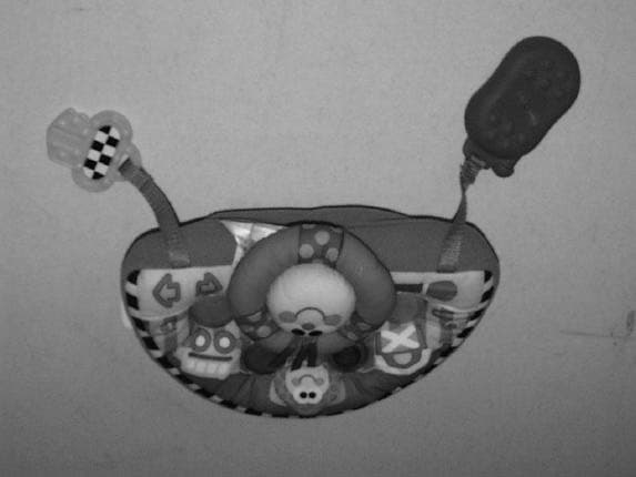
Click to zoom
Application Details
- Equipment Class
- CRR - Superregenerative Receiver
- Date of Grant
- May 01, 2000
- Application Purpose
- Original Equipment
- Date of Application
- Apr 21, 2000
- Equipment Note
- Car Seat Dashboard with Remote Control
- Frequency Range
- 344.90000000 - 345.10000000
- Company
- Fisher-Price Inc.
- Country
- United States
Documents & Files
Document Text
Text extracted from the exhibit documents filed with the FCC. Open a document above to read the original.
Users Manual
Car Seat Dashboard with Remote Control Model Number 71924 WARNING Please save these instructions for future reference. Batteries must be installed by an adult. Requires one 9 volt (6LR61) and three “AA” (LR6) alkaline batteries (not included). Tool required for battery installation: Phillips Screwdriver (not included). To prevent strangulation, never place product in a crib or playpen where baby could become entangled. NEVER add strings or ties to the product. Battery Compartment Dashboard Cover Battery Installation Battery Tips Hint:We recommend the use of alkaline batteries for longer battery life. 9V (6LR61) 1.5V X 3 “AA” (LR6) SHOWN ACTUAL SIZE SHOWN ACTUAL SIZE Battery Compartment Remote Control Dashboard • Turn the dashboard face down. Open the fasteners on the cover to locate the battery compartment on the dashboard. • Loosen the screws in the battery compartment door with a Phillips screwdriver. Remove the battery compartment door. • Insert three “AA” (LR6) alkaline batteries as indicated inside the battery compartment. • Replace the battery compartment door and tighten the screws with a Phillips screwdriver. Do not over-tighten. Remote Control • Loosen the screws in the battery compartment door with a Phillips screwdriver. Remove the battery compartment door. • Snap the contacts of a 9V (6LR61) alkaline battery to the contacts inside the battery compartment. • Replace the battery compartment door and tighten the screws with a Phillips screwdriver. Do not over-tighten. 2 Set-Up • Slide the power/volume control switch on to low volume . • Press the horn on the dashboard to activate the system. The lights will twinkle. The system will be on for approximately two hours. • Press the horn again to hear a soothing lullaby or entertaining song. Adjust the volume to a comfortable listening level for your child by either: - keeping the switch on low volume . - sliding the switch to high volume . Hint: Although the system is on, unless the toy is playing music or sound effects and lights are twinkling, only a very small amount of power is being used from the batteries. • Re-fasten the fasteners on the cover. Press horn to activate system. Power/ Volume Control Switch • Do not mix old and new batteries. • Do not mix different types of batteries: alkaline, standard (carbon-zinc) or rechargeable (nickel-cadmium). • Remove the batteries during long periods of non-use. Always remove exhausted batteries from the toy and remote. Battery leakage and corrosion can damage this toy. Dispose of batteries safely. • Never short circuit the battery terminals. • Non-rechargeable batteries are not to be recharged. • Only batteries of the same or equivalent type as recommended in the Battery Installation instructions are to be used. • If removable rechargeable batteries are used, they are only to be charged under adult supervision. • Rechargeable batteries are to be removed from the toy before they are charged. • If you use a battery charger, it should be examined regularly for damage to the cord, plug, enclosure and other parts. Do not use a damaged battery charger until it has been properly repaired. Attaching the Dashboard to a Car Seat IMPORTANT! This product is designed to attach to most car seats. If, after attaching this product to your car seat you find that you cannot properly tighten your car seat’s restraint system (as described in the car seat manufacturer’s instructions), DO NOT use this product on the car seat. • Position the dashboard upright with the horn facing baby. • Fasten the clips on the underside of the dashboard to the car seat bolster fabric, as shown. Clip Car Seat Bolster Fabric Dashboard Horn Car Seat with Bolster Before attaching the dashboard to your car seat’s restraint system, check to be sure the car seat restraint system is securing your child properly. Check all restraint system belts (shoulder, lap, crotch, etc.) by pulling on them. The straps should not pull more than one inch (two fingers) away from your child. • Position the dashboard so that the horn is upright and facing away from baby. • Wrap the dashboard straps around the crotch strap (of the car seat restraint system) and fasten. Horn Dashboard Car Seat Restraint System Car Seat with 3-Point or 5-Point Restraint 3 Adult Use with Remote Control • Press the horn on the dashboard to activate the system. The lights will twinkle. • Press the remote control button once for soothing lullabies and a light display. Music and lights plays for approximately three minutes. • To pause lullabies, press the remote control control button again. • To switch to entertaining songs, press the remote control button a third time. A musical selection and light display plays for approximately three minutes. • To pause songs, press the remote control button again. • To replay lullabies, press the remote control button again. Hint: Each time the remote control button is pressed, the toy will cycle between lullabies - pause - songs - pause, etc. Attaching the Remote Control To a Vehicle Visor • Attach the remote control clip to the top of the vehicle visor, as shown. Hint: The remote control does not need to be in direct line with dashboard. Visor Remote Control 4 Child Use with Dashboard Only • Press the horn on the dashboard to activate the system. The lights will twinkle. • When your child presses the horn, you’ll hear a sound effect. Then, your child will enjoy one soothing lullaby or entertaining song along with twinkling lights and a sound effect. Care Back View Front View Curved Edge • Once cleaned and dried, unfasten the fasteners on the underside of the cover. • Position the plastic unit so that the curved edge is toward the curved edge of the cover. • Fit the plastic unit into the cover. Re-fasten the cover fasteners closed. • Turn the dashboard upright. Fit the four lenses on the plastic unit through the four holes in the cover. Back View • Remove the plastic unit before washing the fabric dashboard cover. - Unfasten the fastene…
Text truncated - open the document above for the full version.
Block Diagram
71924 RC DASH RECEIVER BLOCK DIAGRAM (71924RxrevAblock) 4/ 4/00 PreampQ5 U1 Q7 Data slicerQ2 Q3 Q4 LP4 Q8-Q11 R7 SW2 VOL1/OFF/VOL2 Q12 SW1 STEERING WHEEL Super-regenOscillator Q8 C3 BT1 4.5V LS1 LP3 Low pass filter Q1 71924RXrevAblock A 71924 RC DASH RECEIVER BLOCK DIAGRAM (PER uP71924RxrevE.SCH,RF71924RxrevD.SCH) B 11 Wednesday, April 05, 2000 FISHER-PRICE 636 GIRARD AVE. EAST AURORA, N.Y. 14052 TitleSize Document Number Rev Date: Sheet of 3 V LP2 3 "AA" ANTENNA BULB DVRS 4 BIT CONTROLLER (U2) SPK DRIVER LP1 REGULATOR
External Photos
External Photograph of Fisher-Price Model RC Dash Receiver External Photograph of Fisher-Price Model RC Dash , Front (Covering Removed) External Photograph of Fisher-Price Model RC Dash, Rear (Covering Removed)
ID Label/Location Info
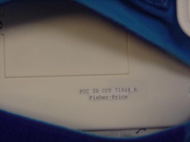
TOLERANCES - UNLESS OTHERWISE SPECIFIED - 3 PLACE DIMS ± .010 2 PLACE DIMS ± .020 FRACTION DIMS ± 1/32 ANGLES ± 2° DWN DATE SCALE DWG NO.CHG TITLE LET CHANGE BY DATE APPD *NOTE: REFER TO PART PRINT FOR DIMENSIONS Full MOLD MASTER (RAISE .015) 71924-N 3/24/00 ALAN MRUK 71924 RC Dash Location: Reciever FCC ID CCT 71924 R Fisher-Price
Internal Photos
Inside Front Cover Photograph of Fisher-Price Model RC Dash Receiver Inside Rear Cover Photograph of RC Dash Receiver Battery Compartment Photograph of Fisher-Price Model RC Dash Receiver Printed Wiring Board (Component Side) Photograph of Fisher-Price Model RC Dash Receiver Printed Wiring Board (Foil Side) Photograph of Fisher-Price Model RC Dash Receiver Antenna Photograph of Fisher-Price Model RC Dash Receiver
Operational Description
FISHER-PRICE 71924 RC DASH RECEIVER DESCRIPTION OF OPERATION Receiver Operation: The carseat attached receiver is controlled by a 4 bit micro-controller, allowing the unit to play music and flash lights to both soothe and entertain the child while in the confines of the carseat. Once initialized by sliding the ON/OFF Switch (SW2) to either one of the two volume modes from the center OFF position, and then depressing the Steering Wheel Switch (SW1), the receiver becomes activated and will respond to either a parent remote command or child interaction with SW1. If the receiver is inactive for the software-predefined period (approx. 2hrs) the unit will automatically turn off (time-out). The receiver is a low power Super-Regenerative design defined by components: R2, C2, R17, R21, C10, C18, Q6, L3, R22, C15, C9, C8, R7. An antenna preamp provides both RF gain as well as regen antenna isolation and is comprised of: R1, C1, Q5, R16, C11, C7, L2, R8, R6, C6. The regen stage (Q6) oscillates at 345MHz with a quench rate of 500KHz. A lowpass filter network defined by: R13, C13, R14, C14, R15, C12, R9, C24, Q1, R20 filters the high frequency RF regenerative components and buffers the data signal for eventual logic level squaring. Q2, Q3, Q4, C25, R12, R10, R3, R11, R4, R5, R19, R37, C17, R18, C4, C5 form an AC coupled comparator stage for squaring the low level data signal to logic levels for the micro-controller (U2). The data is then sent to U2 for detection and validation. System music, light patterns and data detection are controlled by the micro-controller. U1 regulates the 3”AA” +4.5V battery voltage to +3.0V for the RF receiver circuitry. Once the receiver is activated, the unit will go into a low current mode polling for either a parent remote command or a child press of the Steering Wheel Switch (SW1). If either a parent command or child interaction with SW1 occurs, the unit will execute music and light patterns. During execution of music and light patterns, a command from the parent remote unit will pause the unit turning off the music and lights. If no child interaction with SW1 occurs, the next received parent remote command prior to the timeout period will cause the unit to change to a new mode of music and lights. If a software predefined period of receiver inactivity results the unit will timeout and enter a low current mode until the next reinitialization by a depress of SW1. A total hardware OFF condition can be accomplished by moving SW2 to the OFF position disconnecting the batteries from the circuit. JPM, SE
Schematics
4/6/00 FIHSER-PRICE 71924 RC DASH RECEIVER SCHEMATIC (RF SECTION) C18 1000pF R181.5M +3V (FROM VOLTAGE REGULATOR) R15200k - Denotes wire terminal on PCB. * PCB FR-4 / G10 Q22N3904 R875k Q12N3904 C12 470pF * C1 1000pF DATA OUT (TO U2 P3.1) C170.22uF L1trace * C8 6pF C R91k Q5NE68133 R4200k R164.7k C2510uF ANT122AWG WIRE C9 1-3pF C9 = CERAMIC TRIMMER (High Stability) * C6 10pF * C5 0.1uF R2115k * C35pF * R5 200k 4). * Designates Capacitor as NPO. C240.1uF R1 100 R11 200k R7 4.7k 1) Resistors in OHMS, Capacitors in FARADS: unless otherwise noted. * C7 10pF * RF71924RxrevD.SCH D 71924 RC DASH RF SECTION - FINAL RELEASEFISHER-PRICE 636 GIRARD AVE. EAST AURORA, N.Y. 14052 Dwn by:B 11 Monday, March 27, 2000 TitleSize Document Number Rev Date: Sheet of R62k C4 0.1uF Q42N3904 R21k R10 200k B C14 1500pF C13 4700pF Q5 = ne68133, Q6 = ne94433CRITICAL COMPONENTS: C11 220pF R1320k * R191.5M C20.1uF L256nH Q6ne94433 +VCC (UNREGULATED) * R37 From 1.5M To 820k 3) Dashed or Dotted-Lined boxes indicates OFF-BOARD component(s). R7 From 10k To 4.7kCHANGES: C15 2pF C25: 0.1uF to 10uF (low leakage electrolytic) R1718k R14200k 2) * C17: 0.1uF to 0.22uF ceramic Q32N3904 R3 200k R1210k * Q4 Collector moved to Uregulated Voltage For Logic Leveling C16 2pF W15 * C8 From 8pF To 6pF R2010k R37820k R223.3k NOTES: C10 100pF L3390nH A R17 From 24k To 18k 4/6/00 FISHER-PRICES 71924 RC DASH RECEIVER SCHEMATIC (MICRO-CONTROLLER SECTION) R30 1k W15 W14 Q8JE9013G SW1 Steering Wheel MAX VOL U1+3V REGULATOR 2 3 1 VIN VOUT GND +3V (SUPPLY TO RF CIRCUITRY) LP4 W3 W10 R29 10k W12 R3922k Q12 JE8050D T0-92 Package Q9JE9013G 500Hz (2mS) REFERENCE TIMING C200.1uF Q13,R39,R40 to solve port impedance (KEYB) Q11JE9013G W7 NOTES: CHANGES: R23 10k to 510k, R24 1K to 10k 3) Dashed or Dotted-Lined boxes indicates OFF-BOARD component(s). R2410k 4.5V13 "AA" -+ LP2 R25910k SW2 123 876 4 5 C A LP1 - LP4 GOW Bulbs 100mA LP1 SW2 2P3T (On/OFF/Volume) CRITICAL COMPONENTS: LS1 16 ohm / 0.25W / 40mm LP3 + C19100UF + C21100UF R26 1k +VCC (UNREGULATED) ADDED: R38, B LS1 Speaker Size From 2.25in (57.15mm) To 1.57in (40mm). W2 W8 Q10JE9013G R23510k R41(volume reduction) ,R42(fine master clock adjustment if necessary) W9 W16 W13 PCB FR-4 / G10 R32 1k R25 From 1M to 910k, R42 From TBD to 56k. R41150 R38510k W4 MIN VOL uP71924RxrevE.SCH E 71924 RC DASH MICRO-PROCESSOR SECTION - FINAL RELEASE FISHER-PRICE 636 GIRARD AVE EAST AURORA, N.Y. 14052 Dwn by:B 11 Monday, March 27, 2000 TitleSize Document Number Rev Date: Sheet of W5 R3110k 1) Resistors in OHMS, Capacitors in FARADS: unless otherwise noted. R35390 Q12JE8050D R28 1k D1 1N4148 OFF R35 From 150 To 390 Q7 JE8550D 2) R3310k W1 DATA FROM RF DETECTOR CIRCUIT U2 EM57100 7 22 8 2321 91011121314151620191817 VDDOSCVOTESTVSS P3.3 P3.2P3.1P3.0P2.3P2.2P2.1P2.0P1.0P1.1P1.2P1.3 R4256k R364.7 Port 2 Changed LP1- LP4, Port 3 changed Pass Xter Predriver, RF DATA IN Q132N3904 + C23 220uF R40510k 4). * Designates Capacitor as NPO. R2710k R3412 W6 R25, R42 set for 500Hz (2mS) reference on P3.3 W11 C22 0.033uF U1 = Low Dropout +3V Regulator NJU7201U30 or equiv. D - Denotes wire terminal on PCB.
Test Report
TEST REPORT April 22, 2000 1:08 pmFCP 100032401 RX Page 1 of 22 CONFIDENTIAL AND PROPRIETARY QUALIFICATION TEST REPORT EMISSIONS -FCC Part 15 Test Report Number: FPT100032401 RX Date of Issue: 21 April 2000 Model No: RC Dash Receiver Date of Test Article Receipt: 28 March 2000 Type of product: FCC Part 15 Subpart B Manufacturer: Fisher-Price Address: 636 Girard Avenue East Aurora, N.Y. 14052 Test Results:[X] Complies[ ] Does Not Comply _____Michael E. Mussler _____________Lab Director (NVLAP Signatory) _____Michael E. Mussler_____________Compliance Engineer Accredited by NIST NVLAP for FCC Part 15 Accredited Since 1993 1350 County Road 16 P.O. Box 387 Rollinsville, CO 80474 (303) 258-0100 ph. (303) 258-0775 fax www.criteriontech.com C O R P . TEST REPORT April 22, 2000 1:08 pmFCP 100032401 RX Page 2 of 22 CONFIDENTIAL AND PROPRIETARY Disclaimers: This report is the confidential property of the client. For the protection of our clients and ourselves, extracts from this test report cannot be produced without prior written approval from Criterion Technology. Reproduction of the complete report can be performed at the client’s discretion. The client is aware that Criterion Technology has performed testing in accordance with the applicable standard(s). Test data is accurate within ANSI parameters for Emissions testing, unless a specific level of accuracy has been defined in writing prior to testing, by Criterion Technology and the client. Criterion Technology reports apply only to the specific Equipment Under Test (EUT) sample(s) tested under the test con- ditions described in this report. If the manufacturer intends to use this report as a document demonstrating compliance of this model, additional models of this product must have electrical and mechanical characteristics identical to the device tested for this report. Criterion Technology shall have no liability for any deductions, inferences, or generalizations drawn by the client or others from Criterion Technology issued reports. Total liability is limited to the amount invoiced for the testing of this EUT and the contents of this report are not war- ranted. Compliance with the appropriate governmental standards is the responsibility of the manufacturer. Any questions regarding this report should be directed to: Laboratory Director Criterion Technology P.O. Box 387 1350 County Road 16 Rollinsville, Colorado 80474 Phone: 1-303-682-6600 Fax:1-303-682-6672 email: [email protected] NVLAP Note: Criterion Technology is accredited by the National Voluntary Laboratory Accreditation Program (NVLAP) for the specific scope of accreditation under Lab Code 100396-0. Test methods included in Lab Code 100396-0 are: 1.12/CIS22 - IEC/CISPR22:1993 2.12/CIS22a - IEC/CISPR22:1993, Amendment1:1995 & Amendment2:1996 3.12/CIS22b - CNS13438:1997 4.12/F01 - FCC Method -47 Part 15 - Digital Devices 5.12/F01a - Conducted Emissions, Power Lines, 450 KHz to 30 MHz 6.12/F01b - Radiated Emissions 7.12/T51 - AS/NZS 3548 The NVLAP Logo on the front cover of this report applies only to data taken for the above test methods. This report may contain data which is not covered by the NVLAP accreditation. This report must not be used by the client to claim product endorsement by NVLAP or any agency of the U.S. Gov- ernment. Criterion Technology has been accredited by the following groups: NVLAP, VCCI, BSMI, NMi (EU Competent Body Accreditation) and Industry Canada. The National Institute for Standards and Technology (NIST) has designated Crite- rion Technology a Conformity Assessment Body (CAB) for Taiwan (BSMI # SL2-IN-E-007R). All Criterion Technology instrumentation and accessories used to test products for compliance to the indicated standards are calibrated regularly in accordance with ISO 9001, ISO Guide 25, ANSI/NCSL Z540-I-1994 and are traceable to national standards. TEST REPORT April 22, 2000 1:08 pmFCP 100032401 RX Page 3 of 22 CONFIDENTIAL AND PROPRIETARY Table of Contents Section 1Executive Summary . . . . . . . . . . . . . . . . . . . . . . . . . . . . . . 5 Section 2Emissions Test Standards . . . . . . . . . . . . . . . . . . . . . . . . . . 7 Part 2.1FCC Part 15 Subpart B –Radiated Emissions. . . . . . . . . . . . . . . . . . . . . . . . . . . . . . . . . . . . . . . . . . 8 Section 3Test Setup Photographs. . . . . . . . . . . . . . . . . . . . . . . . . . . . 9 Part 3.1Radiated Emissions Setup, 1 - 30 MHz. . . . . . . . . . . . . . . . . . . . . . . . . . . . . . . . . . . . . . . . . . . . . 10 Part 3.2Radiated Emissions Setup, Front View, 30 MHz - 4 GHz . . . . . . . . . . . . . . . . . . . . . . . . . . . . . . 11 Part 3.3Radiated Emissions Setup - Rear View, 30 MHz - 4 GHz . . . . . . . . . . . . . . . . . . . . . . . . . . . . . . 12 Section 4Original Test Data / Plots . . . . . . . . . . . . . . . . . . . . . . . . . 13 Part 4.1Radiated Emissions Data . . . . . . . . . . . . . . . . . . . . . . . . . . . . . . . . . . . . . . . . . . . . . . . . . . . . . . . . 14 Part 4.2Radiated Emissions Plot. . . . . . . . . . . . . . . . . . . . . . . . . . . . . . . . . . . . . . . . . . . . . . . . . . . . . . . . . 16 Section 5Equipment Calibration Informaton. . . . . . . . . . . . . . . . . . 17 Section 6Product Information Form . . . . . . . . . . . . . . . . . . . . . . . . 19 Part 6.1EUT Description and Block Diagram. . . . . . . . . . . . . . . . . . . . . . . . . . . . . . . . . . . . . . . . . . . . . . . 20 Part 6.2EUT Diagram as Tested . . . . . . . . . . . . . . . . . . . . . . . . . . . . . . . . . . . . . . . . . . . . . . . . . . . . . . . . . 22 TEST REPORT April 22, 2000 1:08 pmFCP 100032401 RX Page 4 of 22 CONFIDENTIAL AND PROPRIETARY TEST REPORT April 22, 2000 1:08 pmFCP 100032401 RX Page 5 of 22 CONFIDENTIAL AND PROPRIETARY Section 1Executive Summary The test article was in compliance with all the test standards listed below. FCC Part 15 Subpart A FCC Part 15 Subpart BRadiated Emissions All test methods were performed in acc…
Text truncated - open the document above for the full version.
Test Setup Photos
TEST REPORT April 22, 2000 12:50 amFCP 100032401 TX Page 9 of 26 CONFIDENTIAL AND PROPRIETARY Section 3Test Setup Photographs TEST REPORT April 22, 2000 12:50 amFCP 100032401 TX Page 10 of 26 CONFIDENTIAL AND PROPRIETARY TEST REPORT April 22, 2000 12:50 amFCP 100032401 TX Page 11 of 26 CONFIDENTIAL AND PROPRIETARY
Contact Information
Applicant
Jerry Miller(Quality Staff Engineer)
Technical Contact
Fisher-PriceJim Meade
[email protected]800-828-4000
636 Girard Avenue · East Aurora, New York · United States
Non-Technical Contact
Fisher-PriceDennis M Wesolowski
716-687-3000
Test Firm
Criterion Technology Corp.Lou Schornack
Technical Specifications
| # | Rule Parts | Frequency Range | Power Output |
|---|---|---|---|
| 1 | 15B | 344.9 MHz - 345.1 MHz | - |
Other Applications from Fisher-Price Inc.

CCT-DNV31-15
Sep 29, 2015Smart Toy Bear (DNV31), Smart Toy Panda (DNV30), Smart Toy Monkey (DNV32)
Equipment Class
DXX - Part 15 Low Power Communication Device Transmitter
CCT-CBV76-14
Jun 22, 2014Mattel Bluetooth Low Energy Module
Equipment Class
DTS - Digital Transmission System
CCTT4841T-10
Jul 27, 2010Digital Audio Monitor (Baby Unit)
Equipment Class
DSS - Part 15 Spread Spectrum Transmitter
CCTT4256T-10
Jul 22, 2010Digital Video Monitor (Baby Unit)
Equipment Class
DSS - Part 15 Spread Spectrum Transmitter
CCTT4256R-10
Jul 21, 2010Digital Video Monitor (Parent Unit)
Equipment Class
DSS - Part 15 Spread Spectrum Transmitter