CCTL3182-07-BSTARSTATION ENTERTAINMENT SYSTEM
Fisher-Price Inc.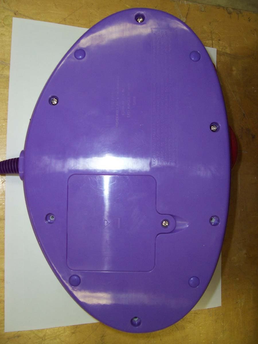
Click to zoom
Application Details
- Equipment Class
- DTS - Digital Transmission System
- Date of Grant
- Mar 18, 2007
- Application Purpose
- Original Equipment
- Date of Application
- Mar 18, 2007
- Equipment Note
- STARSTATION ENTERTAINMENT SYSTEM
- Frequency Range
- 2401.00000000 - 2478.00000000
- Company
- Fisher-Price Inc.
- Country
- United States
Documents & Files
Document Text
Text extracted from the exhibit documents filed with the FCC. Open a document above to read the original.
Users Manual
1 L3182 Please keep this instruction sheet for future reference, as it contains important information. Requires four “A” (LR6) and six “AAA” (LR03) alkaline batteries (not included) for operation. An adult must install batteries and set-up this system for use. Tool required for battery installation: Phillips screwdriver (not included). TV not included. TV image quality may vary. 2 Battery Installation Base Unit • Locate the battery compartment on the bottom of the base unit. • Loosen the screw in the battery compartment door with a Phillips screwdriver. Remove the battery compartment door. • Insert four “AA” (LR6) alkaline batteries. • Replace the battery compartment door and tighten the screw with a Phillips screwdriver. Do not over-tighten. • When images on your TV screen appear grainy or lose color, it's time for an adult to change the batteries! Microphones • Locate the battery compartment on each microphone. • Loosen the screw in the battery compartment door with a Phillips screwdriver. Remove the battery compartment door. • Insert three “AAA” (LR03) alkaline batteries, into each microphone. • Replace the battery compartment door and tighten the screw with a Phillips screwdriver. Do not over-tighten. • It's time for an adult to change the batteries in the microphone when: - Power light on microphone becomes dim. - Sounds from the microphone become faint or stop. • Protect the environment by not disposing of this product with household waste (2002/96/EC). Check your local authority for recycling advice and facilities (Europe only). 1.5V x 4 “AA” (LR6) Hint: We recommend using alkaline batteries for longer battery life. 1.5V x 3 “AAA” (LR03) 3 Battery Safety Information In exceptional circumstances, batteries may leak fl uids that can cause a chemical burn injury or ruin your product. To avoid battery leakage: • Do not mix old and new batteries or batteries of different types: alkaline, standard (carbon-zinc) or rechargeable (nickel-cadmium). • Insert batteries as indicated inside the battery compartment. • Remove batteries during long periods of non-use. Always remove exhausted batteries from the product. Dispose of batteries safely. Do not dispose of the product in a fi re. The batteries inside may explode or leak. • Never short-circuit the battery terminals. • Use only batteries of the same or equivalent type, as recommended. • Do not charge non-rechargeable batteries. • Remove rechargeable batteries from the product before charging. • If removable, rechargeable batteries are used, they are only to be charged under adult supervision. FCC Statement (United States Only) This equipment has been tested and found to comply with the limits for a Class B digital device, pursuant to Part 15 of the FCC Rules. These limits are designed to provide reasonable protection against harmful interference in a residential installation. This equipment generates, uses and can radiate radio frequency energy and, if not installed and used in accordance with the instructions, may cause harmful interfer- ence to radio communications. However, there is no guarantee that interference will not occur in a particular installation. If this equipment does cause harmful interference to radio or television reception, which can be determined by turning the equipment off and on, the user is encouraged to try to correct the interference by one or more of the following measures: • Reorient or relocate the receiving antenna. • Increase the separation between the equipment and receiver. • Consult the dealer or an experienced radio/TV technician for help. Note: Changes or modifi cations not expressly approved by the manufacturer responsible for compliance could void the user's authority to operate the equipment. StarStation ® Entertainment System Model Number: L3182 This device complies with Part 15 of the FCC Rules. Operation is subject to the following two conditions: (1) This device may not cause harmful interference and (2) this device must accept any interference received, including interference that may cause undesired operation. Consumer Relations Department, 636 Girard Avenue, East Aurora, New York 14052 4 Connecting Your Star Station ® to Your TV or VCR Important! Your TV or VCR must have audio and video input jacks. Camera Two Microphones ROM Cartridge Power/Volume Track Forward/Back Play/Pause Reset Button 5 • Position Star Station ® near your TV (or VCR) or on the fl oor in front of your TV. Important! Do not place Star Station ® on top of your TV. Keep excess cable off the fl oor and out of the way. • Make sure the power/volume dial on Star Station ® is off. The power light should be off. • Turn your TV or VCR off. Power/Volume Dial Power Light 2 • Locate the audio/video cable on the back of Star Station ® . • Plug the audio/video pins into the matching colored input jacks on your TV or VCR (Yellow for VIDEO IN, White for LEFT AUDIO IN and Red for RIGHT AUDIO IN). Note: We've included a detailed illustration to show how to connect Star Station ® to a TV or TV and VCR. Please refer to page 11. 3 Note: The photo above shows a combination T V/VCR/DVD with input jacks on t he front. Y our TV or V CR may ha ve input jacks on the back. 1 6 • Rotate the power/volume dial to turn power on. The power light turns on. • Turn your TV or VCR on. Power/Volume Dial 5 • To fi nd the picture transmitted on your TV screen, set your TV's or VCR's mode selector to INPUT or VIDEO IN. • Have your child stand about 4 or 5 feet (1,2m - 1,5 m) from Star Station ® . • Move the lens up or down until your child is visible on the TV screen. 6 • Insert the ROM cartridge into the slot in Star Station ® . Note: For proper function, turn the Star Station ® off before inserting ROM cartridges. 4 4 to 5 Feet (1,2m - 1,5 m) 7 No Image? If you do not see an image on your TV screen transmitted from Star Station ® , try the following: 1. Verify that your audio and video cable is fully inserted into your TV or VCR. 2. Press the channel down button …
Text truncated - open the document above for the full version.
Parts List/Tune Up Info
Bill of Materials TITLE LP Radio Module PMU BOM PCA # 121-27404 Revision ** SCH # REF-13314 Revision *B DATE 3/7/2005 Item Qt y CY Part Number Reference Description Manufacturer Mfr Part Number 1 1 NA ANT1 2.5GHZ H-STUB WIGGLE ANTENNA FOR 32MIL PCB NA NA 21 730-10012 C1 CAP 15PF 50V CERAMIC NPO 0402 Panasonic ECJ-0EC1H150J 3 1 730-11955 C3 CAP 2.0 PF 50V CERAMIC NPO 0402 Kemet C0402C209C5GACTU 4 1 730-11398 C4 CAP 1.5PF 50V CERAMIC NPO 0402 SMD PANASONIC ECJ-0EC1H1R5C 5 1 730-13322 C5 CAP 0.47 uF 50V CERAMIC X5R 0402 Murata GRM155R60J474KE19D 6 2 730-13037 C12,C7 CAP CERAMIC 10UF 6.3V X5R 0805 Kemet C0805C106K9PACTU 7 1 730-13400 C8 CAP 1 uF 6.3V CERAMIC X5R 0402 Panasonic ECJ-0EB0J105M 8 6 730-13404 C9,C10,C11,C13,C15,C16 CAP 0.047 uF 50V CERAMIC X5R 0402 AVX 0402YD473KAT2A 9 1 730-11952 C17 CAP 0.1 uF 50V CERAMIC X5R 0402 Kemet C0402C104K8PACTU 10 1 800-13317 D1 DIODE SCHOTTKY 0.5A 40V SOT23 DIODES INC BAT400D-7-F 11 1 420-11054 J1 CONN HDR VERT 10POS .100 GOLD Molex/GC/Waldom Inc. 10-89-1101 12 1 800-13401 L1 INDUCTOR 22NH 2% FIXED 0603 SMD Panasonic - ECG ELJ-RE22NGF2 13 1 800-11651 L2 INDUCTOR 1.8NH +-.3NH FIXED 0402 SMD Panasonic - ECG ELJ-RF1N8DF 14 1 800-10594 L3 COIL 10UH 1100MA CHOKE 0805 Newark 30K5421 15 1 630-11356 R1 RES 1.00 OHM 1/8W 1% 0805 SMD Yageo 9C08052A1R00FKHFT 16 1 610-13402 R2 RES 47 OHM 1/16W 5% 0402 SMD Panasonic - ECG ERJ-2GEJ470X 17 1 CYRF6936-40LFC U1 IC, LP 2.4 GHz RADIO SoC QFN-40 Cypress Semiconductor CYRF6936 Rev A5 18 1 800-13259 Y1 CRYSTAL 12.00MHZ HC49 SMD eCERRA GF-1200008 19 1 PDC-9274 *A PCB PRINTED CIRCUIT BOARD Cypress Semiconductor PDC-9274 *A 20 1 LABEL1 Serial Number XXXXXX 21 1 LABEL2 PCA # 121-27404 ** NO LOAD COMPONENTS - DO NOT INSTAL L 22 1 730-13403 C6 CAP 47UF 6.3V CERAMIC X5R 1210 Panasonic ECJ-4YB0J476M 23 1 630-10242 R1 RES CHIP 0.0 OHM 1/10W 5% 0805 SMD Phycomp USA Inc 9C08052A0R00JLHFT 24 1 730-13404 C7 CAP 0.047 uF 50V CERAMIC X5R 0402 AVX 0402YD473KAT2A Cypress Semiconductor Corporation • 3901 North First Street • San Jose • CA 95134 • 408-943-2600 Page 1 of 1
Test Report
Retlif Testing Laboratories, Test Report R-11824-2, Fisher Price Incorporated FCC ID: CCTL3182-07-B Page 1 of 55 Technical Information Applicant Manufacturer Name: Fisher Price Inc. Name: Fisher Price Inc. Address: 636 Girard Avenue Address: 636 Girard Avenue City, State, Zip: East Aurora, NY 14052 City, State, Zip: East Aurora, NY 14052 Test Specification: FCC Rules and Regulations Part 15, Subpart C, Para. 15.247 Test Procedure: ANSI C63.4:2003 Test Sample Description Test Sample: Wireless Microphone Base Unit Brandname: Star Performance Model Number: L3182 Type: 2.4 GHz Spread Spectrum Transceiver Power Requirements: 6.0 VDC derived from 4 fully charged AA Batteries Frequency of Operation: 2.401 to 2.478 GHz Tests Performed Para. 15.247(a)(2) 6 dB Bandwidth Para. 15.247(b) (3) Output Power Para. 15.247 (d) Transmitter Spurious Radiated Emissions, Restricted Bands Para. 15.247 (d) (e) Power Spectral Density Para. 15.109 (a) Digital Device Spurious Radiated Emissions Retlif Testing Laboratories, Test Report R-11824-2, Fisher Price Incorporated FCC ID: CCTL3182-07-B Page 2 of 55 Report of Measurements Applicant: Fisher Price Inc. Device: Wireless Microphone Base Unit FCC ID: CCTL3182-07-B Power Requirements: 6.0 VDC derived from fully charged 4 AA Batteries Applicable Rule Section: Part 15, Subpart C, Section 15.247 Test Results 15.247 (a) (2) The minimum 6 dB bandwidth measured 883 kHz and was no less than 500 kHz. 15.247 (b) (3) The device operates in the 2400 - 2483.5 MHz band. The maximum peak output power measured to be 0.31 mWatts and did not exceed 1 watt. 15.247 (b) (4) The system operating under the provisions of this section is operated in a manner that ensures that the public is not exposed to radio frequency energy levels in excess of the Commission’s guidelines. The maximum Output Power was measured to be 0.31 mWatts. 15.247 (d) In any 100 kHz bandwidth outside the frequency band in which the Spread spectrum intentional radiator is operating, the radio frequency power that is produced by the intentional radiator is at least 20 dB below that in the 100 kHz bandwidth within the band that contains the highest level of the desired power. All emissions, which fell within the restricted bands specified in 15.205(a), were measured and found to be in compliance with the limits specified in 15.209(a). 15.247 (d) (e) The maximum power spectral density measured to be -19.3 dBm and does not exceed 8 dBm in any 3 kHz band. 15.109 (a) The field strength of spurious radiated emissions did not exceed the class B limits specified. Retlif Testing Laboratories, Test Report R-11824-2, Fisher Price Incorporated FCC ID: CCTL3182-07-B Page 3 of 55 Spectrum Analyzer Desensitization Considerations Due to the nature of the emissions being measured, care was taken to ensure that the resolution bandwidth of the spectrum analyzer was adequate to provide accurate measurements. FCC specified bandwidths of 100 kHz and 1 MHz were utilized below and above 1 GHz, respectively. General Notes 1. All readings were taken utilizing a peak and/or average detector function at a test distance of 3 meters. 2. All measurements were made with fully charged Batteries. 3. The frequency range was scanned from 30 MHz to 25 GHz. All emissions not reported were more than 20 dB below the specified limit. 4. For transmitter testing, the device was operated at the following frequencies: Low Band Middle Band Upper Band 2.401 GHz 2.439 GHz 2.478 GHz The device incorporates two radio transmitters (A and B). Each transmitter was tested individually. Note: due to the nature of the design, the radios cannot operate together; they must operate one at a time. 5. For digital device testing, device was powered on without the transmitter operating. 6. The device was tested with the following external accessories: Panasonic VCR 1.9 meter audio cable Modifications The following modifications were made to the EUT during the course of this testing program in order to ensure compliance: • Two wide band ferrite bead inductors, L4 and L5 were added to the 27 MHz oscillator circuit in the imager section. Part number: BLM41AF151SN1 Manufactured by Murata Manufacturing Co., LTD. Retlif Testing Laboratories, Test Report R-11824-2, Fisher Price Incorporated FCC ID: CCTL3182-07-B Page 5 of 55 Equipment List FCC Part 15, Subpart B, Spurious Case Radiated Emissions, 15.247(d) EN Type Manufacturer Description Model No. Cal Date Due Date 067 Open Area Test Site Retlif 3 Meter RNY 9/12/2006 9/12/2009 133 Broadband Pre-Amplifier Electro-Metrics 10 kHz - 1 GHz, 26dB BPA-1000 6/27/2006 6/27/2007 141 Spectrum Analyzer Hewlett Packard 100 Hz - 40 GHz 8566B 10/10/2006 4/10/2007 141B Quasi-Peak Adaptor Hewlett Packard 100 Hz - 1 GHz 85650A 10/9/2006 4/9/2007 206B 6.0 dB Attenuator Texscan 0 - 1.0 GHz FP-50 - 6 dB 6/27/2006 6/27/2007 224 Shielded Enc. (24x20x12) Universal Shielding 100dB, 14kHz - 10GHz 1 3/31/2006 3/31/2007 224B Shielded Enc. (8x8x12) Universal Shielding 100dB, 14kHz - 10GHz 1B 3/31/2006 3/31/2007 512 Graphics Plotter Hewlett Packard N/A 7470A 10/18/2006 10/18/2007 523 Biconilog Electro-Mechanics 26 - 2000 MHz 3142B 11/10/2006 11/10/2007 617 Interference Analyzer Electro-Metrics 10 kHz - 1 GHz EMC-30 2/21/2006 3/21/2007 712 EMI Test Receiver Rohde & Schwarz 20 Hz - 26.5 GHz ESI26 9/26/2006 9/26/2007 712A Cable Retlif 10 kHz - 18 GHz R&S Analyzer 6/3/2006 6/3/2007 712B Cable Retlif 10 kHz - 18 GHz R&S Analyzer 8/21/2006 8/21/2007 712C Cable Retlif 10 kHz - 18 GHz R&S Analyzer 6/3/2006 6/3/2007 767 Biconilog EMCO 26 - 2000 MHz 3142B 10/12/2006 10/12/2007 Occupied Bandwidth, Spurious Case Radiated Emissions, Power Output, Power Spectral Density EN Type Manufacturer Description Model No. Cal Date Due Date 067 Open Area Test Site Retlif 3 Meter RNY 9/12/2006 9/12/2009 128 Double Ridged Guide Electro-Mechanics 1 GHz - 18 GHz 3105 3/27/2006 3/27/2007 129E High Gain Horn Antenna Microlab/FXR 18 GHz - 26.5 GHz K638A 9/20/2006 9/20/2007 133 Broadband Pre-Amp…
Text truncated - open the document above for the full version.
Contact Information
Applicant
Jerry Miller(Quality Staff Engineer)
Test Firm
Retlif Testing LaboratoriesMichael Bozza
Technical Specifications
| # | Rule Parts | Frequency Range | Power Output |
|---|---|---|---|
| 1 | 15C | 2.40 GHz - 2.48 GHz | 300.00 µW |
Other Applications from Fisher-Price Inc.

CCT-DNV31-15
Sep 29, 2015Smart Toy Bear (DNV31), Smart Toy Panda (DNV30), Smart Toy Monkey (DNV32)
Equipment Class
DXX - Part 15 Low Power Communication Device Transmitter
CCT-CBV76-14
Jun 22, 2014Mattel Bluetooth Low Energy Module
Equipment Class
DTS - Digital Transmission System
CCTT4841T-10
Jul 27, 2010Digital Audio Monitor (Baby Unit)
Equipment Class
DSS - Part 15 Spread Spectrum Transmitter
CCTT4256T-10
Jul 22, 2010Digital Video Monitor (Baby Unit)
Equipment Class
DSS - Part 15 Spread Spectrum Transmitter
CCTT4256R-10
Jul 21, 2010Digital Video Monitor (Parent Unit)
Equipment Class
DSS - Part 15 Spread Spectrum Transmitter