CCTN932609T2.4GHz FHSS Baby Unit with Camera
Fisher-Price Inc.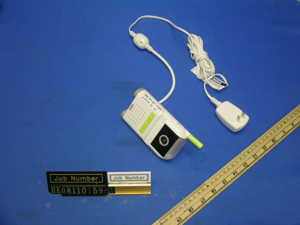
Click to zoom
Application Details
- Equipment Class
- DSS - Part 15 Spread Spectrum Transmitter
- Date of Grant
- Feb 16, 2009
- Application Purpose
- Original Equipment
- Date of Application
- Feb 16, 2009
- Equipment Note
- 2.4GHz FHSS Baby Unit with Camera
- Frequency Range
- 2404.35000000 - 2471.94000000
- Company
- Fisher-Price Inc.
- Country
- United States
Documents & Files
Document Text
Text extracted from the exhibit documents filed with the FCC. Open a document above to read the original.
Users Manual
N9326N9326 www.fi sher-price.comwww.fi sher-price.com 2 Important! To prevent electric shock, do not immerse in water; wipe clean with damp cloth. DANGER To prevent strangulation with power cord, never place transmitter within reach of child. WARNING This product cannot replace responsible adult supervision. CAUTION 3 • For proper setup and use, please read these instructions. • Please keep this instruction sheet for future reference, as it contains important information. • Transmitter operates on AC current. Receiver operates on AC current (use enclosed AC adaptor) or 3.6V NiMH rechargeable battery pack (included). • Before fi rst time use, charge the rechargeable battery pack for four hours. • Adult assembly is required for wall mounting. Tools needed for assembly: electric drill, ¼" drill bit, hammer, Phillips screwdriver (tools not included). • This product is not intended to be used as a medical monitor and its use should not replace adult supervision. • Test sound/audio reception of receiver before fi rst-time use and whenever you change location of the transmitter. • Adults Note: Periodically examine this product for damage to the cord, housing or other parts that may result in the risk of fi re, electric shock or injury. If the product is damaged, do not use it. • Never use extension cords with the AC adaptor. • Never use transmitter or receiver near water (i.e. bathtub, sink, wet basement, etc.). • Always use transmitter and receiver where there is adequate ventilation. To prevent overheating, keep away from heat sources such as radiators, heat registers, direct sunlight, stoves, amplifi ers, fi re, excessive heat or other appliances that produce heat. • Fisher-Price ® does not recommend the use of two monitors in one house. • Always remember that you are using public airwaves when using your monitor. Conversations, even from rooms near your transmitter, may broadcast to other nursery monitors, radios, cordless telephones or scanners outside your home. To protect the privacy of your home, always turn off the transmitter when not in use. • Do not connect to more than the recommended number of power supplies. • The AC adaptor is not a toy. • Disconnect the AC adaptor from the receiver before cleaning. • If this product begins to operate erratically, you may need to reset the electronics. Turn the transmitter power/volume dial off and then back on; press the receiver main power/menu button to turn power off and press again to turn power back on. • Carrier Frequency: 2.4 Ghz • Product features and decoration may vary from photos. Important! 4 9 10 12 11 4 14 Features ReceiverTransmitter 6 1 4 7 3 13 2 5 8 AC Adaptor/Charger Transmitter Tabletop Stand 5 1 Main Power/Menu Button – Press to turn receiver main power ON; press again for the main menu; press and hold for approximately fi ve seconds to turn main power OFF. 2 Power L.E.D. – Turns on when receiver power is ON. 3 Menu Navigation/Volume Control Button – Press up, down or side arrows to scroll through menu options. When the menu is not on the screen, press the side arrows to adjust volume. 4 Speaker 5 Video Screen 6 Video Screen On/Off Button – Press to turn the video screen on; press again to turn it off. 7 Sound Lights – Shows you baby's sounds. 8 DC Input Jack – Insert the AC adaptor/charger pin to use AC power/charge the battery. 9 Camera Lens 10 Power/Volume Dial – Rotate to turn transmitter power ON and adjust volume to a comfortable level for baby. 11 Microphone 12 Music, Sounds and Night Light Buttons Music – Choose from 5 lullaby songs. Sounds – Play nature sounds. Night Light – Turn on night light for baby. 13 Power L.E.D. – Turns on when transmitter power is ON. 14 Night Light – Lights room with a soft glow. Features 6 Fasteners Shown Actual Size Wall Mount Parts Wall Mount BracketCord WrapBase Stand Wall Anchor – 4 #8 x 2" Screw – 4 7 Charging the Battery (Inside the Receiver) DC Input Jack IMPORTANT! Fully charge the receiver (with battery pack inside) for four hours before fi rst-time use. Use only the included AC adaptor charger! Do not use any other adaptor charger. • Fit the AC adaptor charger pin into the DC input jack on the receiver. • Plug the AC adaptor charger into a standard wall outlet. Notes: If power fl ow to the wall outlet is controlled by a switch, make sure the switch is “ON”. Use the AC adaptor charger only in a wall outlet. Do not plug the AC adaptor charger into a ceiling outlet. To connect to a supply that is not in the United States, use an adaptor (not included and sold separately) with the proper confi guration for the power outlet. • If you are monitoring baby while charging the battery pack, you will see the charging icon on the video screen. 8 Testing Sound/Video Reception • Place the transmitter in the room where you intend to use it. • Point the transmitter toward the area you will be monitoring. Adjust the camera angle by rotating the top portion of the transmitter up or down. • Turn the power/volume dial ON. • Turn on a radio. Power Dial Test transmitter transmission and receiver reception before installing the wall mount bracket and cord wrap (if used) and each time you change location of use. Radio 9 Testing Sound/Video Reception • Place the receiver in the room where you intend to use it. • Press the main power/menu select button on the front of the receiver to turn power ON. • Adjust the receiver location for best reception. • When sound is picked up by the receiver, the sound lights will turn on. - One or two lights indicate quieter sounds. - Three or more lights indicate louder sounds. • If you cannot see an image on the receiver screen, adjust the transmitter location or camera angle. Sound Lights Main Power/Menu Select Button 10 Transmitter Wall Mount Installation To prevent strangulation with power cord, never place transmitter within reach of child. WARNING IMPORTANT! Test the reception of the monitor before installing the wall mount bracket and cord wrap. Use the assistanc…
Text truncated - open the document above for the full version.
External Photos
INTERTEK TESTING SERVICES External Photos FCC ID: CCTN932609T external photos - 1 of 1
Internal Photos
INTERTEK TESTING SERVICES Internal photos FCC ID: CCTN932609T internal photos - 1 of 5 Internal Photo - 1 Internal Photo - 2 INTERTEK TESTING SERVICES Internal photos FCC ID: CCTN932609T internal photos - 2 of 5 Internal Photo - 3 Internal Photo - 4 INTERTEK TESTING SERVICES Internal photos FCC ID: CCTN932609T internal photos - 3 of 5 Internal Photo - 5 Internal Photo - 6 INTERTEK TESTING SERVICES Internal photos FCC ID: CCTN932609T internal photos - 4 of 5 Internal Photo - 7 Internal Photo - 8 INTERTEK TESTING SERVICES Internal photos FCC ID: CCTN932609T internal photos - 5 of 5 Internal Photo - 9 Internal Photo - 10
RF Exposure Info
INTERTEK TESTING SERVICES FCC ID: CCTN932609T RF exposure - 1 of 1 For Maximum Permissible Exposure (MPE) evaluation of the camera unit, the maximum power density at 20 cm from this mobile transmitter shall be less than the General Population / Uncontrolled MPE limit in OET Bulletin 65. For the camera unit of tested model of N9326, the maximum field strength measured (FS) was 117.0 dBμV/m. The distance (D) between the antenna and the equipment under test (EUT) was 3 meters. And the maximum source-based time-averaging duty factor is 76.6%. From these data, the exposed power density at a distance (R) of 20cm from the center of radiation of the antenna can be calculated according to OET Bulletin 65 as follow: The radiated power = (FS*D) 2 / 30 = 150.36 mW The radiated (EIRP) source-based time-averaging output power = (150.36 * 0.766) mW = 115.17 mW The power density at 20 cm from the antenna = EIRP / 4πR 2 = 0.0229 mW cm -2 In the frequency range of 1,500 - 100,000MHz, the MPE limit is 1.0 mWcm -2 for general population and uncontrolled exposure. As the measured power density at 20cm from the transmitter is lower than the MPE limit, the compliance to the MPE limit can be ensured by indicating the minimum 20cm separation between the transmitter's radiating structures and body of the user or nearby persons. The following RF exposure statement is proposed to be included in the user manual: “ FCC RF Radiation Exposure Statement Caution: To maintain compliance with the FCC’s RF exposure guidelines, place the camera unit at least 20cm from nearby persons.”
Test Report
- The test report only allows to be revised within the retention period unless further standard or the requirement was noticed. - This report is for the exclusive use of Intertek's Client and is provided pursuant to the agreement between Intertek and its Client. Intertek's responsibility and liability are limited to the terms and conditions of the agreement. Intertek assumes no liability to any party, other than to the Client in accordance with the agreement, for any loss, expense or damage occasioned by the use of this report. Only the Client is authorized to permit copying or distribution of this report and then only in its entirety. Any use of the Intertek name or one of its marks for the sale or advertisement of the tested material, product or service must first be approved in writing by Intertek. The observations and test results in this report are relevant only to the sample tested. This report by itself does not imply that the material, product, or service is or has ever been under an Intertek certification program. Intertek Testing Services Hong Kong Ltd. 2/F., Garment Centre, 576 Castle Peak Road, Kowloon, Hong Kong. Tel: (852) 2173 8888 Fax: (852) 2785 5487 Website: www.hk.intertek-etlsemko.com Fisher-Price Inc. Application For Certification 2.4GHz Frequency Hopping Spread Spectrum Baby Unit with Camera (FCC ID: CCTN932609T) HK08110159-1 KS/ ac December 23, 2008 INTERTEK TESTING SERVICES Test Report Number: HK08110159-1 FCC ID: CCTN932609T Page 1 of 31 MEASUREMENT/TECHNICAL REPORT Fisher-Price Inc. – MODEL: N9326 FCC ID: CCTN932609T This report concerns (check one) Original Grant X Class II Change Equipment Type: DSS-Part 15 Spread Spectrum Transmitter Deferred grant requested per 47 CFR 0.457(d)(1)(ii)? Yes No X If yes, defer until : date Company Name agrees to notify the Commission by: date of the intended date of announcement of the product so that the grant can be issued on that date. Transition Rules Request per 15.37? Yes No X If no, assumed Part 15, Subpart C for intentional radiator - the new 47 CFR [10-01-07 Edition] provision. Report prepared by: Sit Kim Wai, Ken Intertek Testing Services Hong Kong Ltd. 2/F., Garment Centre, 576 Castle Peak Road, Kowloon, Hong Kong. Phone: 852-2173-8538 Fax: 852-2741-1693 INTERTEK TESTING SERVICES Test Report Number: HK08110159-1 FCC ID: CCTN932609T Page 2 of 31 Table of Contents 1.0 Summary of Test................................................................................................. 4 2.0 General Description............................................................................................ 6 2.1 Product Description .......................................................................................... 6 2.2 Related Submittal(s) Grants.............................................................................. 6 2.3 Test Methodology............................................................................................. 7 2.4 Test Facility ...................................................................................................... 7 3.0 System Test Configuration................................................................................. 9 3.1 Justification ...................................................................................................... 9 3.2 EUT Exercising Software.................................................................................. 9 3.3 Special Accessories ....................................................................................... 10 3.4 Measurement Uncertainty............................................................................... 10 3.5 Equipment Modification .................................................................................. 10 4.0 Measurement Results....................................................................................... 12 4.1 Maximum Conducted Output Power at Antenna Terminals ............................. 12 4.2 Maximum 20 dB RF Bandwidth ...................................................................... 13 4.3 Minimum Number of Hopping Frequencies ..................................................... 14 4.4 Minimum Hopping Channel Carrier Frequency Separation.............................. 15 4.5 Average Channel Occupancy Time ................................................................ 16 4.6 Out of Band Conducted Emission ................................................................... 17 4.7 Transmitter Radiated Emissions in Restricted Bands ...................................... 18 4.8 Spurious Emissions from Transmitter ............................................................. 19 4.9 Field Strength Calculation............................................................................... 20 4.10 Radiated Emission Configuration Photograph – Baby Unit .............................. 21 4.11 Radiated Emission Data – Baby Unit .............................................................. 22 4.12 AC Line Conducted Emission ......................................................................... 27 4.13 AC Line Conducted Configuration Photograph – Baby Unit............................. 28 4.14 AC Line Conducted Emission Data – Baby Unit .............................................. 29 4.15 Transmitter Duty Cycle Calculation and Measurement .................................... 30 4.16 Radio Frequency Radiation Exposure............................................................. 31 Appendix - Exhibits of Application for Certificate INTERTEK TESTING SERVICES Test Report Number: HK08110159-1 FCC ID: CCTN932609T Page 3 of 31 EXHIBIT 1 SUMMARY OF TEST RESULTS INTERTEK TESTING SERVICES Test Report Number: HK08110159-1 FCC ID: CCTN932609T Page 4 of 31 1.0 Summary of Test Fisher-Price Inc. - MODEL: N9326 FCC ID: CCTN932609T TEST REFERENCE RESULTS Max. Output Power 15.247(b)(1) Pass Min. No. of Hopping Frequencies 15.247(a)(1) Pass Min. Hopping Channel Carrier Frequency Separation 15.247(a)(1)…
Text truncated - open the document above for the full version.
Test Report
INTERTEK TESTING SERVICES Minimum Hopping Channel Carrier Frequency Separation Plots FCC ID: CCTN932609T fsepa - 1 of 1 A0 Plot B4
Test Report
Report No.: HK08110159-1 Tx Mode (Baby Unit) AC Mains “L” Ctrl No.: N/A PAGE 1 Scan Settings (1 Range) |--------- Frequencies -----------||----------- Receiver Settings ------------| Start Stop Step IF BW Detector M-Time Atten Preamp OpRge 150k 30M 4.5k 10k PK+AV 10ms AUTO LN OFF 60dB Final Measurement: x QP / + AV Meas Time: 1 s Subranges: 16 Acc Margin: 20dB Transducer No. Start Stop Name 2 1 9k 30M EW0700 3 9k 30M EW2454 12 9k 30M EW0090 0 10 20 30 40 50 60 70 80 90 dBuV 100 0.15 MHz 30 1 10 F15Q F15A Report No.: HK08110159-1 Tx Mode (Baby Unit) AC Mains “L” Ctrl No.: N/A Scan Settings (1 Range) |--------- Frequencies -----------||----------- Receiver Settings ------------| Start S top Step IF BW De te ctor M-Time Atten P rea mp OpRge 15 0k 3 0M 4.5 k 1 0k P K+AV 10ms AUTO LN O FF 60 dB Final Measurement Results: Fr equency Q P Lev el QP Li mi t Delta MHz dBuV dBuV dB 0 .18 150 44 .6 6 4.4 -19. 8 0 .27 600 42 .4 6 0.9 -18. 5 0 .30 750 51 .0 6 0.0 -9.0 0 .55 050 49 .6 5 6.0 -6.4 0 .61 350 50 .1 5 6.0 -5.9 0 .97 800 48 .9 5 6.0 -7.1 1 .43 700 42 .2 5 6.0 -13. 8 1 .59 000 48 .8 5 6.0 -7.2 2 .57 100 44 .8 5 6.0 -11. 2 3 .30 000 43 .2 5 6.0 -12. 8 4 .22 250 39 .7 5 6.0 -16. 3 6 .29 700 33 .6 6 0.0 -26. 4 Fr equency A V Le vel A V Lim it D elt a MHz dBuV dBuV dB 0 .30 300 37 .3 5 0.1 -12. 8 0 .55 050 36 .8 4 6.0 -9.2 0 .60 900 36 .6 4 6.0 -9.4 0 .91 500 34 .2 4 6.0 -11. 8 1 .46 850 35 .0 4 6.0 -11. 0 1 .71 150 42 .3 4 6.0 -3.7 2 .26 050 31 .2 4 6.0 -14. 8 3 .06 150 30 .2 4 6.0 -15. 8 4 .15 950 25 .5 4 6.0 -20. 5 * limit e xce eded Report No.: HK08110159-1 Tx Mode (Baby Unit) AC Mains “N” Ctrl No.: N/A PAGE 1 Scan Settings (1 Range) |--------- Frequencies -----------||----------- Receiver Settings ------------| Start Stop Step IF BW Detector M-Time Atten Preamp OpRge 150k 30M 4.5k 10k PK+AV 10ms AUTO LN OFF 60dB Final Measurement: x QP / + AV Meas Time: 1 s Subranges: 16 Acc Margin: 20dB Transducer No. Start Stop Name 2 1 9k 30M EW0700 3 9k 30M EW2454 12 9k 30M EW0090 0 10 20 30 40 50 60 70 80 90 dBuV 100 0.15 MHz 30 1 10 F15Q F15A Report No.: HK08110159-1 Tx Mode (Baby Unit) AC Mains “N” Ctrl No.: N/A Sca n Setti ngs (1 Range) |--------- Frequencies -----------||----------- Receiver Settings ------------| Start Stop S te p I F BW Detec tor M-Time Atte n Prea mp OpRge 15 0k 30 M 4 .5k 10 k PK+AV 1 0ms AUTO LN OFF 60 dB Final Measurement Results: Fre que ncy QP Le ve l QP Limit De lta MHz dBuV dBuV dB 0. 181 50 42.9 64 .4 -21 .5 0. 244 50 48.2 62 .0 -13 .8 0. 303 00 49.7 60 .1 -10 .4 0. 429 00 47.7 57 .3 -9. 6 0. 672 00 49.4 56 .0 -6. 6 0. 982 50 47.7 56 .0 -8. 3 1. 405 50 48.0 56 .0 -8. 0 1. 531 50 49.1 56 .0 -6. 9 2. 575 50 45.4 56 .0 -10 .6 3. 493 50 43.5 56 .0 -12 .5 4. 164 00 41.8 56 .0 -14 .2 5. 887 50 36.3 60 .0 -23 .7 Fre que ncy AV Le vel AV Limit De lta MHz dBuV dBuV dB 0. 244 50 39.6 52 .0 -12 .4 0. 366 00 41.7 48 .6 -6. 9 0. 429 00 37.9 47 .3 -9. 4 0. 672 00 39.3 46 .0 -6. 7 0. 978 00 38.2 46 .0 -7. 8 1. 284 00 36.0 46 .0 -10 .0 1. 774 50 38.9 46 .0 -7. 1 2. 143 50 34.8 46 .0 -11 .2 3. 183 00 31.0 46 .0 -15 .0 4. 407 00 27.9 46 .0 -18 .1 * l imit ex cee ded
Test Report
INTERTEK TESTING SERVICES Transmitter Duty Cycle Calculation and Measurement Plots FCC ID: CCTN932609T dcc - 1 of 1 Plot B7
Contact Information
Applicant
Jerry Miller(Quality Staff Engineer)
Technical Contact
Intertek Testing Services Hong Kong LtdKen Sit
[email protected]85221738888
Flat D, 5/F, Garment Centre · Kowloon · Hong Kong
Non-Technical Contact
Intertek Testing Services Hong Kong LtdKen Sit
[email protected]85221738888
Test Firm
Intertek Testing Services Hong Kong Ltd.Billy Chow
Technical Specifications
| # | Rule Parts | Frequency Range | Power Output |
|---|---|---|---|
| 1 | 15C | 2.40 GHz - 2.47 GHz | 45.19 mW |
Other Applications from Fisher-Price Inc.

CCT-DNV31-15
Sep 29, 2015Smart Toy Bear (DNV31), Smart Toy Panda (DNV30), Smart Toy Monkey (DNV32)
Equipment Class
DXX - Part 15 Low Power Communication Device Transmitter
CCT-CBV76-14
Jun 22, 2014Mattel Bluetooth Low Energy Module
Equipment Class
DTS - Digital Transmission System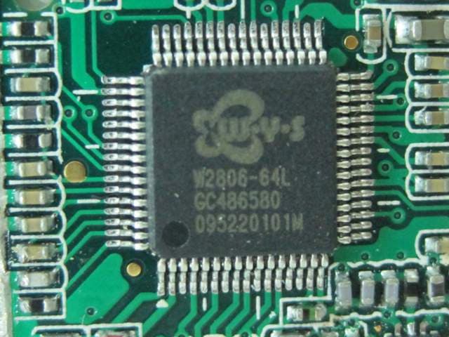
CCTT4841T-10
Jul 27, 2010Digital Audio Monitor (Baby Unit)
Equipment Class
DSS - Part 15 Spread Spectrum Transmitter
CCTT4256T-10
Jul 22, 2010Digital Video Monitor (Baby Unit)
Equipment Class
DSS - Part 15 Spread Spectrum Transmitter
CCTT4256R-10
Jul 21, 2010Digital Video Monitor (Parent Unit)
Equipment Class
DSS - Part 15 Spread Spectrum Transmitter