CCTT4839-10900MHz Transmitter - Baby Unit
Fisher-Price Inc.
Click to zoom
Application Details
- Equipment Class
- DXX - Part 15 Low Power Communication Device Transmitter
- Date of Grant
- Jun 27, 2010
- Application Purpose
- Original Equipment
- Date of Application
- Jun 27, 2010
- Equipment Note
- 900MHz Transmitter - Baby Unit
- Frequency Range
- 905.25000000 - 906.75000000
- Company
- Fisher-Price Inc.
- Country
- United States
Documents & Files
Document Text
Text extracted from the exhibit documents filed with the FCC. Open a document above to read the original.
Users Manual
23 T4839 www.fi sher-price.com IMPORTANT! To prevent strangulation with power cord, never place transmitter within reach of child. WARNING This product cannot replace responsible adult supervision. CAUTION DANGER To prevent electric shock, do not immerse in water; wipe clean with damp cloth. • For proper setup and use, please read these instructions. • Please keep this instruction sheet for future reference, as it contains important information. • Transmitter operates on AC current (use enclosed AC adaptor) or DC current (four “AAA” batteries, included). • Receiver operates on AC current (use enclosed AC adaptor) or DC current (three “AAA” LR03 alkaline batteries, not included). Note: A plastic tab is attached to the transmitter for in-store demonstration purposes. While the tab may have already been removed, check the transmitter to be sure. If the plastic tab is still attached, pull and remove the tab from the transmitter. Throw the plastic tab away. • Adult setup is required. • Tool needed for battery installation: Phillips screwdriver (not included). • This product is not intended to be used as a medical monitor and its use should not replace adult supervision. • Test sound reception of receiver before fi rst-time use and whenever you change location of the transmitter. • To prevent entanglement: - Never place transmitter in a crib or playpen. Keep transmitter and receiver out of baby’s reach. - Never use extension cords with the AC adaptors. • Adults Note: Periodically examine the AC adaptors for damage to the cord, housing or other parts that may result in the risk of fi re, electric shock or injury. If an AC adaptor is damaged, do not use it. • Never use transmitter or receiver near water (i.e. bathtub, sink, wet basement, etc.). • Always use the transmitter and receiver where there is adequate ventilation. To prevent overheating, keep the transmitter and receiver away from heat sources such as radiators, heat registers, direct sunlight, fi re, stoves amplifi ers, or other appliances which produce heat. • Do not connect the transmitter or the receiver (if AC adaptor is used) to more than the recommended number of power supplies. • An AC adaptor is not a toy. • Disconnect the AC adaptor from the transmitter and receiver before cleaning. • Fisher-Price ® does not recommend the use of two monitors in one house. • Always remember that you are using public airwaves when using your monitor. Conversations, even from rooms near your transmitter, may broadcast to other nursery monitors, radios, cordless telephones or scanners outside your home. To protect the privacy of your home, always turn off the transmitter when not in use. • Carrier Frequency - 900 MHz • Product features and decoration may vary from photographs. IMPORTANT! Fisher Price, Inc., a subsidiary of Mattel, Inc., East Aurora, NY 14052 U.S.A. ©2010 Mattel, Inc. All Rights Reserved. ® and ™ designate U.S. trademarks of Mattel, Inc. PRINTED IN CHINA T4839pr-0920 5678 1 2 3 4 Transmitter Features 1 Nightlight Button – Press to turn on a soft glow. 2 Nightlights 3 Power Button and L.E.D. 4 Microphone 5 Nightlight Timer Switch - Turn on for 30 minutes of light. 6 Channel Switch - Choose from four different channels. 7 Power/Volume Dial 8 Power L.E.D. and Range Indicator - Lights when receiver power is ON; fl ashes (and you’ll hear a tone too) when the receiver is out of range of transmitter. 9 Sound Lights – Watch these lights to see baby’s sounds. 10 Start/Stop Button - Press the button to start the nap timer; press the button again to stop the nap timer. Press and hold the button to set the clock time. 11 Reset Button - Press and hold the button to reset the nap timer. Use this button in clock set mode to make selections. 12 LCD Screen 13 Channel Switch - Choose from four different channels. 14 Clip - (backside of receiver) - Fasten to your clothes to stay in touch with baby around the house or yard. • Locate the battery compartment door on the back of each receiver. • Loosen the screw in each battery compartment door with a Phillips screwdriver. Remove each battery compartment door. • Insert three “AAA” (LR03) alkaline batteries into each battery compartment. • Replace each battery compartment door. Tighten the screw with a Phillips screwdriver. Do not over-tighten. For best performance, we recommend replacing the batteries that came with the transmitter with four, new “AAA” (LR03) alkaline batteries. • Locate the battery compartment door on the bottom of the transmitter. • Loosen the screws in the battery compartment door. Remove the door. • Insert four “AAA” (LR03) alkaline batteries into the battery compartment. • Replace the battery compartment door and tighten the screws. Hint: You can also use the included AC adaptor to power the transmitter. Hint: We recommend using alkaline batteries for longer battery life. Receiver Battery Installation (Optional) In exceptional circumstances, batteries may leak fl uids that can cause a chemical burn injury or ruin your product. To avoid battery leakage: • Do not mix old and new batteries or batteries of different types: alkaline, standard (carbon-zinc) or rechargeable (nickel-cadmium). • Insert batteries as indicated inside the battery compartment. • Remove batteries during long periods of non-use. Always remove exhausted batteries from the product. Dispose of batteries safely. Do not dispose of this product in a fi re. The batteries inside may explode or leak. • Never short-circuit the battery terminals. • Use only batteries of the same or equivalent type, as recommended. • Do not charge non-rechargeable batteries. • Remove rechargeable batteries from the product before charging. • If removable, rechargeable batteries are used, they are only to be charged under adult supervision. Battery Safety Information 8 71011 12 Receiver FeaturesTransmitter Battery Replacement 14 9 1,5V x 3 “AAA” (LR03) 1,5V x 4 “AAA” (LR03) BACK VIEW SIDE VIEW 6 5 13 9101112 Test transmitter and receiver recept…
Text truncated - open the document above for the full version.
External Photos
INTERTEK TESTING SERVICES External Photos FCC ID: CCTT4839-10 IC: 4390A-T483910 external photos - 1 of 2 INTERTEK TESTING SERVICES External Photos FCC ID: CCTT4839-10 IC: 4390A-T483910 external photos - 2 of 2
Internal Photos
INTERTEK TESTING SERVICES Internal photos FCC ID: CCTT4839-10 IC: 4390A-T483910 internal photos - 1 of 4 Internal Photo - 1 Internal Photo - 2 INTERTEK TESTING SERVICES Internal photos FCC ID: CCTT4839-10 IC: 4390A-T483910 internal photos - 2 of 4 Internal Photo - 3 Internal Photo - 4 INTERTEK TESTING SERVICES Internal photos FCC ID: CCTT4839-10 IC: 4390A-T483910 internal photos - 3 of 4 Internal Photo - 5 Internal Photo - 6 INTERTEK TESTING SERVICES Internal photos FCC ID: CCTT4839-10 IC: 4390A-T483910 internal photos - 4 of 4 Internal Photo - 7
Test Report
INTERTEK TESTING SERVICES Radiated Emission on the Bandedge Plots FCC ID: CCTT4839-10 IC: 4390A-T483910 be - 1 of 1 Baby unit, Lowest channel Baby unit, Highest channel
Test Report
Report no.: HK10050490-1 Tx Mode with Light On AC Mains Ctrl No.: N/A 150 kHz30 MHz 1 PK CLRWR 2 AV CLRWR SGL TDS 6DB dBμV dBμV AC RBW 9 kHz MT 1 s PREAMP OFFAtt 10 dB AUTO 1 MHz10 MHz 0 10 20 30 40 50 60 70 80 90 100 CF15MAV CF15MQP Date: 11.MAY.2010 21:31:43
Test Report
- The test report only allows to be revised within the retention period unless further standard or the requirement was noticed. - This report is for the exclusive use of Intertek's Client and is provided pursuant to the agreement between Intertek and its Client. Intertek's responsibility and liability are limited to the terms and conditions of the agreement. Intertek assumes no liability to any party, other than to the Client in accordance with the agreement, for any loss, expense or damage occasioned by the use of this report. Only the Client is authorized to permit copying or distribution of this report and then only in its entirety. Any use of the Intertek name or one of its marks for the sale or advertisement of the tested material, product or service must first be approved in writing by Intertek. The observations and test results in this report are relevant only to the sample tested. This report by itself does not imply that the material, product, or service is or has ever been under an Intertek certification program. Intertek Testing Services Hong Kong Ltd. 2/F., Garment Centre, 576 Castle Peak Road, Kowloon, Hong Kong. Tel: (852) 2173 8888 Fax: (852) 2785 5487 Website: www.hk.intertek-etlsemko.com TEST REPORT Report Number: HK10050490-1 Application for Original Grant of 47 CFR Part 15 Certification New Family of RSS-210 Issue 7 Equipment Certification 900MHz Transmitter - Baby Unit FCC ID: CCTT4839-10 IC: 4390A-T483910 Prepared and Checked by: Approved by: Koo Wai Ip Nip Ming Fung, Melvin Engineer Supervisor June 03, 2010 INTERTEK TESTING SERVICES Test Report Number: HK10050490-1 Page 1 of 20 FCC ID: CCTT4839-10 IC: 4390A-T483910 GENERAL INFORMATION FCC Applicant Name: Fisher-Price, Inc. FCC Applicant Address: 636 Girard Ave., East Aurora, New York, 14052, USA. FCC Specification Standard: FCC Part 15: 2008 FCC ID: CCTT4839-10 FCC Model(s): T4839, T4840 IC Applicant Name: Mattel Canada Inc. IC Applicant Address: 6155 Freemont Boulevard, Mississauga, Ontario L5R 3W2, Canada. IC Specification Standard: RSS-210 Issue 7, June 2007 RSS-Gen Issue 2, June 2007 RSS-102 Issue 4, March 2010 IC: 4390A-T483910 IC Model(s): T4839, T4840 Type of EUT: Transmitter Description of EUT: 900MHz Transmitter - Baby Unit Serial Number: N/A Sample Receipt Date: May 10, 2010 Date of Test: May 11-12, 2010 Report Date: June 03, 2010 Environmental Conditions: Temperature: +10 to 40°C Humidity: 10 to 90% INTERTEK TESTING SERVICES Test Report Number: HK10050490-1 Page 2 of 20 FCC ID: CCTT4839-10 IC: 4390A-T483910 Table of Contents 1.0 Summary of Test Results................................................................................... 3 2.0 General Description............................................................................................ 5 2.1 Product Description ............................................................................................ 5 2.2 Test Methodology............................................................................................... 6 2.3 Test Facility........................................................................................................ 6 3.0 System Test Configuration................................................................................. 8 3.1 Justification ........................................................................................................ 8 3.2 EUT Exercising Software.................................................................................... 9 3.3 Details of EUT and Description of Accessories................................................. 10 3.4 Measurement Uncertainty ................................................................................ 10 3.5 Equipment Modification .................................................................................... 10 4.0 Test Results....................................................................................................... 12 4.1 Field Strength Calculation................................................................................. 12 4.2 Radiated Emissions.......................................................................................... 13 4.2.1 Radiated Emission Configuration Photograph ................................................ 13 4.2.2 Radiated Emission Data ................................................................................ 13 4.2.3 Transmitter Duty Cycle Calculation ................................................................ 13 4.3 Radiated Emission on the Bandedge................................................................ 17 4.4 AC Power Line Conducted Emission ................................................................ 18 4.4.1 AC Power Line Conducted Emission Configuration Photograph..................... 18 4.4.2 AC Power Line Conducted Emission Data ..................................................... 18 4.5 Radio Frequency Exposure Compliance........................................................... 19 5.0 Equipment List................................................................................................. 20 Appendix – Exhibits for Application of Certification INTERTEK TESTING SERVICES Test Report Number: HK10050490-1 Page 3 of 20 FCC ID: CCTT4839-10 IC: 4390A-T483910 1.0 Summary of Test Results Test Items FCC Part 15 Section RSS-210/ RSS-Gen # / RSS-310^ Section Results Details see section Antenna Requirement 15.203 7.1.4 # Pass 2.1 Radiated Emission Radiated Emission on the Bandedge 15.249(a), 209, & 109 15.249(d) A2.9(a) A2.9(b) Pass Pass 4.2 4.3 Radiated Emission in Restricted Bands15.205 2.2 Pass 4.2 AC Power Line Conducted Emission 15.207 & 15.107 7.2.2 # Pass 4.4 Radio Frequency Exposure Compliance N/A RSS-102 Pass 4.5 Note: Pursuant to FCC Part 15 Section 15.215(c), the 20dB bandwidth of the emission was contained within the frequency band designated (mentioned as above) which the EUT operated. The effects, if any, from frequency sweeping, frequency hopping, ot…
Text truncated - open the document above for the full version.
Test Setup Photos
INTERTEK TESTING SERVICES The Worst Case Configuration Photographs FCC ID: CCTT4839-10 IC: 4390A-T483910 config photos (radiated emission – baby unit) - 1 of 1 Radiated Emission – Baby Unit Front View Rear View INTERTEK TESTING SERVICES The Worst Case Configuration Photographs FCC ID: CCTT4839-10 IC: 4390A-T483910 config photos (conducted emission) - 1 of 2 Conducted Emission Front View Right Side View INTERTEK TESTING SERVICES The Worst Case Configuration Photographs FCC ID: CCTT4839-10 IC: 4390A-T483910 config photos (conducted emission) - 2 of 2 Conducted Emission Left Side View
Contact Information
Applicant
Jerry Miller(Quality Staff Engineer)
Technical Contact
Intertek Testing Services Hong Kong LtdMelvin Nip
[email protected]852-2173-8888
Flat D 5/F Garment Centre · Kowloon · Hong Kong
Non-Technical Contact
Intertek Testing Services Hong Kong LtdMelvin Nip
[email protected]852-2173-8888
Test Firm
Intertek Testing Services Hong Kong Ltd.Billy Chow
Technical Specifications
| # | Rule Parts | Frequency Range | Power Output |
|---|---|---|---|
| 1 | 15C | 905.25 MHz - 906.75 MHz | - |
Other Applications from Fisher-Price Inc.

CCT-DNV31-15
Sep 29, 2015Smart Toy Bear (DNV31), Smart Toy Panda (DNV30), Smart Toy Monkey (DNV32)
Equipment Class
DXX - Part 15 Low Power Communication Device Transmitter
CCT-CBV76-14
Jun 22, 2014Mattel Bluetooth Low Energy Module
Equipment Class
DTS - Digital Transmission System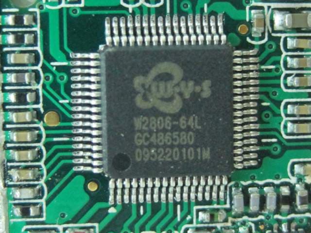
CCTT4841T-10
Jul 27, 2010Digital Audio Monitor (Baby Unit)
Equipment Class
DSS - Part 15 Spread Spectrum Transmitter
CCTT4256T-10
Jul 22, 2010Digital Video Monitor (Baby Unit)
Equipment Class
DSS - Part 15 Spread Spectrum Transmitter
CCTT4256R-10
Jul 21, 2010Digital Video Monitor (Parent Unit)
Equipment Class
DSS - Part 15 Spread Spectrum Transmitter