CEXFW10Camera Remote Control
Quantum Instruments Inc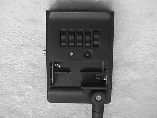
Click to zoom
Application Details
- Equipment Class
- DSC - Part 15 Security/Remote Control Transmitter
- Date of Grant
- Oct 23, 2000
- Application Purpose
- Original Equipment
- Date of Application
- Jun 27, 2000
- Equipment Note
- Camera Remote Control
- Frequency Range
- 433.92000000 - 433.92000000
- Company
- Quantum Instruments Inc
- Country
- United States
Documents & Files
Document Text
Text extracted from the exhibit documents filed with the FCC. Open a document above to read the original.
Users Manual
FW-10 Instructions and Housing Label Revised: 06 June 2000 ADVANCE COPY OF INSTRUCTIONS PROPRIETARY TO QUANTUM INSTRUMENTS INC. DO NOT COPY. SHRED. 1.0 Introduction We would like to introduce you to Delta’s unique ability to control your photo gear, wirelessly. Delta makes a two-way link be tw een yo ur ca mera, flash, a nd yo u. Le t’s say yo u’re using the Delta s yste m for wireless flash sync. The remote Delta unit will send back confirmation that it received the trigger signal! Delta provides wireless sync and/or wireless shutter control. And, Delta provides wireless TTL control of remote Qflash’s. Delta controls four independent Zones for wireless flash or motor drive. You can activate any one Zone, or any combination of Zones 1,2,3 and 4. There are 15 possible Zone combinations, plus one that shuts off all Zones. Switch your lighting instantly, remotely. Shoot cameras, or combinations of them, from your remote position. Delta also has eight unique S ystem codes. Delta units set to one System cannot activate Deltas set to different Systems. You control the System code to make Delta units work together or independently, as required. Each Delta can be selected to send, receive, or relay commands to your equipment.. For example, four Deltas can become two remote send/receive Systems , or they can become one System with one sender and three receivers. If you need extremely long-range wireless control, Deltas can relay comma nds to farther Delta units. You need only one type of Delta and fewer of them than with conventional wireless triggers. Delta is very small and light and mounts easily to cameras, brackets, poles, and tripod legs. Adapter cords are available for all popular cameras and flashes. A Universal Module (Uni-Mod), though not required, allow s you to hot s ync Delta directly fro m ca mera ho t shoes . There are many more useful features of Delta and we encourage you to read on! IMPORTANT - CAUTION Changes or modifications to this equipme nt could void your authority to use this product under the equipment authorization granted by the regulating agency or agencies. [This copy to appear in the instructions] This device complies with RSS-210 of Industry & Science Canada. Operation is subject to the following two conditions: 1) this device may not cause harmful interference, and 2) this device must accept any interference including that which may cause undesired operation. [---LABEL FOR HOUSING---] [This copy printed on the back face of the product...white lettering on black] FCC ID: CEXFW10 QUANTUM INSTRUMENTS INC. mode l FW-10 This device complies with Part 15 of the FCC Rules. Operation is subject to these conditions: 1) this device may not cause harmful interference, and 2) this device must accept any interference received including that which may cause undesired operation 2.0 System code and Zone set up 2.1 Locate the system code switch on the left side of Delta. Set it by rotating with your small finger. Set all Delta units that will operate together to the same system code, 0 through 7. Put AAA batteries in all units. Set one Delta to “TX” and any number of other Delta units to “RX”. TX means transmit, or send; RX means receive. Select one or more Zones on the TX. Set one (or more) of those Zones ON on each RX unit. 2.2 Turn on the units. TX Status blinks red once every two seconds. RX units blink green once every two seconds. Low batteries are indicated by 3 quick blinks every 3 seconds. Open the antennas so that they are approximately vertical to the ground. See Section 6.0, Mounting Delta. Press “TEST” on the TX Delta to confirm that all units are working. All RX Deltas’ Status should light green for as long as yo u hold TEST. If you will use the Uni-Mod, connect it now. 3.0 Remote Flash Set-up 3.1 TX Delta: Connect a sync-in cord from your camera PC nipple to Delta Sync-In. Set the Local/Relay switch to Local. You ma y also use the Uni- Mod to ho t s ync to the ca mera ho t shoe. If you want to sync a “local” flash as well as a remote one, connect the flash manufacturer’s PC sync cord to the Sync-Out PC nipple on the TX Delta, and set the Local/Relay switch to Local. 3.2 RX Delta: Connect the PC sync cord supplied by your flash’s manufacturer to the Sync-Out PC nipple on the RX Delta. 4.0 Remote Shutter Set-up 4.1 RX Delta: Connect a Motor Drive Cord (see Appendix C) from Delta MD-out to your camera motor drive. 4.2 TX: Delta: Press TEST and hold to activate the camera motor drive. Some cameras will require time to “wake-up” and auto focus before they release the shutter. Test before you shoot with film. 5.0 Confirmation Signals When an RX unit receives a valid signal, it sends a confirmation signal back to the TX unit. A valid signal is one that matches the same Zone and System codes on both RX and TX units. When the TX unit receives confirmation, Status lights steadily for about 1 second. If the TX receives no confirmation signal, Status will only blink. When controlling two or more RX units, simultaneous confirmation is not possible. Instead, set the RX units on different Zones (same System code). Turn on one TX Zone at a time to test the radio links. When yo u take yo ur pictures, turn o n all the T X Zo nes yo u desire to activate. When using Special Applications, Section 9, the confirmation signal operates a little differently. See the instructions with those set-ups. The Status confirmation is very useful for testing your radio links or for troubleshooting. See the Troubleshooting section for more details. 6.0 Mounting Delta 6.1 Physical Mounting Pole Mount Clamp – Item 513: this is included with your Delta. Attach it to the back of Delta and clamp it around any pole, leg, or structure where the antenna can be opened away from metal objects. Mounting directly to a bracket Mounting with the Uni-Mod To camera hot shoe To a “dead” shoe Mounting with velcro-type tape. 6.2 Notes on Antenna orientation. At close range (about 50’ or 16m) antenna orientation is not cr…
Text truncated - open the document above for the full version.
Block Diagram
Quantum Instruments Inc. FW10 Block Diagram • Flash Camera Camera Fig 1. Circuit Block Diagram 433.9 MHz 50kps data Rate with 50kps ASK modulation 3.3V DC Fig 2. Frequency and Signal Path Block Diagram Transceiver (TR3000) Micro- controller T rigger Circuit Driver Circuit DC-DC Converter Selector Switches Transceiver TR3000 Micro- controller DC-DC Converter 150KHz 4MHz Clock
ID Label/Location Info
FCC ID: CEXFW10 QUANTUM INSTRUMENTS INC. model FW-10 This device complies with Part 15 of the FCC Rules. Operation is subject to these conditions: 1) this device may not cause harmful interference, and 2) this device must accept any interference received including that which may cause undesired operation
Operational Description
FW-10 Instructions and Housing Label Revised: 06 June 2000 ADVANCE COPY OF INSTRUCTIONS PROPRIETARY TO QUANTUM INSTRUMENTS INC. DO NOT COPY. SHRED. 1.0 Introduction We would like to introduce you to Delta’s unique ability to control your photo gear, wirelessly. Delta makes a two-way link be tw een yo ur ca mera, flash, a nd yo u. Le t’s say yo u’re using the Delta s yste m for wireless flash sync. The remote Delta unit will send back confirmation that it received the trigger signal! Delta provides wireless sync and/or wireless shutter control. And, Delta provides wireless TTL control of remote Qflash’s. Delta controls four independent Zones for wireless flash or motor drive. You can activate any one Zone, or any combination of Zones 1,2,3 and 4. There are 15 possible Zone combinations, plus one that shuts off all Zones. Switch your lighting instantly, remotely. Shoot cameras, or combinations of them, from your remote position. Delta also has eight unique S ystem codes. Delta units set to one System cannot activate Deltas set to different Systems. You control the System code to make Delta units work together or independently, as required. Each Delta can be selected to send, receive, or relay commands to your equipment.. For example, four Deltas can become two remote send/receive Systems , or they can become one System with one sender and three receivers. If you need extremely long-range wireless control, Deltas can relay comma nds to farther Delta units. You need only one type of Delta and fewer of them than with conventional wireless triggers. Delta is very small and light and mounts easily to cameras, brackets, poles, and tripod legs. Adapter cords are available for all popular cameras and flashes. A Universal Module (Uni-Mod), though not required, allow s you to hot s ync Delta directly fro m ca mera ho t shoes . There are many more useful features of Delta and we encourage you to read on! IMPORTANT - CAUTION Changes or modifications to this equipme nt could void your authority to use this product under the equipment authorization granted by the regulating agency or agencies. [This copy to appear in the instructions] This device complies with RSS-210 of Industry & Science Canada. Operation is subject to the following two conditions: 1) this device may not cause harmful interference, and 2) this device must accept any interference including that which may cause undesired operation. [---LABEL FOR HOUSING---] [This copy printed on the back face of the product...white lettering on black] FCC ID: CEXFW10 QUANTUM INSTRUMENTS INC. mode l FW-10 This device complies with Part 15 of the FCC Rules. Operation is subject to these conditions: 1) this device may not cause harmful interference, and 2) this device must accept any interference received including that which may cause undesired operation 2.0 System code and Zone set up 2.1 Locate the system code switch on the left side of Delta. Set it by rotating with your small finger. Set all Delta units that will operate together to the same system code, 0 through 7. Put AAA batteries in all units. Set one Delta to “TX” and any number of other Delta units to “RX”. TX means transmit, or send; RX means receive. Select one or more Zones on the TX. Set one (or more) of those Zones ON on each RX unit. 2.2 Turn on the units. TX Status blinks red once every two seconds. RX units blink green once every two seconds. Low batteries are indicated by 3 quick blinks every 3 seconds. Open the antennas so that they are approximately vertical to the ground. See Section 6.0, Mounting Delta. Press “TEST” on the TX Delta to confirm that all units are working. All RX Deltas’ Status should light green for as long as yo u hold TEST. If you will use the Uni-Mod, connect it now. 3.0 Remote Flash Set-up 3.1 TX Delta: Connect a sync-in cord from your camera PC nipple to Delta Sync-In. Set the Local/Relay switch to Local. You ma y also use the Uni- Mod to ho t s ync to the ca mera ho t shoe. If you want to sync a “local” flash as well as a remote one, connect the flash manufacturer’s PC sync cord to the Sync-Out PC nipple on the TX Delta, and set the Local/Relay switch to Local. 3.2 RX Delta: Connect the PC sync cord supplied by your flash’s manufacturer to the Sync-Out PC nipple on the RX Delta. 4.0 Remote Shutter Set-up 4.1 RX Delta: Connect a Motor Drive Cord (see Appendix C) from Delta MD-out to your camera motor drive. 4.2 TX: Delta: Press TEST and hold to activate the camera motor drive. Some cameras will require time to “wake-up” and auto focus before they release the shutter. Test before you shoot with film. 5.0 Confirmation Signals When an RX unit receives a valid signal, it sends a confirmation signal back to the TX unit. A valid signal is one that matches the same Zone and System codes on both RX and TX units. When the TX unit receives confirmation, Status lights steadily for about 1 second. If the TX receives no confirmation signal, Status will only blink. When controlling two or more RX units, simultaneous confirmation is not possible. Instead, set the RX units on different Zones (same System code). Turn on one TX Zone at a time to test the radio links. When yo u take yo ur pictures, turn o n all the T X Zo nes yo u desire to activate. When using Special Applications, Section 9, the confirmation signal operates a little differently. See the instructions with those set-ups. The Status confirmation is very useful for testing your radio links or for troubleshooting. See the Troubleshooting section for more details. 6.0 Mounting Delta 6.1 Physical Mounting Pole Mount Clamp – Item 513: this is included with your Delta. Attach it to the back of Delta and clamp it around any pole, leg, or structure where the antenna can be opened away from metal objects. Mounting directly to a bracket Mounting with the Uni-Mod To camera hot shoe To a “dead” shoe Mounting with velcro-type tape. 6.2 Notes on Antenna orientation. At close range (about 50’ or 16m) antenna orientation is not cr…
Text truncated - open the document above for the full version.
Parts List/Tune Up Info
QUANTUM FW10 PARTS LIST file: FW10PARTLIST.xls Line # Des Parts # L1 ANTENNA LINX TECH ANT-433-PW-LP L3 INDUCTOR 220NH SMT0805 COILCRAFT 0805CS-221XJ L4 INDUCTOR 56NH SMT0805 COILCRAFT 0805CS-560XJ L5 CAP 27pf 5% 25V CERAMIC NPO SMT0603 L6 CHIP BEAD FAIR-RITE 2506031217YO SMT0603 L7 RES 10K 5% 1/10W OR 1/16W THICK FILM SMT0603 L8 CAP 4700pf 5% 25V CERAMIC X7R SMT0603 L9 CAP 0.015uf 5% 16V CERAMIC X7R SMT0603 L10 CAP 5600pf 5% 25V CERAMIC X7R SMT0603 L11 RES 100K 1% 1/10W OR 1/16W THICK FILM SMT0603 L12 RES 100K 1% 1/10W OR 1/16W THICK FILM SMT0603 L13 RES 100K 1% 1/10W OR 1/16W THICK FILM SMT0603 L14 RES 160K 1% 1/10W OR 1/16W THICK FILM SMT0603 L15 RES 1M 5% 1/10W OR 1/16W THICK FILM SMT0603 L16 RES 100OHM 5% 1/10W OR 1/16W THICK FILM SMT0603 L17 CAP 100pf 5% 25V CERAMIC NPO SMT0603 L18 CAP 10uf 10% 16V TANTALUM SMT B(3528) NEMCO L19 RES 4.7K 5% 1/10W OR 1/16W THICK FILM SMT0603 L20 RES 24K 5% 1/10W OR 1/16W THICK FILM SMT0603 L21 RES 150K 5% 1/10W OR 1/16W THICK FILM SMT0603 L23 CAP 10uf 10% 16V TANTALUM SMT B(3528) NEMCO L24 CAP 0.1uf 10% 50V CERAMIC X7R SMT0805 L25 RES 150OHM 5% 1/10W OR 1/16W THICK FILM SMT0603 L26 SWITCH DPDT MMK MMS-BD-2-2N L27 LED BICOLOR L3WEGW KINGBRIGHT L28 CAP 10uf 10% 16V TANTALUM SMT B(3528) NEMCO L30 TRANSISTOR ZETEX FMMT458 SOT23 L31 RES 47K 5% 1/10W OR 1/16W THICK FILM SMT0603 L32 TRANSISTOR MMBT4126 L33 RES 1K 5% 1/10W OR 1/16W THICK FILM SMT0603 L34 RES 20K 5% 1/10W OR 1/16W THICK FILM SMT0603 L35 CAP 0.1uf 10% 50V CERAMIC X7R SMT0805 L36 RES 10K 5% 1/10W OR 1/16W THICK FILM SMT0603 L37 DIODE SCHOTTKY SS12/CMSH1-20M/FM5817 SMTDO-214AC GENERAL/CENTRAL/RECTRON L38 SWITCH PUSHBTN SHIN WAY DTS-66KB WEALTH METAL TC-0109 L39 PC CONNECTOR 109-B110 L40 2.5MM STEREO JACK SIMULA AJ-402 SC PRECISION SCJ-0253A-2 L41 TRANSISTOR ZETEX FZT857 SOT223 L42 TRANSISTOR ZETEX FZT857 SOT223 L43 RES 330OHM 5% 1/10W OR 1/16W THICK FILM SMT0603 L44 RES 330OHM 5% 1/10W OR 1/16W THICK FILM SMT0603 L45 RES 2K 5% 1/10W OR 1/16W THICK FILM SMT0603 L46 CAP 0.1uf 10% 50V CERAMIC X7R SMT0805 L47 CAP 0.1uf 10% 50V CERAMIC X7R SMT0805 L48 CAP 0.1uf 10% 50V CERAMIC X7R SMT0805 L49 RES 1K 5% 1/10W OR 1/16W THICK FILM SMT0603 L50 RES 1K 5% 1/10W OR 1/16W THICK FILM SMT0603 L51 TRANSISTOR ZETEX FMMT458 SOT23 L52 TRANSISTOR ZETEX FMMT458 SOT23 L53 TRANSISTOR ZETEX FMMT458 SOT23 L54 TRANSISTOR ZETEX FMMT458 SOT23 L55 RES 10OHM 5% 1/10W OR 1/16W THICK FILM SMT0603 L56 RES 10OHM 5% 1/10W OR 1/16W THICK FILM SMT0603 L57 3.5MM PHONO JACK S.C. PRECISION SCJ0357B RDI RSJ-370 L58 DIODE SCHOTTKY SS12/CMSH1-20M/FM5817 SMTDO-214AC GENERAL/CENTRAL/RECTRON L59 DIODE SCHOTTKY SS12/CMSH1-20M/FM5817 SMTDO-214AC GENERAL/CENTRAL/RECTRON L60 RES 200K 1% 1/10W OR 1/16W THICK FILM SMT0603 L61 TRANSISTOR MOT MUN 5214T1 or ROHM DTC114YUA SOT-323 (SC-70) L62 RES 20K 5% 1/10W OR 1/16W THICK FILM SMT0603 L63 DIODE SCHOTTKY SS12/CMSH1-20M/FM5817 SMTDO-214AC GENERAL/CENTRAL/RECTRON L64 TRANSISTOR MOT MUN 5214T1 or ROHM DTC114YUA SOT-323 (SC-70) L65 TRANSISTOR MOT MUN 5214T1 or ROHM DTC114YUA SOT-323 (SC-70) L66 MICROCONTROLLER ATMEL AT90S4414-4AC SMT TQFP44 L69 RESONATOR SMT PBRC-4.00B AVX L70 RES 4.7K 5% 1/10W OR 1/16W THICK FILM SMT0603 L71 VOLTAGE SUPERVISOR TI TPS3809L30 or MAXIM MAX809S SOT23 L72 CAP 0.1uf 10% 50V CERAMIC X7R SMT0805 L73 CAP 10uf 10% 10v CERAMIC X5R SMT1210 TDK C3225X5R1A106K L74 DC-DC CONVERTER MAXIM MAX1678EUA SMT UMAX L75 RES 10OHM 5% 1/10W OR 1/16W THICK FILM SMT0603 L76 DIODE SCHOTTKY SS12/CMSH1-20M/FM5817 SMTDO-214AC GENERAL/CENTRAL/RECTRON L77 INDUCTOR 47UH SMT ABC SDS0804-470K L78 CAP 10uf 10% 10v CERAMIC X5R SMT1210 TDK C3225X5R1A106K L79 RES 200K 1% 1/10W OR 1/16W THICK FILM SMT0603 L80 RES 56K 1% 1/10W OR 1/16W THICK FILM SMT0603 L81 RES 200K 1% 1/10W OR 1/16W THICK FILM SMT0603 L82 DIODE CMR1-02M OR S1D SMTDO-214AC CENTRAL OR GENERAL L83 SWITCH DPDT MMK MMS-BD-2-2N L84 CAP 0.1uf 10% 50V CERAMIC X7R SMT0805 L85 VOLTAGE REGULATOR NATIONAL LM3480 SOT23 L86 CAP 0.1uf 10% 50V CERAMIC X7R SMT0805 L87 DIODE CMR1-02M or S1D SMTDO-214AC CENTRAL OR GENERAL L89 DIODE SCHOTTKY SS12/CMSH1-20M/FM5817 SMTDO-214AC GENERAL/CENTRAL/RECTRON L90 JACK MIN DIN 8 pin L91 TRANSISTOR MOT MUN 5214T1 or ROHM DTC114YUA SOT-323 (SC-70) L92 RES 20K 5% 1/10W OR 1/16W THICK FILM SMT0603 L93 CAP 100uf 20% 6.3V TANTALUM SMTC(6032) L95 8POS ROT DIP SWITCH SHIN WAY RR31311 PLAIMAE RR313 8 POS ROTARY DIP SWITCH L96 HEADER 5P JST B5B-ZR L97 SWITCH SPDT RAINBOW SS-12E01G2 E-SWITCH EG1218 L98 SWITCH SPDT RAINBOW SS-12E01G2 E-SWITCH EG1218 L99 SWITCH SPDT RAINBOW SS-12E01G2 E-SWITCH EG1218 L100 SWITCH SPDT RAINBOW SS-12E01G2 E-SWITCH EG1218 L101 SWITCH SPDT RAINBOW SS-12E01G2 E-SWITCH EG1218 L102 RES 1M 5% 1/10W OR 1/16W THICK FILM SMT0603 L103 RES 1M 5% 1/10W OR 1/16W THICK FILM SMT0603 L107 DIODE SCHOTTKY SS12/CMSH1-20M/FM5817 SMTDO-214AC GENERAL/CENTRAL/RECTRON L110 TRANSCEIVER RFM TR3000 SM-20L L112 battery clip L113 1.3MM DC JACK SUN RISE DC-041-PT2 SC PRECISION SCD420ACS005000 L115 DIODE SCHOTTKY SS12/CMSH1-20M/FM5817 SMTDO-214AC GENERAL/CENTRAL/RECTRON L117 RES 100OHM 5% 1/10W OR 1/16W THICK FILM SMT0603 L118 TRANSISTOR MOT MUN 5214T1 or ROHM DTC114YUA SOT-323 (SC-70)
Schematics
L40 RS J
Test Report
Test Report No. R-8568-1 FCC ID: CEXFW10 APPLICANT Quantum Instruments Inc. 1075 Stewart Avenue Garden City, NY 11530 MANUFACTURER Quantum Instruments Inc. 1075 Stewart Avenue Garden City, NY 11530 TEST SPECIFICATION:FCC Rules and Regulations Part 15, Subpart C, Para. 15.231 TEST PROCEDURE:ANSI C63.4:1992 TEST SAMP LE DESCRIP TION BRANDNAME: Quantum MODEL: FW10 TYPE: Pulsed Transmitter POWER REQUIREMENTS: 3 VDC derived from CUI Stack, AC Adapter Model DPP060020-P1-SZ FREQUENCY OF OPERATION: 433.92 MHz TESTS P ERFORMED Para. 15.207(a), Conducted Emissions Para. 15.231(a), Radiated Emissions, Fundamental and Harmonics Para. 15.231(b), Radiated Emissions, Spurious Case Para. 15.231(c), Occupied Bandwidth REPORT OF MEASUREMENTS Applicant: Quantum Instruments Inc. Device:AM Pulsed Transmitter FCC ID: CEXFW10 Power Requirements: 3VDC Test Report No. R-8568-1 FCC ID: CEXFW10 Applicable Rule Section:Part 15, Subpart C, Section 15.231 Test Report No. R-8568-1 FCC ID: CEXFW10 REPORT OF MEASUREMENTS (continued) TEST RESULTS 15.207(a):The radio frequency voltage that was conducted back on to the AC power line on any frequency/frequencies within the bandwidth of 450kHz to 30MHz did not exceed 250 microvolts. 15.231 (a):This device is used as a remote control of photography equipment. 15.231 (a)(1) &The transmitter is manually operated and ceases transmission within 5 15.231(a)(2):seconds after deactivation. 15.231 (a)(3):The transmitter does not perform periodic transmissions. 15.231 (b):The fundamental field strength did not exceed 11000 μV/M (Average) at a test distance of 3 meters. In addition, the requirements of section 15.35 for averaging pulsed emissions and for limiting peak emissions were met. The field strength of harmonic and spurious emissions did not exceed 1100 μV/M (AVERAGE). DETERMINATION OF FIELD STRENGTH LIMITS The field strength limits shown below are found in Section 15.231. Frequency Limit F1=2603750 =L1 Fo=433.92Lo F2=47012500 =L2 The formula below was utilized to determine the limits: Limit = L1 + [(Fo-F1)(L2-L1)/(F2-F1)] Solving yields: Fundamental Limit= 11,000 μV/M (AVERAGE) @ 3 Meters Harmonic Limit= 1,100 μV/M (AVERAGE) @ 3 Meters Test Report No. R-8568-1 FCC ID: CEXFW10 REPORT OF MEASUREMENTS (continued) DUTY CYCLE DETERMINATION The spectrum analyzer was set to a 0 Hz span with a sweep time of 100 mSec at the fundamental transmitter frequency. The worst case duty cycle during any 100 mSec period was then measured. The information below is a calculation of duty cycle based on the measured values obtained: (8 x 15 μ sec) = 0.120 mSec (10) x 20 μ sec = 0.200 mSec (1) x 30 μ sec = 0.030 mSec (1) x 40 μ sec = 0.040 mSec Duty Cycle Correction Factor = 20 log (0.0039) = -48.2 dB SPECTRUM ANALYZER DESENSITIZATION CONSIDERATIONS Due to the nature of the emissions being measured, care was taken to ensure that the resolution bandwidth of the spectrum analyzer was adequate to provide accurate measurements. The following formula was utilized: Setting pulse desensitization equal to zero and utilizing the minimum observed pulse width of 20μs yields a minimum required bandwidth of 33.3 kHz. FCC specified bandwidths of 100kHz and 1MHz were utilized below and above 1GHz, respectively. GENERAL NOTES 1. All readings were taken utilizing a peak detector function at a test distance of 3 meters. 2. The duty cycle was applied to the peak readings in order to determine the average value of the emissions. 3. All measurements were made with 3 VDC being derived from an AC Adapter. 4. The frequency range was scanned from 30 MHz to 4.4 GHz. All emissions not reported were more than 20 dB below the specified limit. Test Report No. R-8568-1 FCC ID: CEXFW10 EQUIPMENT LISTS Radiated Emissions, Fundamental and Harmonics, 430MHz-4.5GHz ENTypeManufacture rDe scriptionMode l No.Cal Date Due Date 067Open Area Test SiteRetlif3 MeterRNY10/15/199710/15/2000 128CDouble Ridge GuideEaton Corporation1 GHz - 18 GHz9600109/16/199909/16/2000 133Broadband Pre-AmplifierElectro-Metrics10 kHz - 1 GHz, 26dBBPA-100006/22/199906/22/2000 141Spectrum AnalyzerHewlett Packard100 Hz - 40 GHz8566B03/20/200009/20/2000 141AGraphics PlotterHewlett PackardN/A7470A03/08/200003/08/2001 141BQuasi-Peak AdaptorHewlett Packard100 Hz - 1 GHz85650A03/20/200009/20/2000 206B6.0 dB AttenuatorTexscan0 - 1.0 GHzFP-50 - 6 dB06/22/199906/22/2000 443Log Periodic AntennaElectro-Metrics200 MHz - 1000 MHzLPA-2501/17/200001/17/2001 543PreamplifierHewlett Packard1.0 GHz - 26.5 GHz8449B06/16/199906/16/2001 Radiated Emissions, Spurious, and Occupied Bandwidth, 430MHz-4.5GHz ENTypeManufacture rDe scriptionMode l No.Cal Date Due Date 067Open Area Test SiteRetlif3 MeterRNY10/15/199710/15/2000 128CDouble Ridge GuideEaton Corporation1 GHz - 18 GHz9600109/16/199909/16/2000 133Broadband Pre-AmplifierElectro-Metrics10 kHz - 1 GHz, 26dBBPA-100006/22/199906/22/2000 141Spectrum AnalyzerHewlett Packard100 Hz - 40 GHz8566B03/20/200009/20/2000 141AGraphics PlotterHewlett PackardN/A7470A03/08/200003/08/2001 141BQuasi-Peak AdaptorHewlett Packard100 Hz - 1 GHz85650A03/20/200009/20/2000 206B6.0 dB AttenuatorTexscan0 - 1.0 GHzFP-50 - 6 dB06/22/199906/22/2000 443Log Periodic AntennaElectro-Metrics200 MHz - 1000 MHzLPA-2501/17/200001/17/2001 543PreamplifierHewlett Packard1.0 GHz - 26.5 GHz8449B06/16/199906/16/2001 Conducted Emissions, Transmit, 450kHz-30MHz ENTypeManufacture rDe scriptionMode l No.Cal Date Due Date 078LISNSolar Electronics10 kHz - 30 MHz8028-50-TS24BNC04/27/200004/27/2001 141Spectrum AnalyzerHewlett Packard100 Hz - 40 GHz8566B03/20/200009/20/2000 141AGraphics PlotterHewlett PackardN/A7470A03/08/200003/08/2001 141BQuasi-Peak AdaptorHewlett Packard100 Hz - 1 GHz85650A03/20/200009/20/2000 2 0 2Tra ns ie nt Limite rHe wle tt P a c k a rd.009 MHz - 200 MHz11947A07/19/199907/19/2000 513LISNSolar Electronics10 kHz - 30 MHz8028-50-TS24BNC04/27/200004/27/2001 Test Report No. R-8568-1 FCC ID: CEXFW10 FCC 15.207(a) Conducted Emissions Please refer to separate electronic fil…
Text truncated - open the document above for the full version.
Test Report
Retlif Testing Laboratories R Data Sheet 1 of 4 Test Method: FCC Part 15 Subpart C Radiated Emissions, Fundamental & Harmonic Emissions Customer: Quantum Industries Job No. R-8568-1 Test Sample: 433.92MHz AM Pulsed Transmitter Paragraph: 15.231 Model No.: FW10 FCC ID: CEXFW10 Operating Mode: Continuously Transmitting a 433.92MHz Signal Technician: Peter Lananna Date: June 2, 2000 Notes: Test Distance: 3 Meters - Detector: Peak, Unless otherwise specified Test Freq. Antenna Pol./Height EUT Orientation Meter Reading Correction Factor Corrected Reading Converted Reading Peak Limit MHz (V/H)/Meters X / Y / Z dBuV dB dBuV/m uV/m uV/m 433.9 H / 1.0 X 88.0 -2.2 85.8 19498.4 110000 | H / 1.0 Y 92.9 -2.2 90.7 34276.8 | | H / 1.0 Z 89.6 -2.2 87.4 23442.3 | | V / 1.0 X 91.6 -2.2 89.4 29512.1 | | V / 2.0 Y 93.9 -2.2 91.7 38459.2 | 433.9 V / 2.0 0 Z 90.7 -2.2 88.5 26607.3 110000 867.8 H / 1.0 X 47.9 6.1 54.0 501.2 11000 | H / 1.0 Y 40.0 6.1 46.1 201.8* | | H / 1.0 Z 47.3 6.1 53.4 467.7 | | V / 1.5 X 51.5 6.1 57.6 758.6 | | V / 1.0 Y 40.0 6.1 46.1 201.8* | 867.8 V / 1.5 Z 50.9 6.1 57.0 707.9 11000 1301.7 H / 1.0 X 48.8 -5.3 43.5 149.6 500 | H / 1.0 Y 51.1 -5.3 45.8 195.0 | | H / 1.0 Z 53.7 -5.3 48.4 263.0 | | V / 2.0 X 51.1 -5.3 45.8 195.0 | | V / 1.5 Y 47.9 -5.3 42.6 134.9 | 1301.7 V / 1.5 Z 48.8 -5.3 43.5 149.6 500 1735.6 H / 1.0 X 39.0 -3.1 35.9 62.4* 11000 | H / 1.0 Y 39.0 -3.1 35.9 62.4* | | H / 1.0 Z 39.0 -3.1 35.9 62.4* | | V / 1.0 X 39.0 -3.1 35.9 62.4* | | V / 1.0 Y 39.0 -3.1 35.9 62.4* | 1735.6 V / 1.0 Z 39.0 -3.1 35.9 62.4* 11000 2169.5 H / 1.0 X 39.0 -1.6 37.4 74.1* 11000 | H / 1.0 Y 39.0 -1.6 37.4 74.1* | | H / 1.0 Z 39.0 -1.6 37.4 74.1* | | V / 1.0 X 39.0 -1.6 37.4 74.1* | | V / 1.0 Y 39.0 -1.6 37.4 74.1* | 2169.5 V / 1.0 Z 39.0 -1.6 37.4 74.1* 11000 The frequency range was scanned from 30 MHz to 4.5 GHz. All emissions not recorded were more Than 10 dB below the specified limit. Emissions from the EUT do not exceed the specified limits. *=Noise Floor Measurements (Minimum system sensitivity) Retlif Job Number R-8568-1 Retlif Testing Laboratories R Data Sheet 2 of 4 Test Method: FCC Part 15 Subpart C Radiated Emissions, Fundamental & Harmonic Emissions Customer: Quantum Industries Job No. R-8568-1 Test Sample: 433.92MHz AM Pulsed Transmitter Paragraph: 15.231 Model No.: FW10 FCC ID: CEXFW10 Operating Mode: Continuously Transmitting a 433.92MHz Signal Technician: Peter Lananna Date: June 2, 2000 Notes: Test Distance: 3 Meters Detector: Peak, unless otherwise specified Test Freq. Antenna Pol./Height EUT Orientation Meter Reading Correction Factor Corrected Reading Converted Reading Peak Limit MHz (V/H)-Meters X / Y / Z dBuV dB dBuV/m uV/m uV/m 2603.4 H / 1.0 X 39.0 0.6 39.6 95.5* 11000 | H / 1.0 Y 39.0 0.6 39.6 95.5* | | H / 1.0 Z 39.0 0.6 39.6 95.5* | | V / 1.0 X 39.0 0.6 39.6 95.5* | | V / 1.0 Y 39.0 0.6 39.6 95.5* | 2603.4 V / 1.0 Z 39.0 0.6 39.6 95.5* 11000 3037.3 H / 1.0 X 39.0 3.1 42.1 127.4* 11000 | H / 1.0 Y 39.0 3.1 42.1 127.4* | | H / 1.0 Z 39.0 3.1 42.1 127.4* | | V / 1.0 X 39.0 3.1 42.1 127.4* | | V / 1.0 Y 39.0 3.1 42.1 127.4* | 3037.3 V / 1.0 Z 39.0 3.1 42.1 127.4* 11000 3471.2 H / 1.0 X 39.0 7.1 46.1 201.8* 11000 | H / 1.0 Y 39.0 7.1 46.1 201.8* | | H / 1.0 Z 39.0 7.1 46.1 201.8* | | V / 1.0 X 39.0 7.1 46.1 201.8* | | V / 1.0 Y 39.0 7.1 46.1 201.8* | 3471.2 V / 1.0 Z 39.0 7.1 46.1 201.8* 11000 3905.1 H / 1.0 X 39.0 8.9 47.9 248.3* 500 | H / 1.0 Y 39.0 8.9 47.9 248.3* | | H / 1.0 Z 39.0 8.9 47.9 248.3* | | V / 1.0 X 39.0 8.9 47.9 248.3* | | V / 1.0 Y 39.0 8.9 47.9 248.3* | 3905.1 V / 1.0 Z 39.0 8.9 47.9 248.3* 500 4339.2 H / 1.0 X 39.0 9.8 48.8 275.4* 500 | H / 1.0 Y 39.0 9.8 48.8 275.4* | | H / 1.0 Z 39.0 9.8 48.8 275.4* | | V / 1.0 X 39.0 9.8 48.8 275.4* | | V / 1.0 Y 39.0 9.8 48.8 275.4* | 4339.2 V / 1.0 Z 39.0 9.8 48.8 275.4* 500 The frequency range was scanned from 30 MHz to 4.5 GHz. All emissions not recorded were more Than 10 dB below the specified limit. Emissions from the EUT do not exceed the specified limits. *=Noise Floor Measurements (Minimum system sensitivity) Retlif Job Number R-8568-1 Retlif Testing Laboratories R Data Sheet 3 of 4 Test Method: FCC Part 15 Subpart C Radiated Emissions, Fundamental & Harmonic Emissions Customer: Quantum Industries Job No. R-8568-1 Test Sample: 433.92MHz AM Pulsed Transmitter Paragraph: 15.231 Model No.: FW10 FCC ID: CEXFW10 Operating Mode: Continuously Transmitting a 433.92MHz Signal Technician: Peter Lananna Date: June 2, 2000 Notes: Test Distance: 3 Meters Duty Cycle: .05% Detector: Peak, unless otherwise specified Duty Cycle Correction: - 46.0dB Test Freq. Antenna Pol./Height EUT Orientation Peak Reading Correction Factor Corrected Reading Converted Reading Avg. Limit MHz (V/H)-Meters X / Y / Z dBuV dB dBuV/m uV/m uV/m 433.9 H / 1.0 X 85.8 -46.0 39.8 97.7 11000 | H / 1.0 Y 90.7 -46.0 44.7 171.8 | | H / 1.0 Z 87.4 -46.0 41.4 117.5 | | V / 1.0 X 89.4 -46.0 43.4 147.9 | | V / 2.0 Y 91.7 -46.0 45.7 192.8 | 433.9 V / 2.0 0 Z 88.5 -46.0 42.5 133.4 11000 867.8 H / 1.0 X 54.0 -46.0 8.0 2.5 1100 | H / 1.0 Y 46.1 -46.0 0.1 1.0* | | H / 1.0 Z 53.4 -46.0 7.4 2.3 | | V / 1.5 X 57.6 -46.0 11.6 3.8 | | V / 1.0 Y 46.1 -46.0 0.1 1.0* | 867.8 V / 1.5 Z 57.0 -46.0 11.0 3.5 1100 1301.7 H / 1.0 X 43.5 -46.0 -2.5 0.7 500 | H / 1.0 Y 45.8 -46.0 -0.2 1.0 | | H / 1.0 Z 48.4 -46.0 2.4 1.3 | | V / 2.0 X 45.8 -46.0 -0.2 1.0 | | V / 1.5 Y 42.6 -46.0 -3.4 0.7 | 1301.7 V / 1.5 Z 43.5 -46.0 -2.5 0.7 500 1735.6 H / 1.0 X 35.9 -46.0 -10.1 0.3* 1100 | H / 1.0 Y 35.9 -46.0 -10.1 0.3* | | H / 1.0 Z 35.9 -46.0 -10.1 0.3* | | V / 1.0 X 35.9 -46.0 -10.1 0.3* | | V / 1.0 Y 35.9 -46.0 -10.1 0.3* | 1735.6 V / 1.0 Z 35.9 -46.0 -10.1 0.3* 1100 2169.5 H / 1.0 X 37.4 -46.0 -8.6 0.4* 1100 | H / 1.0 Y 37.4 -46.0 -8.6 0.4* | | H / 1.0 Z 37.4 -46.0 -8.6 0.4* | | V / 1.0 X 37.4 -46.0 -8.6 0.4* | | V / 1.0 Y 37.4 -46.0 -8.6 0.4* | 2169.5 V / 1.0 Z 37.4 -46.0 -8.6 0.4* 1100 The frequency range was scanned from 30 MHz to 4.5 GHz. All emissions not recorded were more Than 10 dB b…
Text truncated - open the document above for the full version.
Test Report
Retlif Testing Laboratories R Retlif Job Number R-8568-1 Data Sheet 1 of 1 Test Method: FCC Part 15 Subpart C Radiated Emissions, Spurious, Paragraph 15.231(b) Customer: Quantum …
Text truncated - open the document above for the full version.
Contact Information
Applicant
Richard Shaper
Technical Contact
Retlif Testing LaboratoriesThomas J Schneider
[email protected]631-737-1500
795 Marconi Avenue · Ronkonkoma, New York · United States
Non-Technical Contact
Retlif Testing LaboratoriesMichelle White
[email protected]631-737-1500
Technical Specifications
| # | Rule Parts | Frequency Range | Power Output |
|---|---|---|---|
| 1 | 15C | 433.92 MHz - 433.92 MHz | - |
Other Applications from Quantum Instruments Inc
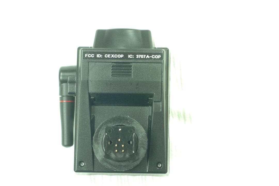
CEXCOP
Jun 05, 2012A Wireless Radio Commander Unit for Digital Cameras to Control Remote Flashes
Equipment Class
DSC - Part 15 Security/Remote Control Transmitter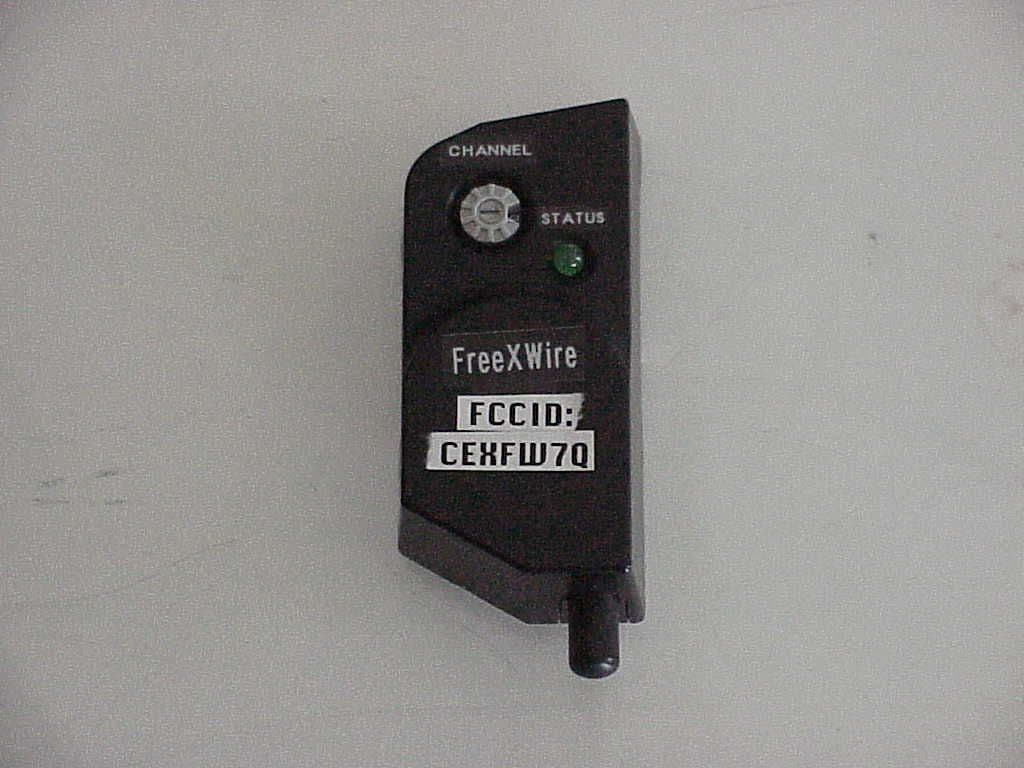
CEXFW7Q
Mar 07, 2005Wireless Flash for Camera
Equipment Class
CYY - Communications Receiver used w/Pt 15 Transmitter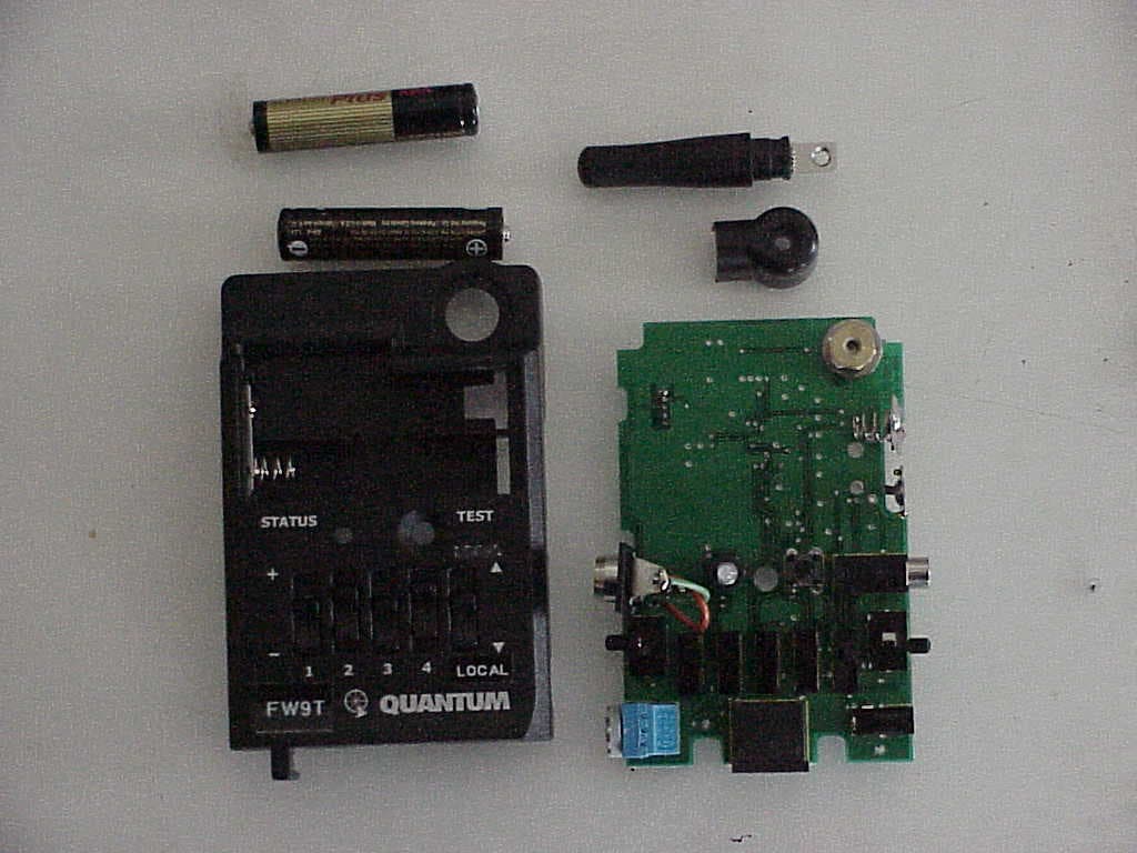
CEXFW9T
Mar 07, 2005Wireless Flash for Camera
Equipment Class
DSC - Part 15 Security/Remote Control TransmitterCEX8EH-505S
Oct 21, 1990DSC - Part 15 Security/Remote Control Transmitter
Equipment Class
DSC - Part 15 Security/Remote Control TransmitterCEX8EH-505R
Feb 25, 1990CRR - Superregenerative Receiver
Equipment Class
CRR - Superregenerative Receiver