CEXFW9TWireless Flash for Camera
Quantum Instruments Inc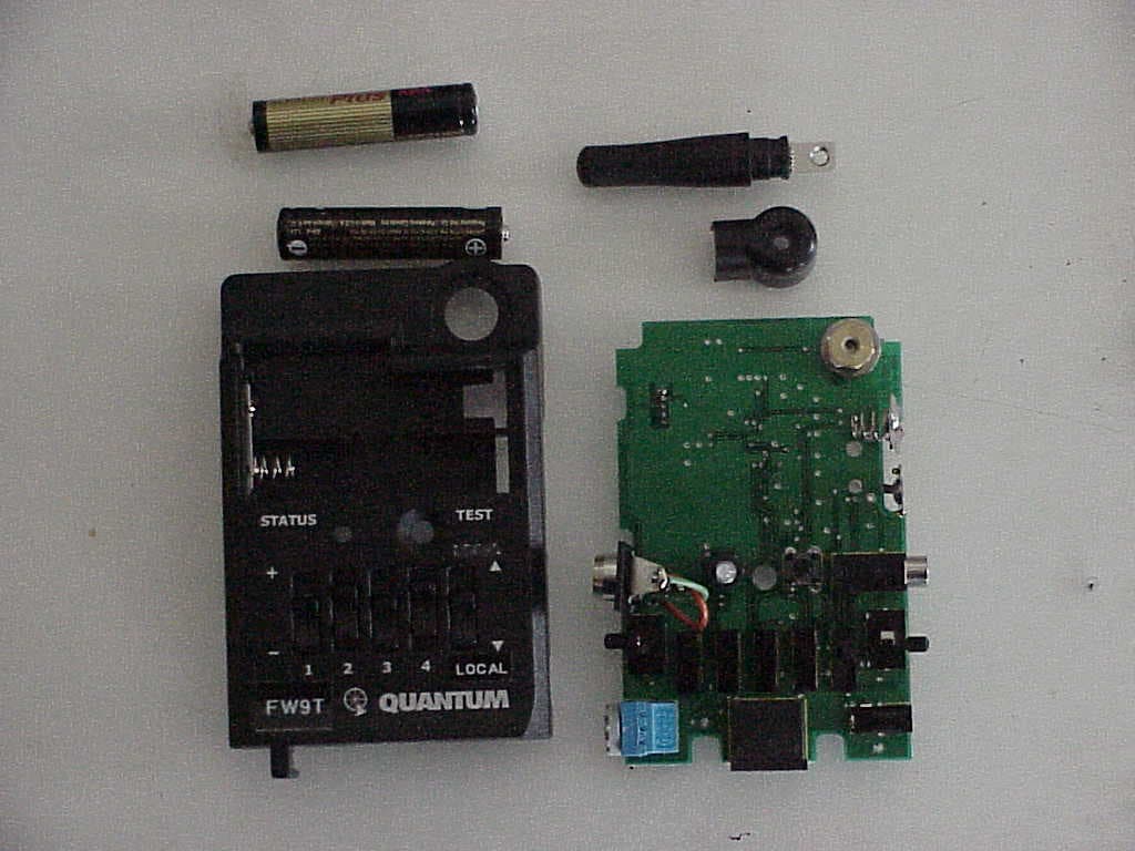
Click to zoom
Application Details
- Equipment Class
- DSC - Part 15 Security/Remote Control Transmitter
- Date of Grant
- Mar 07, 2005
- Application Purpose
- Original Equipment
- Date of Application
- Jan 10, 2005
- Equipment Note
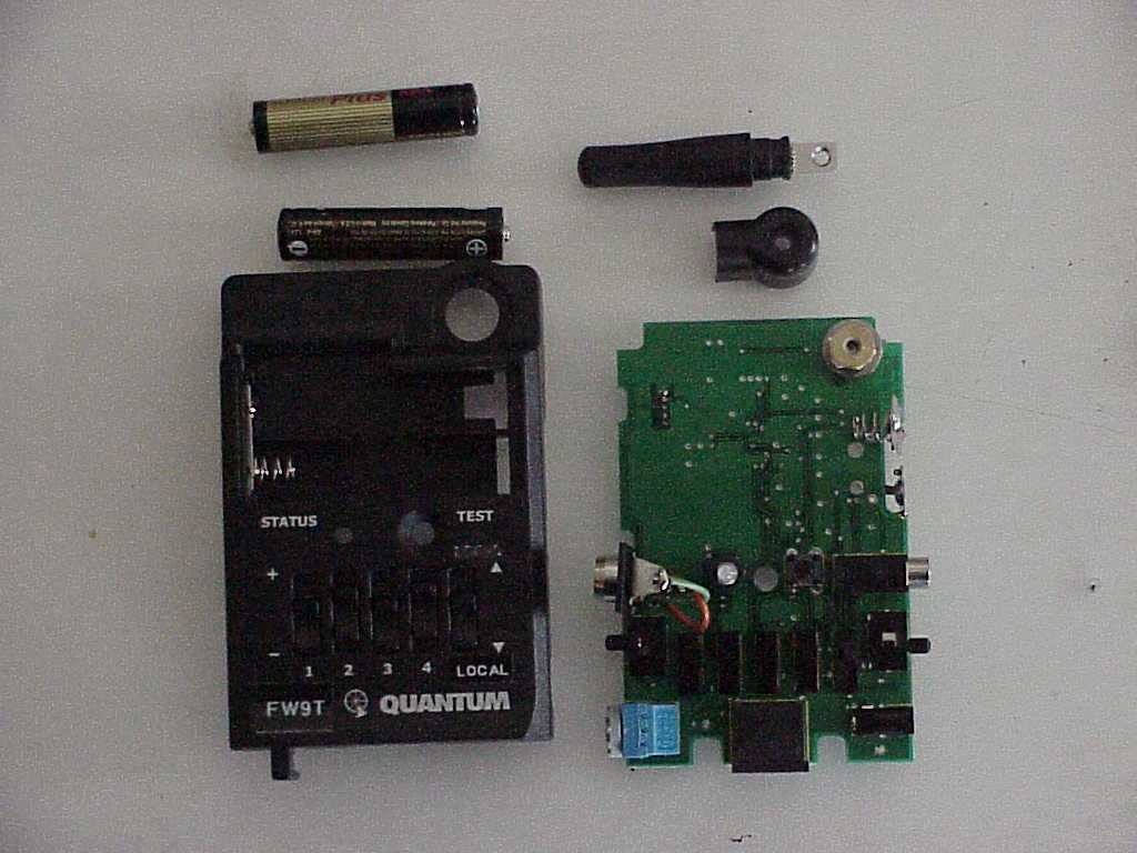
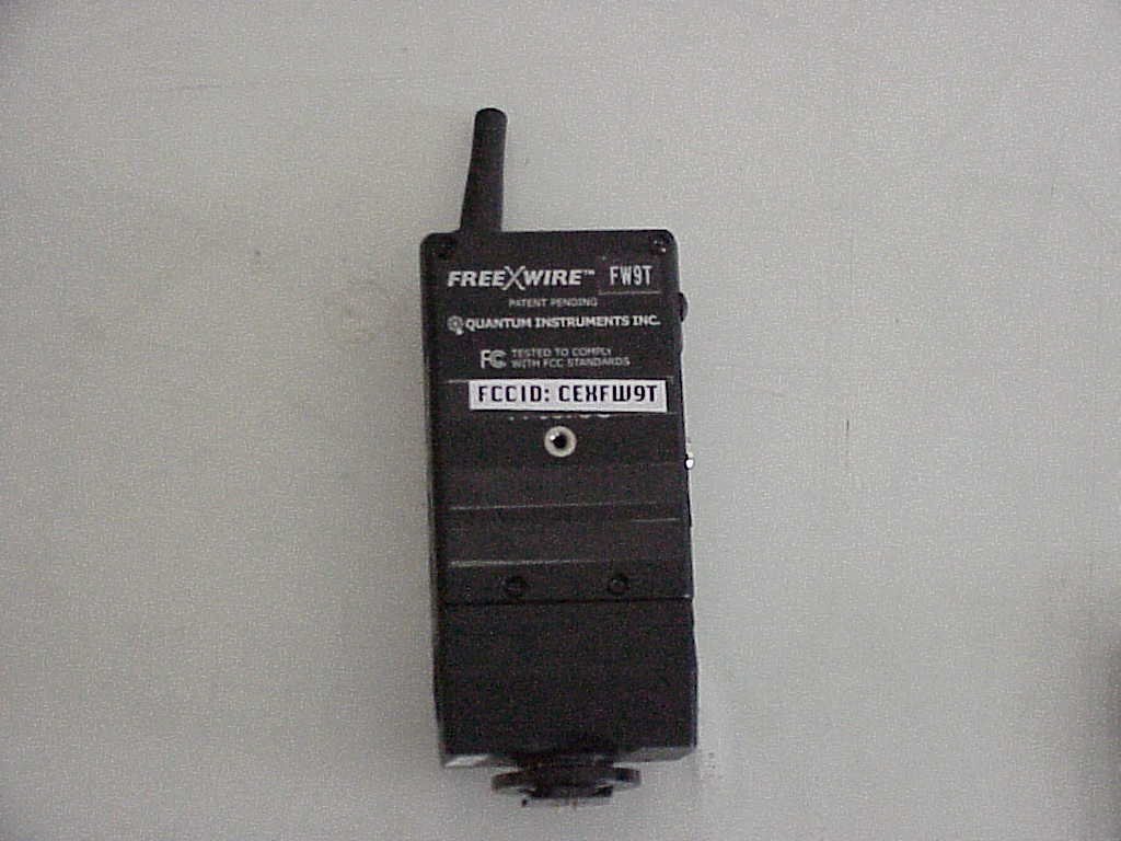
- Wireless Flash for Camera
- Frequency Range
- 433.90000000 - 433.90000000
- Company
- Quantum Instruments Inc
- Country
- United States
Documents & Files
Document Text
Text extracted from the exhibit documents filed with the FCC. Open a document above to read the original.
Users Manual
Instructions FreeXwire models FW8R and FW9T Digital Receiver/ Digital Transmitter / Digital Wireless TTL Flash and Camera Trigger Quantum Instruments Inc. 1.0 Introduction We introduce you to the newest additions to the FreeXwire system: Receiver FW8R and Transmitter FW9T. Transmitter FW9T emits higher power for extended range. Receiver FW8R has extra sensitivity and simplified operation. Both FW8R and FW9T are fully compatible with all FreeXwire system components including Receiver FW7Q and Transceiver FW10. FreeXwires provide wireless sync for remote flash and/or wireless shutter control for remote camera operation. FW8R and FW9T can provide wireless TTL flash control from digital and film cameras to Qflash T5d (Qflash 4d models can be upgraded). This wireless TTL feature also transmits the “pre-flash” signal for digital cameras. FreeXwire controls four independent Zones for wireless flash or motor drive. You can activate any one Zone, or any combination of Zones 1,2,3 and 4. Switch your lighting instantly, remotely. Select and trigger flash, cameras, or combinations of them, from your remote position. FreeXWire also has eight unique Channel Codes. FreeXwire units set to one Channel cannot activate FreeXwires set to different Channels. You control the Channel Code to make FreeXwire units work together or independently, as required. FreeXWire is very small and light and mounts easily to cameras, brackets, poles, and tripod legs. Sync and motor drive cords are available for popular cameras and flashes. You can mount Transmitter FW9T directly on camera hot shows using optional UniMod FW11 or Hot Shoe Adapter FW12. FreeXwire Instructions -- Contents: Section 1.0 Introduction 2.0 Channel Code and Zone set-up 3.0 Remote Flash set-up 4.0 Remote Shutter set-up (with or without on-camera flash) 5.0 Mounting FreeXwire 6.0 Qflash T4 Remote Operation 7.0 Wireless TTL and Wireless Auto with Qflash 8.0 Miscellaneous 9.0 FreeXWire Performance Guide Appendix A Sync-in connections- camera to FreeWire FW9T Appendix B Sync-out connections- Receiver FW8R to flash Appendix C Motor Drive cords- Receiver FW8R to camera Appendix D TTL Wireless Adapters for FreeWire FW9T Appendix E Miscellaneous connections Appendix F Specifications Customer Service Limited Warranty Included with FreeXwire model FW8R: Pole mounting kit, 2x AAA batteries, Instructions, Hook and loop mounting pads Included with FreeXwire model FW9T: 2x AAA batteries, Sync-in cord, Instructions All specifications and features are subject to change, updating, and improvements. ________________________________________________________________________________ Glossary_________________________________________________________________________ Receiver FW7Q -- a FreeXwire receiver unit dedicated for Qflash model T4 Receiver FW8R -- a FreeXwire receiver unit Transmitter FW9T -- a FreeXwire transmitter unit Transceiver FW10 -- a FreeXwire transceiver unit (can be set as transmitter or receiver). Hot Shoe Adapter FW12 -- a FreeXwire hot shoe adapter to mount FW9T on camera shoe Zones 1, 2, 3, and 4 -- wireless links that can be turned on or off to change lighting and camera activation Channels 0 thru 7 -- independent channels for separate FreeWire setups operating in the same area “Local” flash -- a flash close to the camera and connected with a sync cord “Remote” flash -- a flash at a distance from the camera and wirelessly synchronized 2.0 Channel Code and Zone set-up 2.1 Setting the Channel Code and Zones The Channel Codes allow FreeXwires to work together. Set all units that you want to work together to the same Channel Code. If you desire independent groups of FreeXwires (to work in the same area but not interfere), assign each group of FreeXwires its own Channel. The Channel dial is located on the left side. Rotate the dial to the desired Code, 0 through 7. To rotate, press the pad of your thumb on the dial and turn. Or, use a small screwdriver. Channels can be matched by number or by the position of the cutout in the Channel dial. Put AAA batteries in all units. Activate at least one Zone on both FW8R and FW9T by sliding Zone switches 1, 2, 3, and/or 4 up, towards the “+” symbol. Any FW8R and FW9T Zones that match will activate FW8R units each time the FW9T unit transmits. There are many possible combinations and you can change them as you work. To deactivate a Zone slide its switch down towards the “-“ symbol. OFF 1 2 ON RELAY 3 4 LOCAL 2.2 Turn on the units. Slide the power switch to ON. Status lights of FW9T units blink red slowly. FW8R units blink green slowly. Low batteries are indicated by 3 quick blinks every few seconds. Open the antennas so that they are approximately vertical. See Section 5.0, Mounting FreeWire. Press TEST on the Transmitter FW9T to confirm that all units are working. STATUS should light steadily on all FreeXwires FW8R’s for as long as you hold TEST (assuming correct Channel and Zone settings.) The optional Hot Shoe adapter FW12 may be connected to the Transmitter FW9T. The purpose of the Hot Shoe Adapter is only to provide hot shoe mounting and sync from a camera to a Transmitter FW9T. FW12 will not provide TTL control -- see the chart (Appendix D) for selection of QTTL and other TTL adapters. 3.0 Remote Flash set-up 3.1 Transmitter FW9T: Connect a sync-in cord from your camera PC nipple to FW9T Sync-In. Or use the optional FW12 to connect FreeWire to your camera’s hot shoe. (See Appendix A for other sync-in options.) If you want to sync a “local” flash as well as a remote one, connect the flash manufacturer’s PC sync cord to the Sync-Out PC nipple on Transmitter FW9T, and set the Local switch to “+”. To turn off the local flash, switch to “-“. If Qflash is the “local” flash, connect FW31 from Qflash to FW9T DIN socket or FW12 DIN socket. Then, Qflash can power the FW9T by setting the power switch to “off” (EXT). The battery will not be needed in the FW9T. 3.2 Receiver FW8R: Connect the PC sync cord supplied by your flash’…
Text truncated - open the document above for the full version.
Block Diagram
Fig 1. CEXFW9T Circuit Block Diagram RF Transmitter 433.92MHZ Micro- Controller 8MHZ Trigger Circuit DC-DC Converter Selector Switches Camera
Cover Letter(s)
Green Mountain Electromagnetics, Inc. GME (802)388-3390 Fax: (802)388-6279 Email: [email protected] 219 Blake Roy Road • Middlebury, VT 05753 3/3/05 Attn: Andy Leimer FCC 7435 Oakland Mills Road Columbia, MD 21046 Re: Confidentiality for FCC ID's CEXFW7Q, CEXFW8R and CEXFW9T This letter serves as an official request for confidentiality under FCC Rule 0.459. we have requested that the schematics required to be submitted with this application be witheld from public review. The documents contain company proprietary information that was developed exclusively at private expense for: Quantum Instruments, Inc. 1075 Stewart Ave. Garden City, NY 11530 Please call if you have any questions. Sincerely, Kyle R. Kowalczyk Agent/President
Operational Description
CE/IC/FCC PART 15 Certification Application for Quantum FW7Q, FW8R, FW9T Description of Product Operation Quantum Instruments Inc.’s FW7Q, FW8R and FW9T comprise a RF remote control system for trigger and control of photographic devices. FW7Q, FW8R are the receiver units. FW9T is a transmitter unit. FW7Q is dedicated for Quantum Qflash 4d and 5d series flashes. The FW7Q and FW8R receiver circuits consist of an antenna, a RF receiver, a micro-controller, function selector switch, driver circuit and DC-DC converter. The FW9T transmitter circuit consists of an antenna, a RF transmitter, a micro-controller, function selector switch, trigger circuit and DC-DC converter. The antenna is a 1 / 4 – wave whip with a ground plane (PCB). The antenna is permanently installed to the product. The antenna can be swirled from the case about 180 degree to optimizing the performance when the product mounted at different position. The RF receiver on FW7Q, 8 is a monolithic chip (MAX1473) made by Maxim Integrated Products. A crystal oscillator sets the receiving frequency to 433.92MHZ. The RF transmitter on FW9T is a monolith chip (MAX1472) made by Maxim Integrated Products. A crystal oscillator sets the transmitter frequency to 433.92MHZ The micro-controller is the “brain” of the system. It is connected to the RF receiver or transmitter and the other circuits. The Channel and Zone codes are programmed into micro-controller by setting function selector switches. The function selector switches are channel selector switch and zone selector switch. The system channel selector switch provides a unique ID for the system to avoid interference with other system if 2 or more systems are to work together. The transmitter and receiver(s) working under same system have to be set to same channel. The zone selector switch enables the transmitter to individually control remote receivers, operating in the same channel. The trigger circuit provides an interface between a trigger signal and the micro-controller. The trigger signal comes from the photographic device or a test button. After receiving a trigger signal, the micro-controller will generate a coded sequenced pulse train, which is transmitted as radio signals. The driver circuit is connected to the micro-controller for control of photographic equipment. It can be used to activate the photographic devices such as flash and camera. The DC-DC converter provides the proper voltage level from the battery source to the circuits. When FW9T transmitter is triggered by a photographic device such as a camera, it sends the Manchester encoded digital radio signals with amplitude-shift keyed (ASK) modulation. The Manchester encoded digital radio signal contains channel and zone codes, which are programmed by selector switches on the transmitter. The remote FW7Q or FW8R receiver(s) receive the radio signals from the transmitter. It decodes the Manchester code and detects the system channel and zone codes. If received system channel and zone codes match the system channel and zone codes that are programmed into the receiver, the receiver will activate a photographic device such as a flash or a camera. The crystal oscillator sets the radio frequency of FW7Q, FW8R and FW9T to 433.92Mhz. Its temperature stability is +/- 50ppm over –40C to +85C. Block Diagram • Flash Camera Fig 1. FW7Q and FW8R Circuit Block Diagram • Camera Fig 1. FW 9 Circuit Block Diagram RF Receiver 433.92MHZ Micro- Controller 8MHZ Driver Circuit DC-DC Converter Selector Switches RF Transmitter 433.92MHZ Micro- Controller 8MHZ Trigger Circuit DC-DC Converter Selector Switches FW7Q Schematic FW8R Schematic FW9T Schematic
Test Report
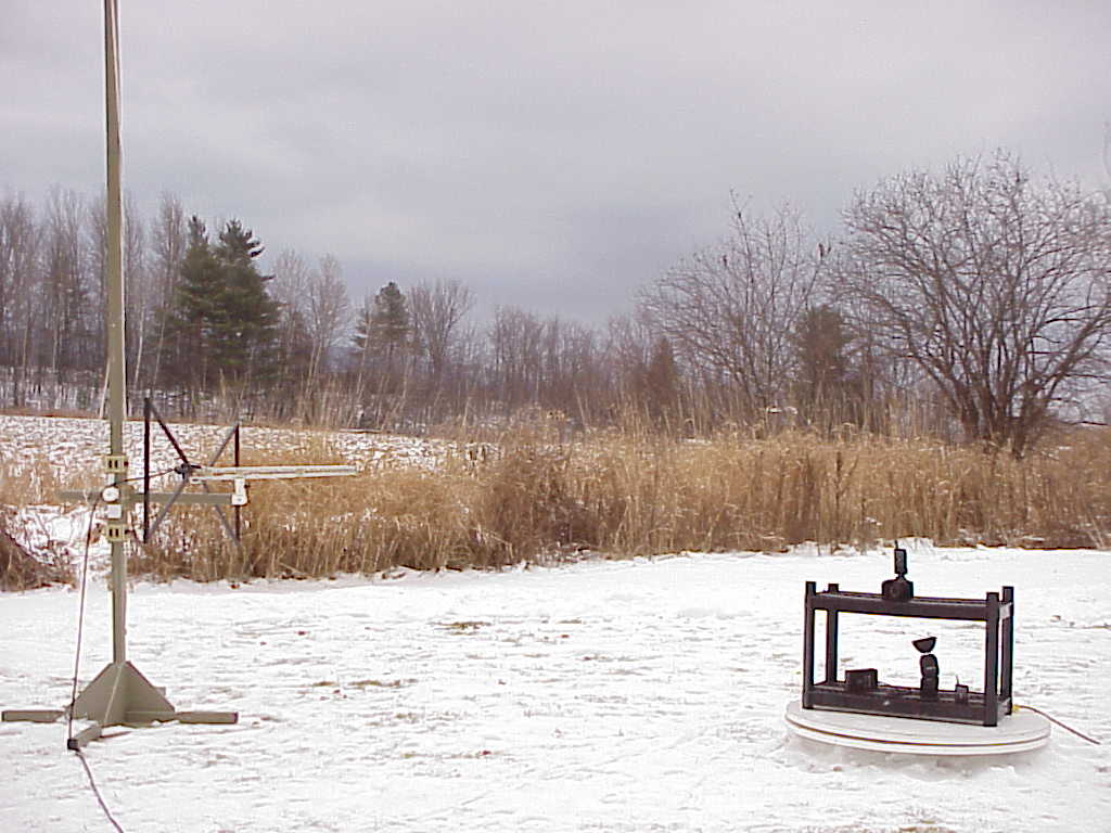
Serial No. GM25002f FCC ID: CEXFW9T FCC TEST REPORT FOR THE QUANTUM INSTRUMENTS, INC. FREEXWIRE PHOTOGRAPHIC DEVICE REMOTE CONTROL TRANSMITTER (FW9T) Prepared for: Quantum Instruments, Inc. 1075 Stewart Ave. Garden City, New York 11530 USA Submitted by: Green Mountain Electromagnetics, Inc. (802) 388-3390 Fax: (802) 388-6279 E-mail: [email protected] 219 Blake Roy Road • Middlebury, Vermont 05753 Copyright: January 18, 2005 This report shall not be reproduced, except in full, without the written approval of GME. QuickTime™ and a GIF decompressor are needed to see this picture. Accredited Cert 898.01 Serial No. GM25002f FCC ID: CEXFW9T 2 of 20 Quantum Instruments, Inc. FCC Tests By Green Mountain Electromagnetics, Inc. Middlebury, Vermont Unit: FreeXWire Photographic Device Remote Control Transmitter (FW9T) Evaluated: December 15, 2004 to January 18, 2005 I. Applicable Standards: The unit described in this report was measured for certification with the Code of Federal Regulations Chapter 47 – "Telecommunication, Part 2 – Frequency Allocations and Radio Treaty Matters: General Rules and Regulations, Subpart J – Equipment Authorization Procedures (2002)." Measurements required were per paragraphs 2.1046 RF Power Output, 2.1047 Modulation Characteristics, 2.1049 Occupied Bandwidth, 2.1051 Spurious Emissions at Antenna Terminals, 2.1053 Field Strength of Spurious Radiation, 2.1055 Frequency Stability, and 2.1093 Radiofrequency Radiation Exposure Evaluation: Portable Devices. The unit was also measured for verification of compliance with "CFR47, Part 15 – Radio Frequency Devices, Subpart C: Intentional Radiators, Paragraph 15.209, Radiated Emissions Limits and Paragraph 15.231, "Periodic operation in the band 40.66 - 40.70 MHz and above 70 MHz." Measurement procedures were in accordance with ANSI C63.4, "Methods of Measurement of Radio-Noise Emissions from Low-Voltage Electrical and Electronic Equipment in the Range of 9 kHz to 40 GHz (2000)," and FCC OET Bulletin 65, "Evaluating Compliance with FCC Guidelines for Human Exposure to Radiofrequency Electromagnetic Fields (August 1997)." Serial No. GM25002f FCC ID: CEXFW9T 3 of 20 II. Unit Tested: The Quantum Instruments, Inc. FW9T transmitter is the portion of the remote control attached to a camera. The FW9T uses DC power and has a 433-MHz crystal oscillator transmitter. It consists of the two-piece plastic enclosure with manual switch hardware, the transmit circuit, the electronics, and the antenna. The table below describes the unit tested to determine compliance with the standards: Model/P/N Manufacturer H/W/D in cm Serial Number FW9T Quantum Instruments, Inc. 10/7/3 ENG001 The highest frequency investigated is ten times the highest fundamental (4.33 GHz). III. Measurement Location: The GME laboratory and Open Area Test Site (OATS) are located at 219 Blake Roy Road, Middlebury, VT. The OATS is a 3-meter site complete with antenna positioner, ground plane and motorized turntable. The OATS is constructed in accordance with ANSI C63.7-1992 and complies with the requirements for radiated emissions testing in ANSI C63.4-2000 and CISPR 16-1993. The electromagnetic laboratory is constructed in accordance with CE immunity standards and ANSI C63.4-2000 (conducted emissions). GME is internationally accredited by the American Association for Laboratory Accreditation (A2LA) and meets the quality requirements in ISO/IEC 17025 (1999), "General Requirements for the Competence of Testing and Calibration Laboratories." Serial No. GM25002f FCC ID: CEXFW9T 4 of 20 IV. Summary of Results: The Quantum Instruments, Inc. FW9T transmitter complies with the requirements in CFR 47, Paragraphs 2 and 15. Section IX contains the results summarized in the table below. CFR 47 Frequency Specified Measured Test Mode/Port Paragraph Range/Level Values Values 1 Output Power Transmit 2.1046 433 MHz 0 dBm (manu. spec.) -2 dBm 2 Modulation Characteristic s Transmit 2.1047 15.231(a) Deactivate time <5 Seconds <5 Seconds 3 Occupied Bandwidth Transmit 2.1049 15.231(c) 20 dB down at 0.25% of Fundamental 1.08 MHz <10 kHz 4 Conducted Spurious Transmit 2.1051 1 MHz to 4.33 GHz >20 dB Attenuation >20 dB Attenuation 5 Frequency Tolerance Transmit 2.1055 Battery End Point 3 V 433.9 MHz 6 Radiated Emissions Enclosur e 15.209 15.231(b) 2.1053 1.705 - 30 MHz 30 - 88 MHz 88 - 216 MHz 216 - 960 MHz 960 - 4339 MHz 433.9 MHz (Fund) Above 434 (Spur) 49.5 dBuV/m 40 dBuV/m 43.5 dBuV/m 46 dBuV/m 54 dBuV/m 81 dBuV/m 61 dB/V/m Within All Limits at 3 Meters 7 Exposure Evaluation Enclosur e 2.1093 433.9 MHz 0.08 W/kg Body 1.6 W/kg 1g Vol Within All Limits Testing was performed by Kyle R. Kowalczyk, president, Green Mountain Electromagnetics and requested by: Quantum Instruments, Inc. 1075 Stewart Ave. Garden City, New York 11530 USA Serial No. GM25002f FCC ID: CEXFW9T 5 of 20 ___________________________ Kyle R. Kowalczyk 1/18/05 Serial No. GM25002f FCC ID: CEXFW9T 6 of 20 V. Measuring Equipment: The table below describes the instrumentation used by Green Mountain Electromagnetics to perform this testing: Unit Manufacturer Model Serial # Last Cal. Next Cal. Spectrum Analyzer Hewlett- Packard 8592 3624A00631 1/13/04 1/30/05 Amplifier Hewlett- Packard 8447 D 2944A07313 5/17/04 5/17/05 Signal Generator Hewlett- Packard E4421B US38220195 10/20/04 10/20/05 Plotter Hewlett- Packard 7475A 2517A05281 n/a n/a Broadband E-field Antenna Antenna Research Associates LPB-2513/A 1125 11/2/04 11/2/05 Serial No. GM25002f FCC ID: CEXFW9T 7 of 20 VI. Equipment and Cable Configuration: GME witnessed the unit in satisfactory condition for testing, however the manufacturer is responsible for ensuring that the equipment under test (EUT) represents the product line. The manufacturer is also responsible for the EMC test plan and for assuring that this report is consistent with that plan. The EUT configuration was arranged to produce maximum radiated emissions as shown in the block diagram below, as well as in the photograph in Se…
Text truncated - open the document above for the full version.
Test Report
Serial No. GM25002f FCC ID: CEXFW9T 13 of 20 IX. Measurement Results for FCC Tests Cont'd: 2. Modulation Characteristics. Programmed for 5-second deactivation. Duty cycle for device shown. Time On = (8 x 15 us) + (10 x 20) usec + 1 x 30 usec + 1 x 40 usec T = .120 msec + 200 msec + .030 msec + 0.040 msec = 0.0039 sec QuickTime™ and a TIFF (Uncompressed) decompressor are needed to see this picture. Serial No. GM25002f FCC ID: CEXFW9T 14 of 20 IX. Measurement Results for FCC Tests Cont'd: 3. Occupied Bandwidth. <1.08 MHz @ 20 dB down QuickTime™ and a TIFF (Uncompressed) decompressor are needed to see this picture. 20 dB limit off h
Test Report
Serial No. GM25002f FCC ID: CEXFW9T IX. Measurement Results for FCC Tests Cont'd: 4. Conducted Spurious. Specification: Attenuation > 20 dB from Fundamental QuickTime™ and a TIFF (Uncompressed) decompressor are needed to see this picture. QuickTime™ and a TIFF (Uncompressed) decompressor are needed to see this picture. Limit Limit Serial No. GM25002f FCC ID: CEXFW9T 15 of 20 IX. Measurement Results for FCC Tests Cont'd: 5. Frequency Stability/Tolerance Cont'd. Frequencies: 433.92 MHz Specification: 3 VDC through battery end (Normal Operation) The table below shows no variation in frequency with selected applied voltage: Voltage (VDC) % Nominal Frequency (MHz) 3.10 Nominal 433.92 3.08 Nominal 433.92 3.06 Nominal 433.92 3.04 Nominal 433.92 3.02 Nominal 433.92 3.00 Nominal 433.92 2.98 Nominal 433.92 2.96 Nominal 433.92 2.94 Nominal 433.92 2.92 Nominal 433.92 2.90 Nominal 433.92 Serial No. GM25002f FCC ID: CEXFW9T 15 of 20 IX. Measurement Results for FCC Tests Cont'd: 6. Radiated Emissions. The table below contains the spectrum analyzer output and the correction factors necessary to apply the limit to the data. Limit Interpolation: 3750 + [(433.9-260)(12500-3750)]/(470-260) = 11,000 uV/m Fundamental Limit Interpolation: 375 + [(433.9-260)(1250-375)]/(470-260) = 1,100 uV/m Spurious Duty Cycle Correction: 20 log (0.0039) = -48 dB for transmitter fundamental and spurious. Field (dBuV/m) = Vmeas (dBuV) + Antenna Factor (dB/m) + Cable Loss (dB) - Amp Gain (dB). Deviation (dB) = Field (dBuV/m) - Limit (dBuV/m); Negative deviation is compliant. Freq Pol RBW VBW VmeasAF Amp CableField Duty Limit Dev MHz H/V kHz kHz dBuV dB1/mdB dB dBuV/m dB dBuV/mdB 1 H 9 9 32 24.2 29 1 28.2 0 49.5 -21.3 1 V 9 9 31 24.2 29 1 27.2 0 49.5 -22.3 10 H 9 9 31 20.1 29 1 23.1 0 49.5 -26.4 10 V 9 9 32 20.1 29 1 24.1 0 49.5 -25.4 30 H 120 300 40 18.6 29 1 30.6 0 40 -9.4 30 V 120 300 39 18.6 29 1 29.6 0 40 -10.4 40 H 120 300 44 18.3 29 1 34.3 0 40 -5.7 40 V 120 300 46 18.3 29 1 36.3 0 40 -3.7 50 H 120 300 39 15.1 29 2 27.1 0 40 -12.9 50 V 120 300 40 15.1 29 2 28.1 0 40 -11.9 60 H 120 300 50 11.1 29 2 34.1 0 40 -5.9 60 V 120 300 47 11.1 29 2 31.1 0 40 -8.9 70 H 120 300 53 8.1 29 2 34.1 0 40 -5.9 70 V 120 300 51 8.1 29 2 32.1 0 40 -7.9 80 H 120 300 52 9.8 29 2 34.8 0 40 -5.2 80 V 120 300 44 9.8 29 2 26.8 0 40 -13.2 90 H 120 300 45 10.9 29 2 28.9 0 43.5 -14.6 90 V 120 300 41 10.9 29 2 24.9 0 43.5 -18.6 100 H 120 300 43.5 12.2 29 3 29.7 0 43.5 -13.8 100 V 120 300 43 12.2 29 3 29.2 0 43.5 -14.3 Serial No. GM25002f FCC ID: CEXFW9T 15 of 20 Table 1 – Corrected Radiated Emissions Data and FCC Limit Serial No. GM25002f FCC ID: CEXFW9T 15 of 20 IX. Measurement Results for FCC Tests Cont'd: 6. Radiated Emissions Cont'd. The table below contains the spectrum analyzer output and the correction factors necessary to apply the limit to the data. Freq Pol RBW VBW VmeasAF Amp CableField Duty Limit Dev MHz H/V kHz kHz dBuV dB1/mdB dB dBuV/m dB dBuV/mdB 125 H 120 300 43.5 12.9 29 3 30.4 0 43.5 -13.1 125 V 120 300 42 12.9 29 3 28.9 0 43.5 -14.6 150 H 120 300 43.5 11.1 29 4 29.6 0 43.5 -13.9 150 V 120 300 43 11.1 29 4 29.1 0 43.5 -14.4 175 H 120 300 44 10.9 29 4 29.9 0 43.5 -13.6 175 V 120 300 45 10.9 29 4 30.9 0 43.5 -12.6 200 H 120 300 46 11.3 29 4 32.3 0 43.5 -11.2 200 V 120 300 43 11.3 29 4 29.3 0 43.5 -14.2 250 H 120 300 38 13.4 29 4 26.4 0 46 -19.6 250 V 120 300 39 13.4 29 4 27.4 0 46 -18.6 300 H 120 300 41 14.9 28 4 31.9 0 46 -14.1 300 H 120 300 41 14.9 28 4 31.9 0 46 -14.1 433 H 120 300 95 16.1 28 5 88.1 48 80.8 -40.7 433 V 120 300 95 16.1 28 5 88.1 48 80.8 -40.7 500 H 120 300 46 18.6 28 5 41.6 0 46 -4.4 500 V 120 300 45 18.6 28 5 40.6 0 46 -5.4 600 H 120 300 40 19.7 28 5 36.7 0 46 -9.3 600 V 120 300 43 19.7 28 5 39.7 0 46 -6.3 700 H 120 300 44 20.2 28 5.5 41.7 0 46 -4.3 700 V 120 300 43 20.2 28 5.5 40.7 0 46 -5.3 800 H 120 300 38 21.5 28 6 37.5 0 46 -8.5 800 V 120 300 39 21.5 28 6 38.5 0 46 -7.5 866 H 120 300 68 21.5 28 6 67.5 48 46 -26.5 866 V 120 300 69 21.5 28 6 68.5 48 46 -25.5 Serial No. GM25002f FCC ID: CEXFW9T 15 of 20 Table 1 Cont'd – Corrected Radiated Emissions Data and FCC Limit Serial No. GM25002f FCC ID: CEXFW9T 15 of 20 IX. Measurement Results for FCC Tests Cont'd: 6. Radiated Emissions Cont'd. The table below contains the spectrum analyzer output and the correction factors necessary to apply the limit to the data. Freq Pol RBW VBW VmeasAF Amp CableField Duty Limit Dev MHz H/V kHz kHz dBuV dB1/mdB dB dBuV/m dB dBuV/mdB 959 H 120 300 37 22.4 27 7 39.4 0 46 -6.6 959 V 120 300 39 22.4 27 7 41.4 0 46 -4.6 960 H 120 300 38 22.4 27 7 40.4 0 46 -5.6 960 V 120 300 37 22.4 27 7 39.4 0 46 -6.6 1000 H 1000 1000 34 24.2 27 8 39.2 0 54 -14.8 1000 V 1000 1000 32 24.2 27 8 37.2 0 54 -16.8 1299 H 1000 1000 76 24.8 26 9 83.8 48 61 -25.2 1299 V 1000 1000 75 24.8 26 9 82.8 48 61 -26.2 1732 H 1000 1000 73 26.1 24 12 87.1 48 61 -21.9 1732 V 1000 1000 73 26.1 24 12 87.1 48 61 -21.9 2165 H 1000 1000 59 26.1 24 12 73.1 48 61 -35.9 2165 V 1000 1000 58 26.1 24 12 72.1 48 61 -36.9 2598 H 1000 1000 47 28.2 23 1 53.2 48 61 -55.8 2598 V 1000 1000 47 28.2 23 1 53.2 48 61 -55.8 3031 H 1000 1000 32 28.2 23 1 38.2 48 61 -70.8 3031 V 1000 1000 34 28.2 23 1 40.2 48 61 -68.8 3464 H 1000 1000 35 28.2 23 1 41.2 48 61 -67.8 3464 V 1000 1000 32 28.2 23 1 38.2 48 61 -70.8 3897 H 1000 1000 33 32.4 23 2 44.4 48 61 -64.6 3897 V 1000 1000 34 32.4 23 2 45.4 48 61 -63.6 4339 H 1000 1000 35 32.8 23 3 47.8 48 61 -61.2 4339 V 1000 1000 31 32.8 23 3 43.8 48 61 -65.2 Table 1 Cont'd – Corrected Radiated Emissions Data and FCC Limit Serial No. GM25002f FCC ID: CEXFW9T 15 of 20 IX. Measurement Results for FCC Tests Cont'd: 7. Exposure Evaluation. The analysis below compares the measured power to the maximum permissible exposure limit for general population with uncontrolled access. The unit can be used continuously; no special averaging time or limit relaxations are employed. Maximum peak available power is used in calculations. Unit Frequency: 433.9 MHz Unit Maximum Average Powe…
Text truncated - open the document above for the full version.
Contact Information
Applicant
Richard Shaper
Technical Contact
Green Moutain ElectromagneticsKyle Kowalczyk
[email protected]802-388-3390
219 Blake Roy Road · Middlebury, Vermont · United States
Non-Technical Contact
Green Moutain ElectromagneticsKyle Kowalczyk
[email protected]802-388-3390
Test Firm
Green Mountain ElectromagneticsKyle Kowalczyk
Technical Specifications
| # | Rule Parts | Frequency Range | Power Output |
|---|---|---|---|
| 1 | 15.231 | 433.9 MHz - 433.9 MHz | - |
Other Applications from Quantum Instruments Inc
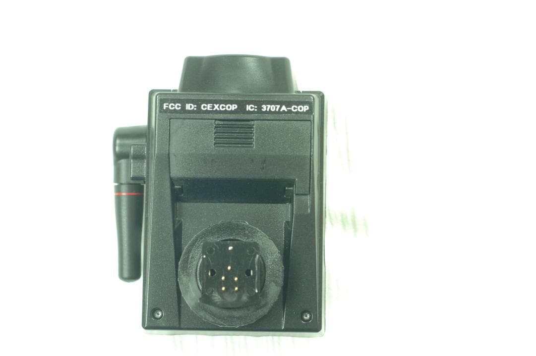
CEXCOP
Jun 05, 2012A Wireless Radio Commander Unit for Digital Cameras to Control Remote Flashes
Equipment Class
DSC - Part 15 Security/Remote Control Transmitter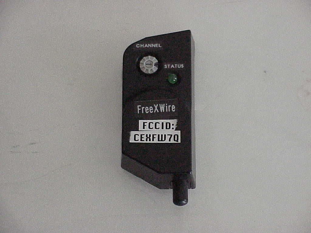
CEXFW7Q
Mar 07, 2005Wireless Flash for Camera
Equipment Class
CYY - Communications Receiver used w/Pt 15 Transmitter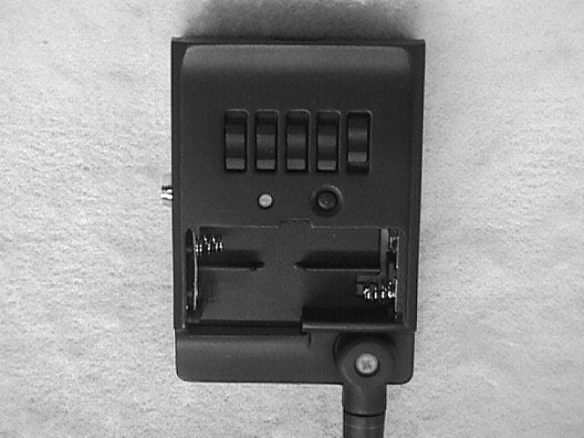
CEXFW10
Oct 23, 2000Camera Remote Control
Equipment Class
DSC - Part 15 Security/Remote Control TransmitterCEX8EH-505S
Oct 21, 1990DSC - Part 15 Security/Remote Control Transmitter
Equipment Class
DSC - Part 15 Security/Remote Control TransmitterCEX8EH-505R
Feb 25, 1990CRR - Superregenerative Receiver
Equipment Class
CRR - Superregenerative Receiver