CEXFW7QWireless Flash for Camera
Quantum Instruments Inc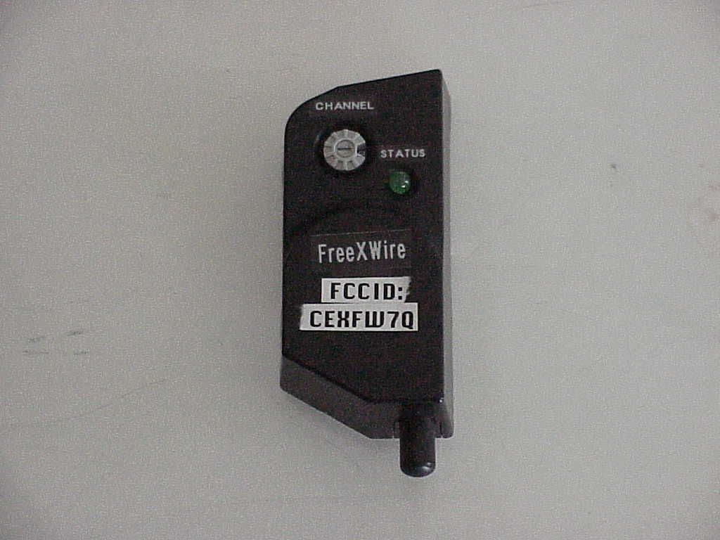
Click to zoom
Application Details
- Equipment Class
- CYY - Communications Receiver used w/Pt 15 Transmitter
- Date of Grant
- Mar 07, 2005
- Application Purpose
- Original Equipment
- Date of Application
- Jan 10, 2005
- Equipment Note
- Wireless Flash for Camera
- Frequency Range
- 433.90000000 - 433.90000000
- Company
- Quantum Instruments Inc
- Country
- United States
Documents & Files
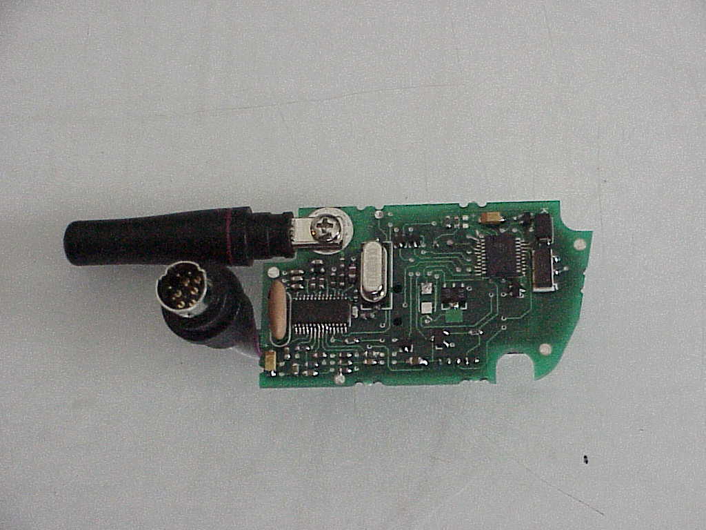
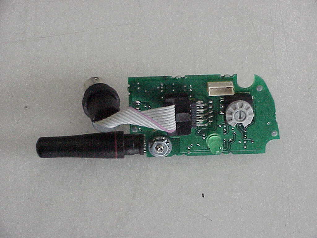
Document Text
Text extracted from the exhibit documents filed with the FCC. Open a document above to read the original.
Users Manual
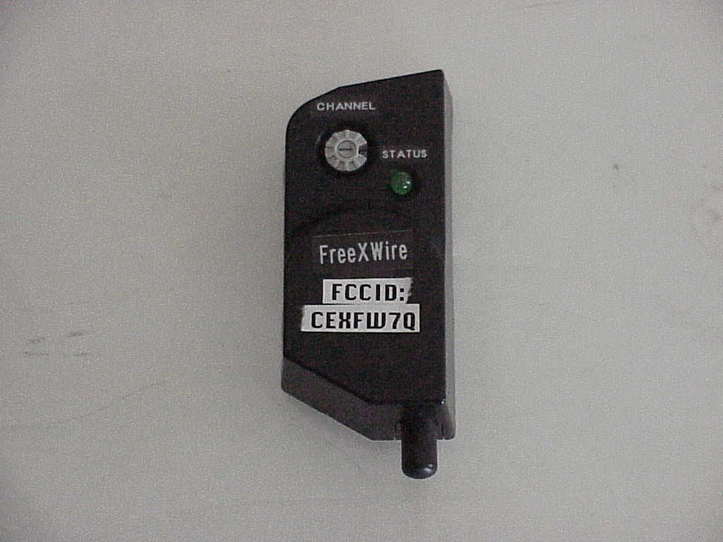
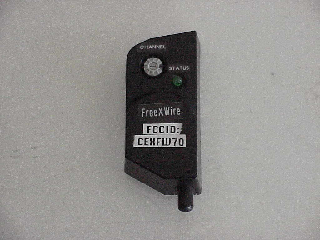
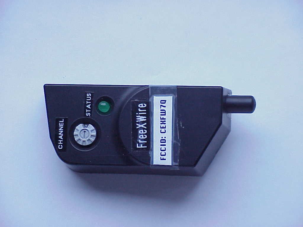
Instructions FreeXwire model FW7Q Remote Operation/Digital Wireless TTL for Qflash 4d/5d Quantum Instruments Inc. FreeXwire model FW7Q is a dedicated receiver for Qflash models T4d, X4d, T5d, and X5d. It is compatible with FreeXwire Transmitter FW9T and Transceiver FW10 and provides remote operation and digital wireless TTL for Qflash series 4d/5d 1. Mounting FreeXwire FW7Q Turn off Qflash power before mounting the FW7Q. FW7Q plugs into the lower Accessory socket of Qflash, as shown in the diagram. [diagram 1] For added stability a hook-and- loop pad is mounted on the back of Receiver FW7Q. One part of this pad will be attached to the Qflash housing as follows: Note where the hook and loop pad will come into contact with the Qflash housing when FW7Q is plugged into the lower Accessory socket. Clean the area of any dirt or grease. Remove the adhesive liner from the pad (without touching the adhesive), and align and mount FW7Q. Then press the FW7Q housing firmly against Qflash so that the hook and loop pad adheres to the Qflash housing. You can now remove and re-mount FW7Q when you need to use it. Additional hook and loop pads are included with FW7Q. They can be used to place additional pads on other Qflash units, or as a replacement. 2. Powering FW7Q Qflash series 4d/5d powers the FreeXwire FW7Q. When Qflash is powered, the green LED indicator on the FW7Q should blink once per second. 3. Setting the Channel Code The Channel Codes allow FreeXwire’s to work together. Set the same Channel Code as your transmitter unit FW8 or FW10 (FW10 should be set as TX). Rotate the dial to the desired Code, 0 through 7. To rotate, press the pad of your thumb on the dial and turn. Or, use a small screwdriver. Channels can be matched by number or by the position of the cutout in the Channel dial. 4. Setting the Zone Code The FreeXwire FW7Q has no Zone Code Switch. When used with a Qflash 4d, FW7Q will activate for any Zone 1, 2, 3, or 4, on the matching Channel. However, Qflash 5d can set the Zone Code of FW7Q through its control panel. (Note: Qflash 4d models can be upgraded to Qflash 5d models. Please contact the Service Department @ Quantum). To set the Zone on a Qflash 5d, press the Option button three times. The Zone Code settings should display on Qflash screen. Use the Set button select a Zone, then press the Up S and Down T buttons to turn the selected Zone on or off. 5. Qflash T4 Remote Control Operation The Remote mode allows a “Control” Qflash to remotely set the functions of “Remote” Qflash units linked by the FreeXwire system. A full explanation of the Wireless Control mode appears in the Qflash manual under Multiple Qflash Operation - Wireless Mode. Set Qflash 4d/5d to Remote Mode by pressing the Mode button. You can select to set Qflash as Remote 1 or Remote 2. If you have two remote units, set one unit for Remote 1 and the other unit for Remote 2. Now the “Control” Qflash (which is connected to an FW9T or FW10) controls the operating mode and settings of Remote unit(s). See Qflash instructions for details. 6. Digital Wireless TTL Operation Set Qflash 5d to Remote Mode as describe in Section 5. The Remote unit will receive digital wireless TTL signal from Control unit. No further setting is required. This mode is compatible with digital camera pre-flash TTL, as well as film camera TTL exposure control. Qflash 4d units need to be upgraded to Qflash 5d models for this function. 7. Range selection The range of FW7Q receiver is set to NORMAL by default which provides a range up to 200’ (70m). This setting is recommended for general needs and for digital wireless. If the operation range is more than 200’ (usually for wireless shutter, up to 500’), set RANGE to HI. This can be set via the Qflash 5d “Options”. If using a Qflash 4d, the range setting will be NORMAL only. 8. Specifications Size: 3 X 1.5 X 1 in (8 x 3.5 x 2.5 cm) Weight: 1.3 oz (37g) Maximum Range: varies with local conditions – up to 400’ (120m) with FW10 or up to 500’(150m) with FW9 Maximum flash rate: 25fps Maximum sync delay from camera trigger to remote flash: 1/2000 sec Maximum camera Shutter speeds: Leaf shutters: 1/500 Focal plane shutter: 1/250 [logo] FCC Tested to comply with FCC standards CANADA: FCC ID: CEXFW7Q FreeXwire model FW7Q This device complies with Part 15 of the FCC Rules and with RSS-210 of Industry & Science Canada. Operation is subject to the following conditions: 1) this device may not cause harmful interference, and 2) this device must accept any interference received including that which may cause undesired operation of the device. IMPORTANT - CAUTION Changes or modifications to this equipment could void your authority to use this product under the equipment authorization granted by the regulating agencies. [logo] Declaration of Conformity: Quantum Instruments, Inc. declares that FreeWire FW10 satisfies all the technical regulations applicable to the product within the scope of Council Directive 1999/5/EC. For Customer Service, technical help, or information: Quantum Instruments Inc 1075 Stewart Ave. Garden City NY 11530 USA PH: 1-516-222-6000 FAX: 1-516-222-0569 Web: www.qtm.com Email: [email protected]
Block Diagram
Fig 1. FW7Q and FW8R Circuit Block Diagram RF Receiver 433.92MHZ Micro- Controller 8MHZ Driver Circuit DC-DC Converter Selector Switches
Cover Letter(s)
Green Mountain Electromagnetics, Inc. GME (802)388-3390 Fax: (802)388-6279 Email: [email protected] 219 Blake Roy Road • Middlebury, VT 05753 3/3/05 Attn: Andy Leimer FCC 7435 Oakland Mills Road Columbia, MD 21046 Re: Confidentiality for FCC ID's CEXFW7Q, CEXFW8R and CEXFW9T This letter serves as an official request for confidentiality under FCC Rule 0.459. we have requested that the schematics required to be submitted with this application be witheld from public review. The documents contain company proprietary information that was developed exclusively at private expense for: Quantum Instruments, Inc. 1075 Stewart Ave. Garden City, NY 11530 Please call if you have any questions. Sincerely, Kyle R. Kowalczyk Agent/President
Test Report
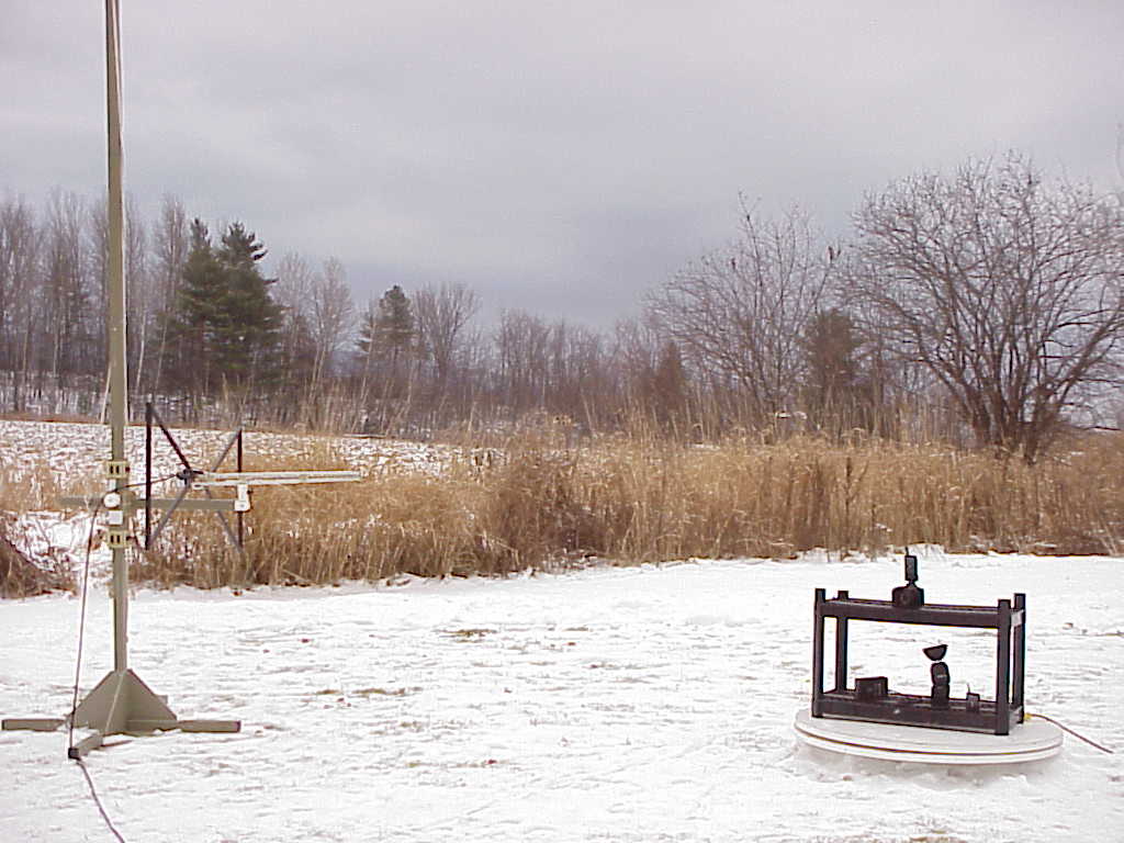
Serial No. GM25004f FCC ID: CEXFW8R FCC ID: CEXFW7Q FCC TEST REPORT FOR THE QUANTUM INSTRUMENTS, INC. FREEXWIRE PHOTOGRAPHIC DEVICE REMOTE CONTROL RECEIVERS (FW7Q/FW8R) Prepared for: Quantum Instruments, Inc. 1075 Stewart Ave. Garden City, New York 11530 USA Submitted by: Green Mountain Electromagnetics, Inc. (802) 388-3390 Fax: (802) 388-6279 E-mail: [email protected] 219 Blake Roy Road • Middlebury, Vermont 05753 Copyright: January 18, 2005 This report shall not be reproduced, except in full, without the written approval of GME. QuickTime™ and a GIF decompressor are needed to see this picture. Accredited Cert 898.01 Serial No. GM25002f FCC ID: CEXFW8R FCC ID: CEXFW7Q 2 of 12 Quantum Instruments, Inc. FCC Tests By Green Mountain Electromagnetics, Inc. Middlebury, Vermont Unit: FreeXWire Photographic Device Remote Control Receivers (FW7Q & FW8R) Evaluated: December 15, 2004 to January 18, 2005 I. Applicable Standards: The unit described in this report was measured for certification with the Code of Federal Regulations Chapter 47 – "Telecommunication, Part 2 – Frequency Allocations and Radio Treaty Matters: General Rules and Regulations, Subpart J – Equipment Authorization Procedures (2002)." Measurements required were per paragraphs, 2.1051 Spurious Emissions at Antenna Terminals, and 2.1053 Field Strength of Spurious Radiation. The unit was also measured for verification of compliance with "CFR47, Part 15 – Radio Frequency Devices, Subpart C: Intentional Radiators, Paragraph 15.209, Radiated Emissions Limits." Measurement procedures were in accordance with ANSI C63.4, "Methods of Measurement of Radio-Noise Emissions from Low-Voltage Electrical and Electronic Equipment in the Range of 9 kHz to 40 GHz (2000)." Serial No. GM25002f FCC ID: CEXFW8R FCC ID: CEXFW7Q 3 of 12 II. Unit Tested: The Quantum Instruments, Inc. FW7Q and FW8R receivers are the portion of the remote control attached to a flash unit. The FW7Q and FW8R use DC power and have a 433-MHz receiver. It consists of the two-piece plastic enclosure with manual switch hardware, the transmit circuit, the electronics, and the antenna. The FW7Q is directly attached to the flash unit and the FW8R is cabled. The table below describes the units tested to determine compliance with the standards: Model/P/N Manufacturer H/W/D in cm Serial Number FW8R Quantum Instruments, Inc. 10/7/3 ENG001 FW7Q Quantum Instruments, Inc. 10/7/3 ENG001 The highest frequency investigated is ten times the highest fundamental (4.33 GHz). III. Measurement Location: The GME laboratory and Open Area Test Site (OATS) are located at 219 Blake Roy Road, Middlebury, VT. The OATS is a 3-meter site complete with antenna positioner, ground plane and motorized turntable. The OATS is constructed in accordance with ANSI C63.7-1992 and complies with the requirements for radiated emissions testing in ANSI C63.4-2000 and CISPR 16-1993. The electromagnetic laboratory is constructed in accordance with CE immunity standards and ANSI C63.4-2000 (conducted emissions). GME is internationally accredited by the American Association for Laboratory Accreditation (A2LA) and meets the quality requirements in ISO/IEC 17025 (1999), "General Requirements for the Competence of Testing and Calibration Laboratories." Serial No. GM25002f FCC ID: CEXFW8R FCC ID: CEXFW7Q 4 of 12 IV. Summary of Results: The Quantum Instruments, Inc. FW7Q and FW8R receivers comply with the requirements in CFR 47, Paragraphs 2 and 15. Section IX contains the results summarized in the table below. CFR 47 Frequency Specified Measured Test Mode/Port Paragraph Range/Level Values Values 1 Conducted Spurious Transmit 2.1051 1 MHz to 4.33 GHz >20 dB Attenuation >20 dB Attenuation 2 Radiated Emissions Enclosur e 15.209 2.1053 1.705 - 30 MHz 30 - 88 MHz 88 - 216 MHz 216 - 960 MHz 960 - 4339 MHz 49.5 dBuV/m 40 dBuV/m 43.5 dBuV/m 46 dBuV/m 54 dBuV/m Within All Limits at 3 Meters Testing was performed by Kyle R. Kowalczyk, president, Green Mountain Electromagnetics and requested by: Quantum Instruments, Inc. 1075 Stewart Ave. Garden City, New York 11530 USA ___________________________ Kyle R. Kowalczyk 1/18/05 Serial No. GM25002f FCC ID: CEXFW8R FCC ID: CEXFW7Q 5 of 12 V. Measuring Equipment: The table below describes the instrumentation used by Green Mountain Electromagnetics to perform this testing: Unit Manufacturer Model Serial # Last Cal. Next Cal. Spectrum Analyzer Hewlett- Packard 8592 3624A00631 1/13/04 1/30/05 Amplifier Hewlett- Packard 8447 D 2944A07313 5/17/04 5/17/05 Signal Generator Hewlett- Packard E4421B US38220195 10/20/04 10/20/05 Plotter Hewlett- Packard 7475A 2517A05281 n/a n/a Broadband E-field Antenna Antenna Research Associates LPB-2513/A 1125 11/2/04 11/2/05 Serial No. GM25002f FCC ID: CEXFW8R FCC ID: CEXFW7Q 6 of 12 VI. Equipment and Cable Configuration: GME witnessed the unit in satisfactory condition for testing, however the manufacturer is responsible for ensuring that the equipment under test (EUT) represents the product line. The manufacturer is also responsible for the EMC test plan and for assuring that this report is consistent with that plan. The EUT configuration was arranged to produce maximum radiated emissions as shown in the block diagram below, as well as in the photograph in Section VIII. The equipment was subjected to complete emissions tests. Figure 1 – Block Diagram of EUT on Turntable The EUT was operating in a continuous mode utilizing and testing its remote control functions. The EUT was also set to self-test upon power up. Transmitter attached to Camera Receiver on Flash Serial No. GM25002f FCC ID: CEXFW8R FCC ID: CEXFW7Q 7 of 12 VII. Measurement Procedures for FCC Tests: 1. Conducted Spurious. Specification: Attenuation >20 dB a. Set up EUT and test instrumentation in laboratory. i. Connect EUT to battery power and operate companion unit. b. Verify spectrum analyzer and EUT operation. i. Use internal spectrum analyzer attenuator. c. Verify EUT frequency with non-contact probe and sp…
Text truncated - open the document above for the full version.
Contact Information
Applicant
Richard Shaper
Technical Contact
Quantum InstrumentsKowalczyk Kowalczyk
[email protected]802-388-3390
219 Blake Roy Road · Middlebury, Vermont · United States
Non-Technical Contact
Green Moutain ElectromagneticsKowalczyk Kowalczyk
[email protected]802-388-3390
Test Firm
Green Mountain ElectromagneticsKyle Kowalczyk
Technical Specifications
| # | Rule Parts | Frequency Range | Power Output |
|---|---|---|---|
| 1 | 15B | 433.9 MHz - 433.9 MHz | - |
Other Applications from Quantum Instruments Inc
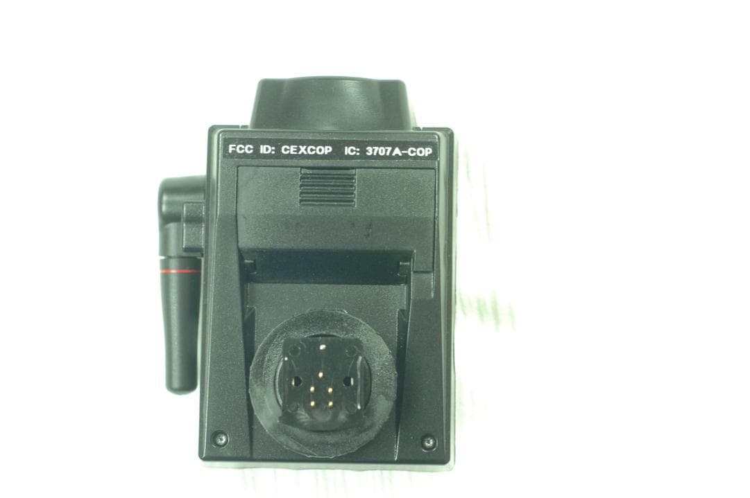
CEXCOP
Jun 05, 2012A Wireless Radio Commander Unit for Digital Cameras to Control Remote Flashes
Equipment Class
DSC - Part 15 Security/Remote Control Transmitter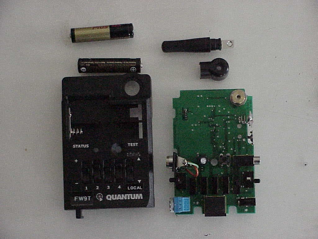
CEXFW9T
Mar 07, 2005Wireless Flash for Camera
Equipment Class
DSC - Part 15 Security/Remote Control Transmitter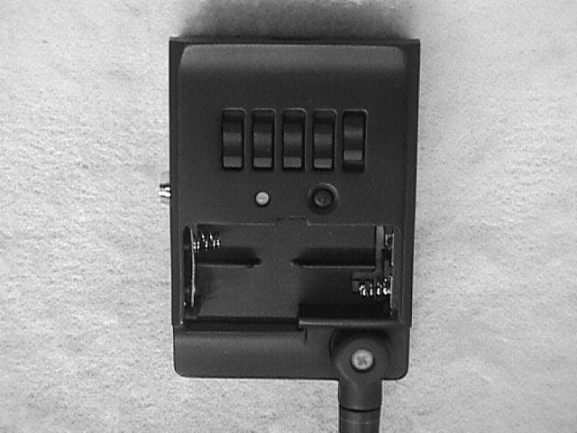
CEXFW10
Oct 23, 2000Camera Remote Control
Equipment Class
DSC - Part 15 Security/Remote Control TransmitterCEX8EH-505S
Oct 21, 1990DSC - Part 15 Security/Remote Control Transmitter
Equipment Class
DSC - Part 15 Security/Remote Control TransmitterCEX8EH-505R
Feb 25, 1990CRR - Superregenerative Receiver
Equipment Class
CRR - Superregenerative Receiver