CFS-2CHRFRCVRReceiver
Ademco Inc.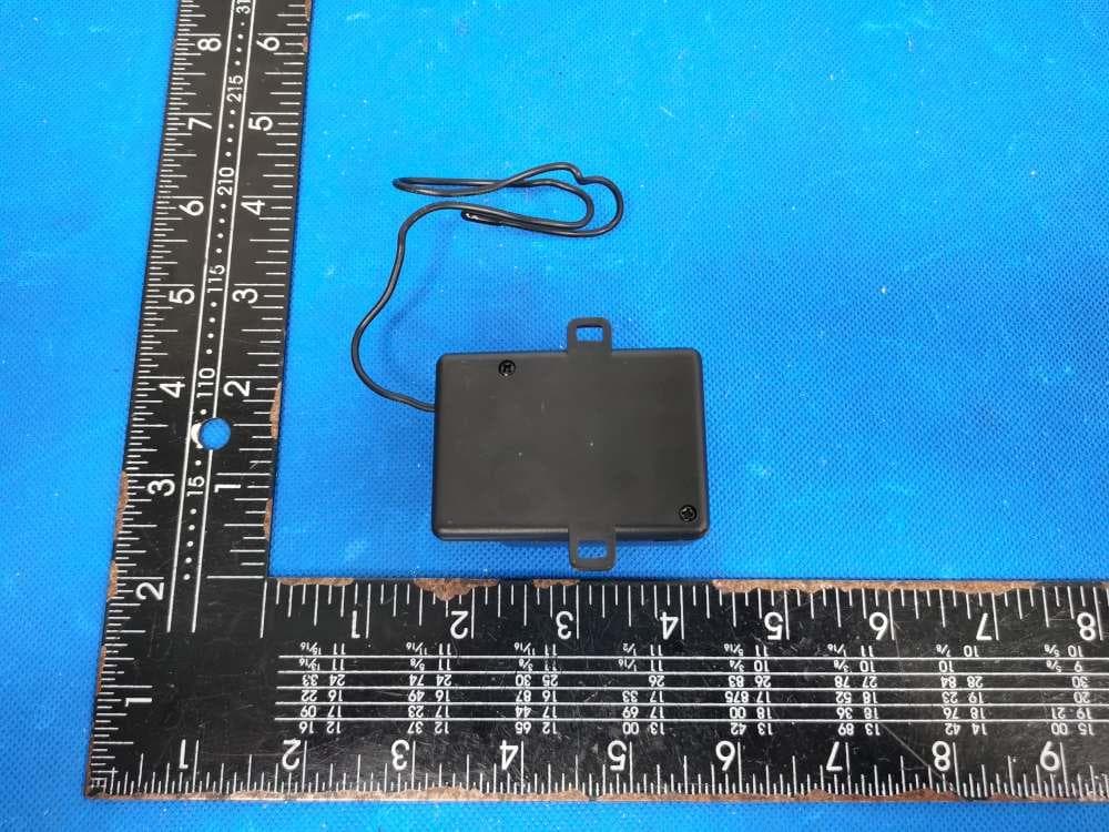
Click to zoom
Application Details
- Equipment Class
- CYY - Communications Receiver used w/Pt 15 Transmitter
- Date of Grant
- Nov 19, 2022
- Application Purpose
- Original Equipment
- Date of Application
- Nov 17, 2022
- Equipment Note
- Receiver
- Frequency Range
- 315.00000000 - 315.00000000
- Company
- Ademco Inc.
- Country
- United States
Documents & Files
Document Text
Text extracted from the exhibit documents filed with the FCC. Open a document above to read the original.
Users Manual
wboxtech.com FOR MORE INFORMATION, CONTACT YOUR ADI SALES PERSON Installation & Operation Guide One and Two-channel RF Receiver Main Features: Pairing a New Transmitter to the Receiver/Code Learning: 1. Connect the two power supply wires, one to VDD and the other GND. 2. When the power is initiated, the LED will light for 1 second and the receiver is ready for learning. 3. Adding New code into Channel 1: Press LEARN BUTTON once, the LED will light for 1 second, go off for 1 second and then light again. Press any button on the Transmitter; if the code is learned successfully, the LED will blink; then release the button on the remote, the LED will be OFF. If the remote cannot read the signal, the LED will light for 10 seconds and finish its learning status. 4. Adding New code into Channel 2: Press LEARN BUTTON twice, the LED will light for 1 second, go off for 1 second and then light again. Press any button on the remote; if the code is learned successfully, the LED will blink; then release the button on the remote, the LED will be OFF. If the remote cannot read the signal, the LED will light for 10 seconds and finish its learning status. 2-CH Receiver shown LEARN BUTTON: for pairing transmitter with receiver or to remove the transmitter. Press once: for CH1 Press twice: for CH2 WBox Part #s: 0E-1CHRFRCVR & 0E-2CHRFRCVR • Five relay output programming functions; each channel can be independently programmed to operate in a different function • Compatibility: Rolling code and fixed code • Operating Temperature: -14 to 140°F ( -25 to 60 °C ) • Capacity to learn up to 200 codes • Power supply: 12-24 VDC / VAC • Frequency: 315MHz • Relay Contact Rating: Dry Form "C", 10amp. Max. per channel wboxtech.com FOR MORE INFORMATION, CONTACT YOUR ADI SALES PERSON Installation & Operation Guide Deleting code from the receiver: Programming Channel Relay Output Modes: Deleting all codes: Press LEARN BUTTON for 8 seconds or until the LED lights, release the button and the LED will go off, all codes will have been deleted. Each channel can be independently programmed to operate in a different function. 1. Hold the PROGRAM BUTTON 1 or 2 for 3 or more seconds. The LED on the receiver will flash number of times equal to the output mode that it is in. (for example, if it flashes 2 times, it means we are set to Toggle mode). 2. To change a relay output mode, press the program button, each press moves to the next mode in the sequence shown in table 1. 3. After select the mode, count the number of LED flashes times to verify the channel is set to the correct mode. 4. To exit programming, hold the PROGRAM BUTTON 1 & 2 for 3 seconds or wait 15 seconds. Table 1: Press Program Button N times Default 2 3 4 5 1 2 3 4 5 4-Sec Timed Mode, Auto. OFF Toggle Mode Latch Mode Validity Mode 1 Second Timed Mode Times of LED FlashingOutput Mode 4-Second Timed Mode (default): When transmitter button is pressed, the relay will turn ON for 4s, then auto. OFF Toggle Mode: When the transmitter button is pressed once and released, the relay will turn ON, then one needs to press the transmitter button again, for the relay to turns OFF. Latch Mode: Press the transmitter button once, and the replay turns ON and stays ON. The relay will remain ON regardless of whether a compatible transmitter button is pressed again or not. To turn the relay OFF, press the LEARN BUTTON on the receiver once to reset. Validity Mode: The relay is ON for as long as the transmitter buttons is pressed. 1-Second Timed Mode: When the transmitter button is pressed, the relay will turn ON for 1s & then auto. OFF. Repeat above steps for Channel 2. (If your receiver has 2 channels) Notes California Proposition 65 Warning: These products do not contain chemicals which are known to the State of California to cause cancer and birth defects or other reproductive harm. wboxtech.com FOR MORE INFORMATION, CONTACT YOUR ADI SALES PERSON Installation & Operation Guide Diagram of the receiver: NOCMNCNOCMNCVDDGNDANT P2P1 CH2CH1 LED LEARN CH2 relayCH1 relay (if your receiver has 2 channels) + - Power input PROGRAM BUTTONS: P1 button for Channel 1 programming P2 button for Channel 2 programming THIS DEVICE COMPLIES WITH PART 15 OF THE FCC RULES. OPERATION IS SUBJECT TO THE FOLLOWING TWO CONDITIONS: (1). THIS DEVICE MAY NOT CAUSE HARMFUL INTERFERENCE AND (2). THIS DEVICE MUST ACCEPT ANY INTERFERENCE RECEIVED INCLUDING INTERFERENCE THAT MAY CAUSE UNDESIRED OPERATION. wboxtech.com FOR MORE INFORMATION, CONTACT YOUR ADI SALES PERSON Installation & Operation Guide FCC/IC COMPLIANCE STATEMENTS Warranty Notice: The changes or modifications not expressly approved by the party responsible for compliance could void the user’s authority to operate the equipment. IMPORTANT NOTE: To comply with the FCC RF exposure compliance requirements, no change to the antenna or the device is permitted. Any change to the antenna or the device could result in the device exceeding the RF exposure requirements and void user’s authority to operate the device. This device complies with Industry Canada license-exempt RSS standard(s). Operation is subject to the following two conditions: (1) this device may not cause interference, and (2) this device must accept any interference, including interference that may cause undesired operation of the device. One Year Warranty This product is covered by a 1-year limited warranty from the date of its original purchase. Fully compatible W Box transmitters offered with One or Two-channel RF Receivers * 315 MHz, Rolling code * Battery storage life - Min. 2 years 0E-2C2BPTRAN 0E-2C2BHTRAN 0E-4C4BHTRAN 2x3vdc coin CR2016 Li batteries 1x12vdc cylindrical Alkaline battery 1x12vdc cylindrical Alkaline battery 2-channel 2-Button Pendant Transmitter 2-channel 2-Button Handheld Transmitter 4-channel 4-Button Handheld Transmitter wboxtech.com FOR MORE INFORMATION, CONTACT YOUR ADI SALES PERSON GUIDE D’INSTALLATION ET D’UTILISATION One and Two-channel RF Receiver Caractéristiques princi…
Text truncated - open the document above for the full version.
Attestation Statements
Ademco Inc. Model Difference Product Name: Receiver Model Number: 0E-2CHRFRCVR, 0E-1CHRFRCVR FCC Identifier: CFS-2CHRFRCVR All the models are the same circuit and RF module, except the model names and Appearance Port. Regards Sincerely Client’s signature Client’s name / title : Christian Fouth / Sr. Wireless Certification Engineer Contact information / address: 2 Corporate Center Drive Suite 100 Melville, NY 11747
Cover Letter(s)
Ademco Inc. 1/1 Letter of Authorization Company: Ademco Inc. Address: 2 Corporate Center Drive Suite 100 Melville, NY 11747 Product Name: Receiver Model Number: 0E-2CHRFRCVR, 0E-1CHRFRCVR FCC Identifier: CFS-2CHRFRCVR We authorize LGAI Technological Center S.A., Ronda de la Font del Carme, s/n, 08193 Bellaterra, Spain, to act on our behalf on all matters concerning the above named equipment. Any individual within LGAI Technological Center S.A. is authorized to act on our behalf and take action on the application. We declare that authorize LGAI Technological Center S.A., Ronda de la Font del Carme, s/n, 08193 Bellaterra, Spain, is allowed to forward all information related to the approval project to the Federal Communication Commission and to discuss any issues concerning the approval application. Any and all acts carried out by LGAI Technological Center S.A. on our behalf shall have the same effect as acts of our own. Name: Christian Fouth Date: 2022-11-15 Title: Sr. Wireless Certification Engineer Signature of applicant:
Cover Letter(s)
Ademco Inc. 1/1 Office of Engineering Technology Federal Communications Commission 7435 Oakland Mills Road Columbia, MD 21046 Date: 2022-11-15 Subject: Request for Confidentiality FCC ID: CFS-2CHRFRCVR To Whom It May Concern, Pursuant to the provisions of Sections 0.457 and 0.459 of Commission's rules (47CFR0.457, 0.459), we are requesting the Commission to withhold the following attachment(s) as confidential document from public disclosure. Exhibits Long-Term Confidentiality Short-Term Confidentiality NOTE 2 ID Label/Location No No Attestation Statement No No External Photos No ☐ Block Diagram ☒ ☐ Schematics ☒ ☐ Test Report No No Test Setup Photos No ☐ User’s Manual No ☐ Internal Photos No ☐ Parts List / Tune Up ☐ ☐ RF Exposure Info No No Operational Description ☒ ☐ Cover Letter(s) No No SDR Software / Security Info ☐ No NOTE 1: Long-Term Confidentiality may be permitted under special conditions (See II. LONG-TERM CONFIDENTIALITY, Section 3 of KDB 726920, use last in force) NOTE 2: Short-Term Confidentiality can be requested for a maximum of 180 days from the date of the grant. Above mentioned document contains detailed system and equipment description are considered as proprietary information in operation of the equipment. The public disclosure of above documents might be harmful to our company and would give competitor an unfair advantage in the market. It is our understanding that all measurement test reports, FCC ID label format and correspondent during certification review process cannot be granted as confidential documents and those information will be available for public review once the grant of equipment authorization is issued. Sincerely, Signature: Name: Christian Fouth Title: Sr. Wireless Certification Engineer
External Photos
ANT
ID Label/Location Info
Size:16*10mm M/N: 0E-2CHRFRCVR FCC ID: CFS-2CHRFRCVR Label location
Test Report
Shenzhen DL Testing Technology Co., Ltd. Report No.: DL-20221022022E Test ReportTel: 400-688-3552Web:www.dl-cert.comEmail: [email protected] Page 1 of 21 FCC TEST REPORT FCC ID: CFS-2CHRFRCVR Applicant: Ademco Inc. Address: 2 Corporate Center Drive Suite 100 Melville, NY 11747 Manufacturer: GIANT ALARM SYSTEM CO.,LTD Address: No.37 Yangguang Road, Optoelectronic Information Industrial park, DAXIAMEI, Nanan, Fujian, China EUT: Receiver Trade Mark: N/A Model Number: 0E-2CHRFRCVR 0E-1CHRFRCVR Date of Receipt: Oct. 13, 2022 Test Date: Oct. 13, 2022 - Oct. 22, 2022 Date of Report: Oct. 22, 2022 Prepared By: Shenzhen DL Testing Technology Co., Ltd. Address: 101-201, Building C, Shuanghuan, No.8, Baoqing Road, Baolong Industrial Zone, Baolong Street, Longgang District, Shenzhen, Guangdong, China Applicable Standards: FCC Part 15 Subpart B ANSI C63.4:2014 Test Result: Pass Report Number: DL-20221022022E Prepared (Test Engineer): Alisa Song Reviewer (Supervisor): Jack Bu Approved (Manager): Jade Yang This test report is based on a single evaluation of one sample of above mentioned products. It is not permitted to be duplicated in extracts without written approval of Shenzhen DL Testing Technology Co., Ltd. Shenzhen DL Testing Technology Co., Ltd. Report No.: DL-20221022022E Test Report Tel: 400-688-3552 Web:www.dl-cert.com Email: [email protected] Page 2 of 21 TABLE OF CONTENT Test Report Declaration Page 1. VERSION................................................................................................................................................................ 3 2. TEST SUMMARY .................................................................................................................................................. 3 3. GENERAL INFORMATION ................................................................................................................................. 4 4. TEST INSTRUMENT USED ................................................................................................................................ 5 5. CONDUCTED EMISSION TEST ........................................................................................................................ 6 6. RADIATION EMISSION TEST ............................................................................................................................ 8 7. SETUP PHOTOGRAPHS .................................................................................................................................. 14 8. EUT PHOTOGRAPHS ....................................................................................................................................... 15 Shenzhen DL Testing Technology Co., Ltd. Report No.: DL-20221022022E Test Report Tel: 400-688-3552 Web:www.dl-cert.com Email: [email protected] Page 3 of 21 1. VERSION Version No. Date Description 00 Oct. 22, 2022 Original 2. TEST SUMMARY EMC Emission Standard Test Item Limit Result Remark FCC PART 15 B Conducted Emission at power ports Class B N/A Radiated Emission below 1GHz Class B PASS Radiated Emission above 1GHz Class B PASS NOTE: (1)” N/A” denotes test is not applicable in this Test Report (2) Test Facility: Shenzhen DL Testing Technology Co., Ltd. Address: 101-201, Building C, Shuanghuan, No.8, Baoqing Road, Baolong Industrial Zone, Baolong Street, Longgang District, Shenzhen, Guangdong, China Shenzhen DL Testing Technology Co., Ltd. Report No.: DL-20221022022E Test Report Tel: 400-688-3552 Web:www.dl-cert.com Email: [email protected] Page 4 of 21 3. GENERAL INFORMATION 3.1 Description of Device (EUT) EUT: Receiver Trade Mark: N/A Model Number: 0E-2CHRFRCVR 0E-1CHRFRCVR Test Model: 0E-2CHRFRCVR Operation Frequency: 315MHz Model difference: The product's different for model number and Appearance Port. Power Supply: AC/DC 12-24V Working Frequency: Above 108MHz 3.2 Tested System Details None. 3.3 Block Diagram of Test Set-up 3.4 Test Mode Description Mode1. On Mode 3.5 Test Auxiliary Equipment None. 3.6 Test Uncertainty Conducted Emission Uncertainty : ±2.56dB Radiated Emission Uncertainty(<1G) : ±3.65dB Radiated Emission Uncertainty (>1G) ±4.89dB EUT DC mians Shenzhen DL Testing Technology Co., Ltd. Report No.: DL-20221022022E Test Report Tel: 400-688-3552 Web:www.dl-cert.com Email: [email protected] Page 5 of 21 4. TEST INSTRUMENT USED For Conducted Emission Test (843 Shielded Room) Equipment Manufacturer Model Serial Last Cal. Next Cal. 843 Shielded Room ChengYu 843 Room 843 Nov. 25, 2019 Nov. 24, 2022 EMI Receiver R&S ESR 101421 Nov. 06, 2021 Nov. 05, 2022 LISN R&S ENV216 102417 Nov. 06, 2021 Nov. 05, 2022 Clamp COM-POWER CLA-050 431071 Nov. 06, 2021 Nov. 05, 2022 3-Loop Antenna DAZE ZN30401 13021 Nov. 06, 2021 Nov. 05, 2022 ISN T8 Schwarzbeck NTFM 8158 101135 Nov. 06, 2021 Nov. 05, 2022 ISN T5 Schwarzbeck NTFM 8158 101136 Nov. 06, 2021 Nov. 05, 2022 843 Cable 1# ChengYu CE Cable 001 Nov. 06, 2021 Nov. 05, 2022 843 Cable 1# ChengYu CE Cable 002 Nov. 06, 2021 Nov. 05, 2022 For Radiated Emission Test (966 chamber) Other Equipment Manufacturer Model Serial Last Cal. Next Cal. 966 Chamber ChengYu 966 Room 966 Nov. 25, 2019 Nov. 24, 2022 Spectrum Analyzer Agilent E4408B MY50140780 Nov. 06, 2021 Nov. 05, 2022 EMI Receiver R&S ESRP7 101393 Nov. 06, 2021 Nov. 05, 2022 Amplifier Schwarzbeck BBV9743B 00153 Nov. 06, 2021 Nov. 05, 2022 Amplifier EMEC EM01G8GA 00270 Nov. 06, 2021 Nov. 05, 2022 Broadband Trilog Antenna Schwarzbeck VULB9162 00306 Nov. 06, 2021 Nov. 05, 2023 Horn Antenna Schwarzbeck BBHA9120D 02139 Nov. 06, 2021 Nov. 05, 2023 966 Cable 1# ChengYu 966 004 Nov. 06, 2021 Nov. 05, 2022 966 Cable 2# ChengYu 966 003 Nov. 06, 2021 Nov. 05, 2022 Name Manufacturer Model Software version EMC Conduction Test System FALA EZ_EMC EMC-CON 3A1.1 EMC radiation test system FALA EZ_EMC FA-03A2 RF test system MAIWEI MTS8310 2.0.0.0 RF communication test system MAIWEI MTS8200 2.0.0.0 Shenzhen DL Testing Technology Co., Ltd. Report No.: DL-20221022022E Test…
Text truncated - open the document above for the full version.
Test Report
Address:402TEL:0755-23203435fax:0755-23203435,BlockC,JuxinScienceand TechnologyIndustrialPark,Nanchangcommunity,xixiang,BaoanDistrict,Shenzhen ShenzhenAihuiTechnologyCo.,Ltd. Antennaspecification AntennaSampleConfirmationFrom Nameof supplier ShenZhenAihuiTechnologyCo.,Ltd Customer name LeChang Samplename PT26-DT68TX model Samplesize Inspection item Performance test Visual inspection Structure Inthe news Test results Notes QualityAudit ProjectAudit Business confirm ation Thefollowingistobecompletedbytheclient Address:402TEL:0755-23203435fax:0755-23203435,Block C, Juxin Scienceand TechnologyIndustrialPark, Nanchangcommunity,xixiang,BaoanDistrict,Shenzhen ShenzhenAihuiTechnologyCo., Ltd. Customer feedback Customer signature/seal date: AntennaTest Report TestUnit:ShenzhenAihuiTechnologyCo., Ltd. Materials Spring Antenna form Monopole Polarizationmode Linear Application scenario Workingband 315MhzVSWR≤2 Address:402TEL:0755-23203435fax:0755-23203435,BlockC,JuxinScienceand TechnologyIndustrialPark,Nanchangcommunity,xixiang,BaoanDistrict,Shenzhen ShenzhenAihuiTechnologyCo.,Ltd. Power Max:2W Impedance50Ω dBi≥-1dBi TestEquipmentHPE5071C、ShieldingRoom、3Dautomaticturntable AntennaDescription:: 1.Groundingprocessingandpicturedescription:no 2.Needtochangethemotherboardtomatch:no Testvoltage:3.6V,checktheantennacontactisgoodbeforetesting. TheRFcableoftheintegratedtesteriskeptinanaturalstateandcannotbe curled. Specification:testthespecifiedpowerlevel,allindicatorsmustconformtothe specifications. Address:402TEL:0755-23203435fax:0755-23203435,BlockC,JuxinScienceand TechnologyIndustrialPark,Nanchangcommunity,xixiang,BaoanDistrict,Shenzhen ShenzhenAihuiTechnologyCo.,Ltd. 1.ProjectImage 2.TestFixture 3.Antennamatchingcircuit 4.S11test 5.Antennapassiveefficiencyandgain 6.Darkroomtestequipmentanddata 7.Schematicdiagramofantennaassembly 8.Antennaenvironmenthandling 9.Antennamassproductionindex 10.Structuraldrawing Address:402TEL:0755-23203435fax:0755-23203435,BlockC,JuxinScienceand TechnologyIndustrialPark,Nanchangcommunity,xixiang,BaoanDistrict,Shenzhen ShenzhenAihuiTechnologyCo.,Ltd. 1.ProjectImage Thefinalverificationantennaperformanceprototypeinourcompanyforatleastoneyear, easytoanalyzeandsolvetheproblemofantennamassproduction,toensurethequality ofantennashipment 2.TestFixture Objective:totestthepassiveparametersofantennaasaccuratelyaspossible.Making Method:thehandsetismadeofa50ohmcoaxialcable,oneendofwhichisconnectedto thetestpointofthebackendofthematchingcircuitofthehandsetmotherboard(frontend oftheRFtesthole),andtheotherendisconnectedtotheSMAjoint.Thediagramisas follows: 3、Antennamatchingcircuit Modify Address:402TEL:0755-23203435fax:0755-23203435,BlockC,JuxinScienceand TechnologyIndustrialPark,Nanchangcommunity,xixiang,BaoanDistrict,Shenzhen ShenzhenAihuiTechnologyCo.,Ltd. E01E02E03 NoNoNo Note:Thematchisunmodified. 4.S11test 4.04.0s11testmethoddescriptionoftestequipment:NetworkAnalyzer(E5071C)test method:a50ohmCABLEisusedtoexportfromtheinstrumenttestport.TheSMA connectorforconnectingthehandsetiscalibratedusingacalibrationpiece,recordthe echolossandstandingwaveratiocorrespondingtotherelevantfrequencypoints.The testschematicisasfollows: Address:402TEL:0755-23203435fax:0755-23203435,BlockC,JuxinScienceand TechnologyIndustrialPark,Nanchangcommunity,xixiang,BaoanDistrict,Shenzhen ShenzhenAihuiTechnologyCo.,Ltd. 4.1SWR Address:402TEL:0755-23203435fax:0755-23203435,BlockC,JuxinScienceand TechnologyIndustrialPark,Nanchangcommunity,xixiang,BaoanDistrict,Shenzhen ShenzhenAihuiTechnologyCo.,Ltd. 5.Darkroomtestequipmentanddata 6.TestEquipment Testsystem:shieldeddarkroom Thetemperaturewas22°C±3°Candthe humiditywas50%±15% Testequipment:whentestingpassivedata,usetheNetworkanalyzerAGILENTE5071C totestactivedata,usetheomnibusCMW500 Address:402TEL:0755-23203435fax:0755-23203435,Block C, Juxin Scienceand TechnologyIndustrialPark, Nanchangcommunity,xixiang,BaoanDistrict,Shenzhen ShenzhenAihuiTechnologyCo., Ltd. 7.Activeantennatestdata 测试数据: 433Mhz Freq(MHz)Efficiency(%)Gain(dBi) 31030.50.25 31131.40.36 31232.50.48 31333.60.52 31434.50.16 31531.60.19 31632.50.21 31730.5-0.15 31829.50.14 Address:402TEL:0755-23203435fax:0755-23203435,BlockC,JuxinScienceand TechnologyIndustrialPark,Nanchangcommunity,xixiang,BaoanDistrict,Shenzhen ShenzhenAihuiTechnologyCo.,Ltd. 8.Schematicdiagramofantennaassembly 9.Antennaenvironmenthandling 10.Antennamassproductionindex Whentheantennais mass-produced,the standingwaveratiois takenasthe mass-producedtest standard.Basedonthe differencesoftheproject itself,thefollowingcriteria aregiven: Standardforvolume production 824Mhz-2170Mhz VSWR(MassProduction performance)< Address: 402TEL: 0755-23203435fax: 0755-23203435, Block C, Juxin Science and Technology Industrial Park, Nanchang community, xixiang, Baoan District, Shenzhen Shenzhen Aihui Technology Co. , Ltd. VSWR(recognition performance) 0.5 10.1 Structural drawings
Contact Information
Applicant
Christian Fouth(Sr. Wireless Certification Engineer)
Technical Contact
Test Firm
Shenzhen DL Testing Technology Co., Ltd.Jade Yang
[email protected]400-688-3552
Technical Specifications
| # | Rule Parts | Frequency Range | Power Output |
|---|---|---|---|
| 1 | 15B | 315 MHz - 315 MHz | - |
Other Applications from Ademco Inc.

CFS8DL5800MINIV
Jan 28, 2026Wireless Alarm Transmitter
Equipment Class
DXX - Part 15 Low Power Communication Device Transmitter
CFS8DLWTS800
Jan 12, 2026Wireless Alarm Transmitter
Equipment Class
DTS - Digital Transmission SystemCFS8DLCAMWEWI1
Jul 25, 2024VX5 HD Indoor Camera
Equipment Class
DTS - Digital Transmission System
CFS8DLCAMWEWO1
Sep 17, 2023VX3 HD Outdoor Camera
Equipment Class
NII - Unlicensed National Information Infrastructure TX
CFS8DLLMD500A
Jul 20, 2023Wireless door/window contact
Equipment Class
DTS - Digital Transmission System