CFS7720PLUSLIcensed fixed location security transmitter
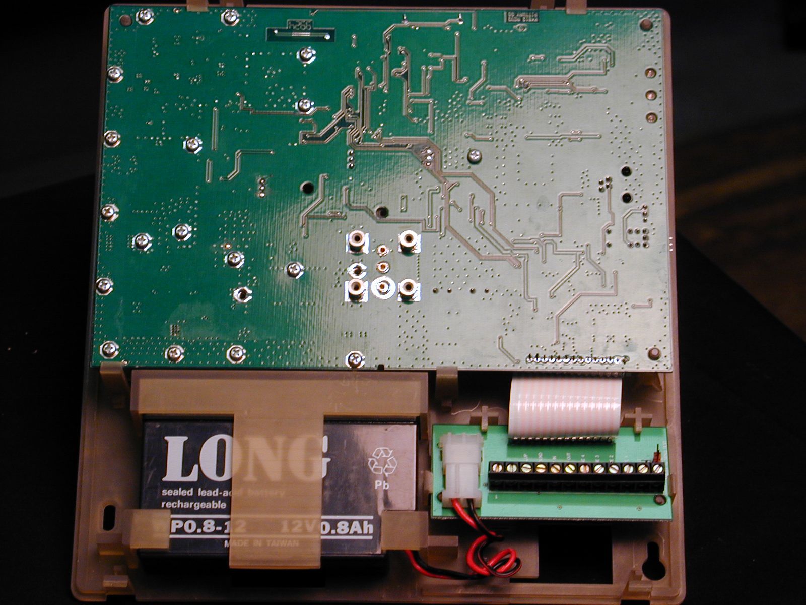
Ademco Inc.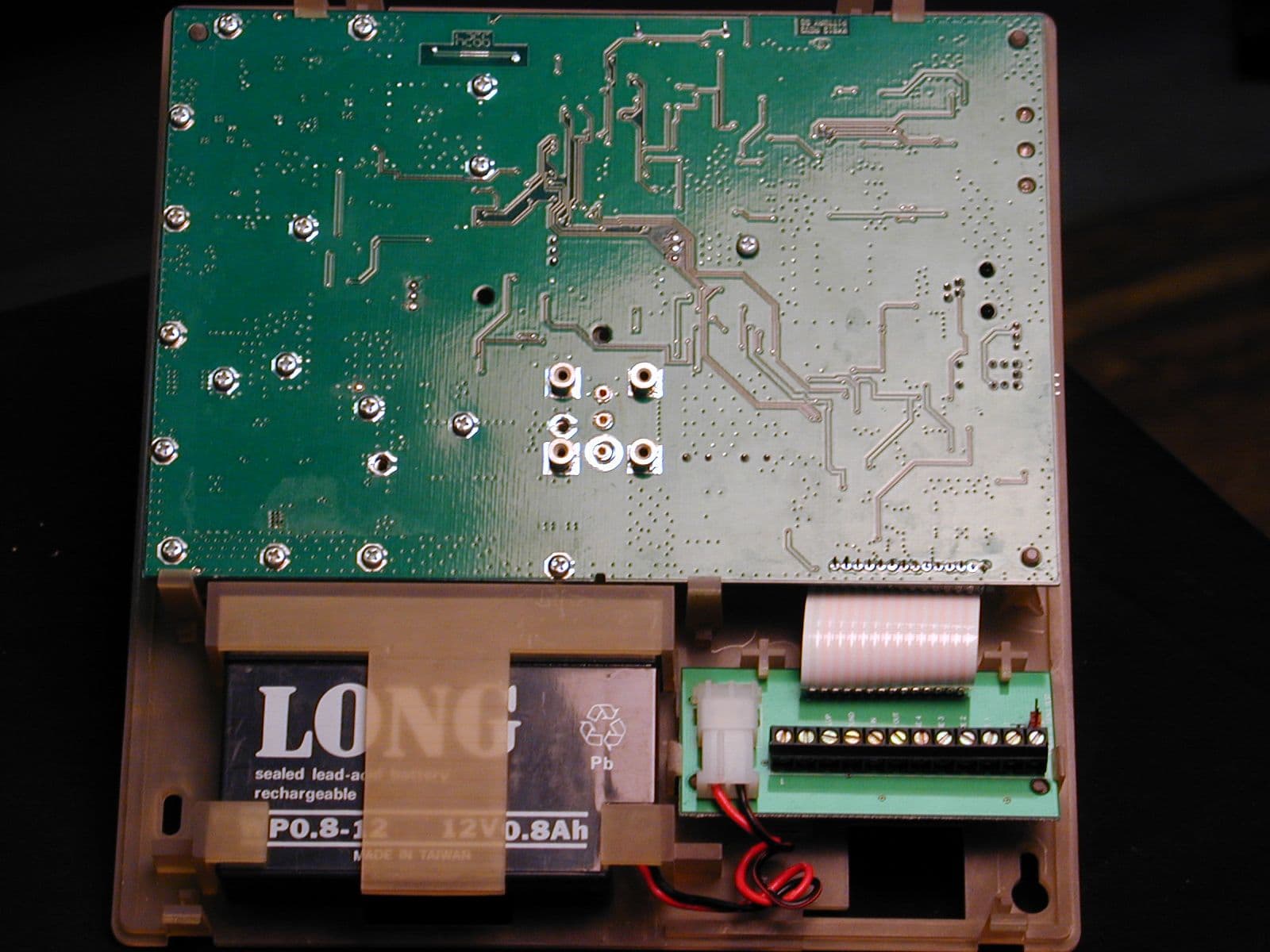
Click to zoom
Application Details
- Equipment Class
- TNB - Licensed Non-Broadcast Station Transmitter
- Date of Grant
- Mar 06, 2000
- Application Purpose
- Original Equipment
- Date of Application
- Jan 12, 2000
- Equipment Note
- LIcensed fixed location security transmitter
- Frequency Range
- 928.01250000 - 928.33750000
- Company
- Ademco Inc.
- Country
- United States
Documents & Files
Document Text
Text extracted from the exhibit documents filed with the FCC. Open a document above to read the original.
Users Manual
N7734V1 10/96 7720PLUS SYNTHESIZED SUBSCRIBER RADIO INSTALLATION INSTRUCTIONS DRAFT TABLE OF CONTENTS SYSTEM FEATURES & OPERATION2OPEN/CLOSE TELCO & TAMPER ZONE SEL. 15 Features2Redundant Central Station Reporting15 General Operation3Exiting Program Mode/Setting Defaults17 LED Indications4ECP Mode Unique Programming18 Radio Fault Led Patterns4ANTENNA MOUNTING20 Low Battery Detection5Selecting A Site 20 SETTING THE JUMPER OPTIONS6Standard Wire Antenna21 JUMPER POSITIONS DIAGRAM7Optional Antennas21 WIRING, MOUNTING & POWERING8POST INSTALLATION CHECKLIST23 WIRING CONNECTIONS DIAGRAM9TESTING THE 7720PLUS24 PROGRAMMING THE 7720PLUS10Radio Transmission Test24 Using A 7720P Programming Tool10System Test24 Choosing Mode, ECP or Zone10ECP Status Codes26 Zone Mode Unique Programming11Last Detected Fault “E” Command27 Password Protection11Unique Contact ID Messages in ECP Mode27 Subscriber Information12TROUBLESHOOTING28 PULSE/DELAY ZONE DETECTION12NOTES FOR UL INSTALLATIONS29 INVERTED ZONE SELECTION13SPECIFICATIONS29 RESTORAL REPORTING14CONNECTIONS DIAGRAM30 N7734V1 10/96 Note to the Installer: Please read these Installation Instructions all the way through and become completely familiar with them before attempting to install a 7720PLUS subscriber radio. Note to pubs: change p/n and rev date – 3 – SYSTEM FEATURES & OPERATION Introduction The 7720PLUS self-contained synthesized subscriber radio is the subscriber end of a Long Range Radio alarm reporting system. As a communications link, by analogy to a telephone-based system, the 7720PLUS is comparable to a digital communicator connected by telephone line to a central monitoring station. Synthesized Frequency Selection The 7720PLUS can be programmed to operate on any authorized radio frequency. It is not necessary to stock a separate radio for each frequency the installer supports. Wireless Reporting All alarm and status messages are transmitted to the master station network via radio signals, which means faster and more secure reporting. Integrated Electronics The entire radio link equipment, except for the AC power supply unit, including interface, transmitter, battery and antenna, is housed in a single package, requiring only alarm inputs from a compatible alarm panel. Selection of Input Interfaces The 7720PLUS can monitor alarm inputs from the Ademco ECP interface, discrete 4 zone contact closures or their electrical equivalent NOTE: ECP features are compatible only with 685 software revision 4.7 and higher, and 685-5 software revision 8.1 and higher. Compatibility The 7720PLUS is compatible with existing installations using ADEMCO equipment or other control panels. The 7720PLUS can be used in conjunction with digital communicators on the same system, both acting as backup to one another (use an ADEMCO 659-EN Line Monitor connected to a zone input to report a line cut to backup a digital dialer), while connecting the radio fault output to a zone on the dialer. Built-in LED Indicators Three LEDs are used to indicate message transmissions, and radio faults. A blinking yellow LED indicates normal operation. (See LED Table Page 4). Built-in Tamper Protection For added protection, built-in cover tamper switches will trigger an alarm whenever the chassis cover is removed, thus protecting against unauthorized access to the 7720PLUS. The tamper zone number must be entered during programming to enable tamper reporting. A radio configured for ECP will automatically report the tamper status to the control panel, as well as to the Central Station Antenna Included The 7720PLUS can use either the supplied omni-directional wire antenna, or can use a 7825 outdoor antenna, 7625 omni-directional antenna, 7625-3DB antenna (if additional gain is required), a 7674, a 7674-13 YAGI antenna (if a directional antenna is required), by using the optional 7720ANT connector kit. For wall mounting, an optional 7825DP can be used. The supplied antenna mounts directly to the7720PLUS. The antennas (other than the wire and the dipole) can be mounted remotely, if desired, using the following pre-assembled coaxial cable, available from ADEMCO: 5ft – 4 – coax (P/N 7626-5), 12ft coax (P/N 7626-12), 25ft coax (P/N 7626-25HC), and 50ft coax (P/N 7626- 50HC). Programmable Features The 7720PLUS utilizes EEPROM (Electrically Erasable ROM) technology, which allows the 7720PLUS to be programmed with a 7720P Programming Tool. The programming options include radio frequency channel number (1 to 14), Telco channel assignments for fault input, inverted trigger inputs, delayed reporting channels (1-127 seconds delay, if selected), open/close/restore reporting channels, etc. Self -Diagnosing Transmitter Malfunctions of the transmitter, including antenna fault, radio transmitter fault, loss of external power, and low internal DC voltage can be displayed on the 7720P programming tool or reported on the ECP interface, as well as being transmitted to the master station, if the fault does not prevent such transmission. Faults can also trigger contact closures on a Form “C” relay to indicate radio faults. Power Supply The 7720PLUS is powered byan AC wall transformer, part number (TBD), whichprovides 12 volts AC to the radio on pins 1 and 2 of the terminal block. An internal rechargeable battery provides power to the radio in the event of AC power outage. This battery is charged from the AC power supply during normal operation of the radio. Low Battery Monitoring The 7720PLUS will notify the central station of a low battery condition whenever the battery voltage drops below 9.93V (+/- 2%). Low battery restore messages are reported “” when the battery voltage reaches 10.03V (+/-2.5%). A radio configured for ECP will report the battery status to the control panel as well as to the central station. Low Battery Shutdown In the absence of AC power, if battery voltage drops below 9.45 volts, the 7720PLUS will automatically shutdown and ALL LEDs WILL BE OFF. However, so long as there is AC power, in the norma…
Text truncated - open the document above for the full version.
Operational Description
§2.1033(c)(10)Schematic Diagram:See Schematic Diagram Exhibit files, 7721-1.pdf and 7721-2.pdf. Note: Component designations preceded by an ‘X’ are not present. Description of Circuits: Determining and Stabilizing the Frequency of the Transmitter The frequency is determined by a Temperature Compensated Voltage Controlled Crystal Oscillator (TCVCXO), A2, Ademco part number K3945, which operates at 12 MHz and is compensated to a stability of ±2.5PPM over the temperature range of -30EC to +75EC. A frequency synthesizer uses this 12 MHz as a source, and produces the RF output frequency on 14 channels in the range of 928.0125 MHz to 928.3375 MHz. The synthesizer is U10, Ademco part number N40-LMX1501. The programming of this chip originates with the on- board microprocessor, U4, and the channel information is stored in electrically programmable ROM U5. An output from U10-7 is filtered and processed thru comparator U33 to produce a logical “1" only when the loop is locked. The LOOPLOCK signal is fed to the microprocessor at U4-38, and inhibits the transmitter from being activated when it is not in a logical “1" state. Suppression of Spurious Radiation Each radio frequency stage of the transmitter after U15, a wide-band buffer, uses tuned circuits, comprised of a combination of distributed and lumped elements, which are designed to maximize power gain in the desired band of frequencies at 928 MHz, and minimize gain at frequencies where harmonic or subharmonic signals might exist. The entire radio frequency section of the transmitter is enclosed in a shield, with double-walled metalizing, which is mechanically connected to circuit ground by screws. The output of the final RF amplifier is also low-pass filtered by the structure shown on the schematic as “LOW PASS FILTER,” which is made up of lumped capacitors at C139 and C140, as well as distributed microstrip line elements. Phase-locked loop components, including time constants and VCO parameters, and modulation filtering, have been chosen so as to keep the spectrum and the occupied bandwidth within the prescribed limits. Connections which originate within the shield structure are typically either filtered by ferrite or resistive elements combined with bypass capacitors, or at least with bypass capacitors, and the 12 MHz clock, which is also used by the microprocessor, U4, has its high-frequency edges rounded off by series elements R381 and Z51, a ferrite bead, traversing the unshielded portion of the circuit board. To as great a degree as feasible, circuits have been kept compact, so as to minimize the area from which digital signals could be radiated, and most integrated circuits are bypassed to circuit ground near their power supply input. Virtually the entire far side of the circuit board, which contains no components, is ground plane. Limiting Modulation Modulation amplitude is invariant, since it consists of a data stream of digital “1's” and “0's”. The modulation is adjusted at the factory via potentiometers R1 and R43. Before being applied to the TCVCXO, it is low-pass filtered by components R4 and C18, and in the path to the 928 MHz VCO, by components R45, C48, and R62, C80. Since the modulation level is constant, no means of “limiting” it are provided or necessary. Limiting Power The power output is determined by the capability of the output transistor, Q4 (Ademco part number N15-BLT94), and the DC bias applied to it. The collector voltage is regulated, and the bias is adjusted at the factory. It is actually not possible to get any significant power greater than 5 watts at the antenna port using this particular part, at this bias. Radios are specified to ship with power level between +6 and +7 dBW.
Parts List/Tune Up Info
%********************************************************************* % * % Program : PC-FORM VERSION 8.6 * % Date : Jan 13 2000 * % Time : 10:22:56 AM * % File In : 7721.xnl * % File Out : 7721.mat * % Format : P-CAD MATERIALS LIST * % * %********************************************************************* ITEM SQTY PQTY COMP-NAME REFERENCE-DESIGNATOR DESCRIPTION ---- ---- ---- --------- ------------- ----------- 1 16 16 n87-103h R55 R162 R190 R176 DEPT=SMR PART#=N87-103 R408 R38 R263 R170 R88 VAL=10K WATT=1/16W R89 R86 R42 R105 R84 R372 R341 2 236 236 tp TP11 TP6 TP3 TP2 TP203 TP1 TP204 TP214 TP207 TP215 TP128 TP218 TP219 TP217 TP216 TP234 TP235 TP233 TP236 TP221 TP116 TP115 TP223 TP225 TP226 TP220 TP237 TP228 TP212 TP232 TP94 TP240 TP201 TP231 TP95 TP59 TP60 TP61 TP62 TP63 TP8 TP211 TP206 TP205 TP213 TP202 TP36 TP32 TP35 TP38 TP39 TP37 TP41 TP276 TP277 TP280 TP200 TP165 TP166 TP169 TP168 TP167 TP89 TP275 TP42 TP210 TP278 TP279 TP209 TP282 TP57 TP58 TP64 TP65 TP69 TP67 TP68 TP70 TP71 TP74 TP72 TP73 TP76 TP75 TP77 TP80 TP83 TP81 TP82 TP87 TP84 TP86 TP88 TP90 TP91 TP92 TP93 TP227 TP230 TP229 TP239 TP242 TP241 TP244 TP245 TP246 TP176 TP175 TP173 TP174 TP172 TP171 TP170 TP249 TP250 TP251 TP252 TP162 TP163 TP150 TP145 TP133 TP253 TP132 TP164 TP127 TP254 TP109 TP149 TP147 TP146 TP144 TP143 TP142 TP140 TP138 TP137 TP135 TP134 TP141 TP105 TP131 TP129 TP104 TP130 TP118 TP125 TP117 TP113 TP112 TP110 TP114 TP108 TP107 TP256 TP257 TP106 TP4 TP258 TP261 TP197 TP198 TP196 TP199 TP194 TP193 TP192 TP191 TP190 TP189 TP102 TP181 TP180 TP179 TP178 TP139 TP136 TP33 TP21 TP97 TP124 TP156 TP159 TP158 TP157 TP161 TP155 TP154 TP263 TP152 TP13 TP151 TP160 TP16 TP15 TP123 TP148 TP122 TP121 TP120 TP119 TP247 TP248 TP111 TP100 TP259 TP103 TP101 TP54 TP52 TP51 TP49 TP48 TP47 TP46 TP45 TP44 TP43 TP17 TP40 TP30 TP29 TP28 TP27 TP26 TP25 TP24 TP19 TP18 TP126 TP20 TP14 TP7 TP0 TP5 TP99 3 2 2 n78-333 C18 C4 DEPT=SMR PART#=N78-333 VAL=0.033MF VOLT=25V 4 2 2 ll020011 C26 C7 DEPT=SMR PART#=LL0200111 VAL=.33MF VOLT=16V 5 17 17 n77-470 C192 C381 C160 C159 DEPT=SMR PART#=N77-470 C158 C157 C155 C152 VAL=47pF VOLT=50V C151 C150 C212 C75 C71 C67 C171 C53 C191 6 3 3 n87-303h R65 R72 R202 DEPT=SMR PART#=N87-303 VAL=30K WATT=1/16W 7 2 2 n881001h R27 R28 DEPT=SMR PART#=N88-1001 VAL=1000 WATT=1/16W 8 6 6 n87-104h R168 R77 R149 R195 DEPT=SMR PART#=N87-104 R197 R164 VAL=100K WATT=1/16W 9 1 1 n78-472 C48 DEPT=SMR PART#=N78-472 VAL=4700pF VOLT=50V 10 13 13 n77-470h C174 C180 C3 C13 C65 DEPT=SMR PART#=N77-470 C133 C22 C21 C168 C14 VAL=47pF VOLT=50V C162 C190 C205 11 6 6 n78-102h C175 C81 C6 C23 C147 DEPT=SMR PART#=N78-102 C170 VAL=1000pF VOLT=50V 12 3 3 n5492 J9 J8 J7 DEPT=HI PART#=N5492 13 10 10 n3011b22 Z31 Z4 Z1 Z21 Z24 Z23 DEPT=SM Z22 Z7 Z20 Z8 PART#=N30-11B221SD 14 3 3 n72-105h C33 C19 C30 DEPT=SM PART#=N72-105 VAL=1MF VOLT=16V 15 16 16 n87-103 R51 R5 R3 R362 R294 DEPT=SMR PART#=N87-103 R346 R96 R100 R237 VAL=10K WATT=1/16W R104 R107 R47 R91 R92 R198 R328 16 4 1 n40-2901 U33 U33 U33 U33 DEPT=SM PART#=N40-2901 VAL=LM2901D 17 1 1 n15blt81 Q8 DEPT=SM PART#=N15-BLT81 VAL=BLT81 18 1 1 n78-683h C51 DEPT=SMR PART#=N78-683 VAL=68NF 19 1 1 n85-203 R43 DEPT=SMR PART#=N85-203 VAL=20K 20 11 11 n30-a02 Z28 Z27 Z29 Z30 Z2 Z25 DEPT=SM PART#=N30-A02 Z11 Z10 Z14 Z13 Z12 VAL=100MHZ 21 5 5 n77-390h C380 C78 C34 C55 C31 DEPT=SMR PART#=N77-390 VAL=39pF VOLT=50V 22 2 2 n87-240h R378 R14 DEPT=SMR PART#=N87-240 VAL=24 WATT=1/16W 23 1 1 n15blt94 Q4 DEPT=SMR PART#=N15-BLT94 TYPE=BLT94 24 4 1 n41hc125 U9 U9 U9 U9 DEPT=SM PART#=N41-HC125 VAL=MC54/74HC125A 25 7 7 n72-475 C211 C47 C54 C45 C46 DEPT=SM PART#=N72-475 C16 C112 VAL=4.7MF VOLT=16V 26 1 1 n30-10nc L35 DEPT=SM PART#=N30-10NC VAL=10NH 27 1 1 n8820 XA3 DEPT=HI PART#=N8820 VAL=MQE-001-938 28 2 2 n87-223 R41 R15 DEPT=SMR PART#=N87-223 VAL=22K WATT=1/16W 29 2 2 n77-330 C165 C166 DEPT=SMR PART#=N77-330 VAL=33pF VOLT=50V 30 1 1 k3945 A2 DEPT=SMR PART#=K3945 TYPE=RTVE- 204EFX5P-TS-12.00 VAL=12MHz 31 2 2 n87-102 R321 R402 DEPT=SMR PART#=N87-102 VAL=1K WATT=1/16W 32 4 4 n11-907a Q10 Q11 Q37 Q24 DEPT=SM PART#=N11-907A TYPE=PNP VAL=MMBT2907A 33 1 1 n87-240 R249 DEPT=SMR PART#=N87-240 VAL=24 WATT=1/16W 34 3 3 n20-2810 CR13 CR14 CR39 DEPT=SM PART#=N20-2810 VAL=1AMP VOLT=20V 35 6 6 n78-222 C80 C61 C99 C95 C96 DEPT=SMR PART#=N78-222 C97 VAL=2200pF VOLT=50V 36 9 9 n78-103h C15 C28 C153 C36 C86 DEPT=SMR PART#=N78-103 C77 C58 C56 C37 VAL=0.01uF VOLT=50V 37 1 1 n76-5r6h C142 DEPT=SMR PART#=N76-5R6 VAL=5.6pF VOLT=50V 38 1 1 n87-752 R16 DEPT=SMR PART#=N87-752 VAL=7.5K WATT=1/16W 39 1 1 n78-104 C17 DEPT=SMR PART#=N78-104 VAL=0.1MF VOLT=25V 40 1 1 n30-123 L10 DEPT=SM PART#=N30-123 VAL=.012MH 41 3 3 n402903p U13 U17 U18 42 6 3 n40-2903 U13 U13 U17 U18 U17 DEPT=SM U18 PART#=N40-LM2903 VAL=LM2903D 43 1 1 n78-332 C8 DEPT=SMR PART#=N78-332 VAL=3300PF VOLT=50V 44 1 1 n152791t U15 DEPT=SM PART#=N15-2791TB VAL=UPC2791TB 45 1 1 n88-1003 R103 DEPT=SMR PART#=N88-1003 VAL=100K WATT=1/16W 46 2 2 n77-101h C2 C210 DEPT=SMR PART#=N77-101 VAL=100pF VOLT=50V 47 2 2 n76-3r9 C63 C74 DEPT=SMR PART#=N76-3R9 VAL=3.9pF VOLT=50V 48 1 1 n87-470h R8 DEPT=SMR PART#=N87-470 VAL=47 WATT=1/16W 49 1 1 n30-6r8u L1 DEPT=SMR PART#=N30-6R8U VAL=6.8UH 50 1 1 n87-302 R189 DEPT=SMR PART#=N87-302 VAL=3K WATT=1/16W 51 7 7 n87-474h R57 R90 R93 R234 R95 DEPT=SMR PART#=N87-474 R99 R82 VAL=470K WATT=1/16W 52 2 2 n87-333h R24 R345 DEPT=SMR PART#=N87-333 VAL=33K WATT=1/16W 53 2 1 n42-6462 U16 U16 DEPT=SMR PART#=N42- LMC6462AIM 54 1 1 n87-683h R73 DEPT=SMR PART#=N87-683 VAL=68K WATT=1/16W 55 1 1 n76-3r9h C66 DEPT=SMR PART#=N76-3R9 VAL=3.9pF VOLT=50V 56 2 2 n77-221 C43 C144 DEPT=SMR PART#=N77-221 VAL=220pF VOLT=50V 57 6 6 n70-104h C156 C154 C69 C1 C105 DEPT=SM PART#=N70-104 C106 VAL=.1MF VOLT=50V 58 1 1 n74-6r2 C145 DEPT=SMR PART#=N74-6R2 VAL=6.2pF VOLT=50V 59 1 1 n87-302h R54 DEPT=SMR PART#=N87-302 VAL=3K WATT=1/16W 60 2 2 n87-221 R379 R13 DEPT=SMR PART#=N87-221 VAL=220 WATT=1/16W 61 2 2 n76-1r5h C9 C12 DEPT=SMR PART#=N76-1R5 VAL=1.5pF VOLT=50V 62 1 1 n30-r10t L16 DEPT=SM …
Text truncated - open the document above for the full version.
Parts List/Tune Up Info
EXHIBIT 2 §2.1033(c)(9) 7720PLUS TUNE-UP PROCEDURE Power is applied to the 7720PLUS from 120VAC through the supplied 10:1 transformer. A 7720P Programming Tool is used to program the operating frequency, typically channel #10, and other operational functions listed in the Installation and Operating instructions. Once the 7720PLUS is programmed, the input voltage is removed. The unit is then put into its “Diagnostic Mode” by grounding pin #16 of the microprocessor, U4, while input voltage is re-applied. ADJUSTMENTS 1. Battery Charging Voltage : R357 is adjusted such that, with no battery present, a voltage of +13.8V is present at the output of Q55 (VBAT). 2. Operating Frequency : A voltage $ +5V is applied to Zone #3. This causes the 7720PLUS to transmit a low level CW signal. The TCVCXO, A2, is adjusted (if necessary) to the programmed operating frequency ±460Hz. 3. Modulation : Initially R1 and R43 are set to the middle of their adjustment range. A voltage $+5V is applied to Zone 1. This causes the 7720PLUS to transmit a low level frequency modulated signal with modulation frequency of 625Hz. R1 is adjusted for a frequency deviation of 3kHz ±200Hz. The voltage is then removed from Zone #1. A voltage $ +5V is applied to Zone #2. This causes the 7720plus to transmit a low level frequency modulated signal with a modulation frequency of 2500Hz. R43 is adjusted for a frequency deviation of 3kHz ±200Hz. Adjustment of R1 and R43 are repeated as needed. Verification of the adjustment is done by applying a voltage $+5V to Zones #1 and #2. This causes the 7720PLUS to transmit a low level frequency modulated signal comprised of pseudo-random data. The deviation measured shall be 3kHz ±200Hz. 4. Output Power : A voltage $ +5V is applied to Zones #1 and #3. This causes bias voltage to be applied to the PA, Q4. No RF power is transmitted. R39 is adjusted for a 1V level at U16 pin #1. This corresponds to quiescent PA collector current of 50mA. A voltage $ +5V is applied to Zones #2 and #3. This causes the 7720PLUS to transmit at full power for 50ms every 1.35 seconds (a typical transmission cycle). The output power is measured and if it is >+37dBm R39 is adjusted to obtain +37dBm.
Test Report
RF Power Output (§2.1046) MEASUREMENT PROCEDURE: A resistive RF attenuator of 50 ohm impedance as the output of the transmitter was connected to the transmitter RF output terminal. The RF output of the test sample was coupled to a peak power meter through the RF attenuator. The output power was then measured by the RF peak power meter. Using a variable transformer and voltmeter, the input voltage was varied. Measurements were made with the transmitter being supplied with 85%, 100% and 115% of its rated input voltage. The measurement was done for channels representing the upper, lower and middle of the band of operation. The test setup was as shown below: Test Results: The results of the above test are shown on the next page. RF ATTENUATOR RF PEAK POWER METER TEST SAMPLE 7720PLUS VARIABLE AC TRANSFORMER 120VAC INPUT DIGITAL VOLTMETER AC TRANSFORMER AC INPUT ALARM DEVICE MANUFACTURING COMPANY 160 Eileen Way Syosset, NY 11791 TABULAR DATA SHEET TEST METHOD: TEST SAMPLE: MODEL No:SERIAL No: TEST SPECS: OPERATING MODE: TESTED BY:DATE: DATA SHEETOF RF POWER OUTPUT (§2.1046) INTEGRATED RADIO TRANSMITTER 7720PLUS FCC RULES & REGULATIONS, §101.113(a) and §101.147(b) (GRANDFATHER CLAUSE) TRANSMITTING T. MOTT NA OCTOBER 27,1999 SUPPLY VOLTAGE CHANNEL POWER OUTPUT LIMIT VAC No.MHzdBWdBW 102 102 102 120 120 120 138 138 138 7 1 7 14 1 7 14 1 7 14 928.0125 928.0125 928.0125 928.1625 928.1625 928.1625 928.3375 928.3375 928.3375 6.88 6.88 6.88 6.88 6.88 6.88 6.88 6.88 6.88 1 1 7 FREQUENCY RF POWER OUTPUT OF THE TEST SAMPLE DOES NOT EXCEED THE SPECIFIED LIMIT.
Test Report
Modulation Characteristics (§2.1047) Measurement Procedure: The test sample was aligned to give +/- 3kHz deviation as per the alignment procedure. The sample was then coupled to the Modulation Domain Analyzer through a 20dB attenuator. With the unit transmitting in normal operation, the display of the Modulation Domain Analyzer was photographed. This was done for the frequencies representing the lower, middle and upper channels. The test setup was as shown below: Test Results: Pictures of the demodulated signals are shown on the following pages. MODULATION DOMAIN ANALYZER RF OUTPUT TEST SAMPLE 7720PLUS RF ATTENUATOR ALARM DEVICE MANUFACTURING COMPANY 160 Eileen Way Syosset, NY 11791 TABULAR DATA SHEET TEST METHOD: TEST SAMPLE: MODEL No:SERIAL No: TEST SPECS: OPERATING MODE: TESTED BY:DATE: DATA SHEETOF MODULATION CHARACTERISTICS (§2.1047) INTEGRATED RADIO TRANSMITTER 7720PLUS NA FCC RULES AND REGULATIONS, §101.109(c) TRANSMITTING T.MOTT 13 NOVEMBER 2, 1999 ALARM DEVICE MANUFACTURING COMPANY 160 Eileen Way Syosset, NY 11791 TABULAR DATA SHEET TEST METHOD: TEST SAMPLE: MODEL No:SERIAL No: TEST SPECS: OPERATING MODE: TESTED BY:DATE: DATA SHEETOF MODULATION CHARACTERISTICS (§2.1047) INTEGRATED RADIO TRANSMITTER 7720PLUS NA FCC RULES AND REGULATIONS, §101.109(c) TRANSMITTING T.MOTT NOVEMBER 2,1999 2 3 ALARM DEVICE MANUFACTURING COMPANY 160 Eileen Way Syosset, NY 11791 TABULAR DATA SHEET TEST METHOD: TEST SAMPLE: MODEL No:SERIAL No: TEST SPECS: OPERATING MODE: TESTED BY:DATE: DATA SHEETOF MODULATION CHARACTERISTICS (§2.1047) INTEGRATED RADIO TRANSMITTER 7720PLUS NA FCC RULES AND REGULATIONS, §101.109(c) TRANSMITTING T.MOTT NOVEMBER 2,1999 33
Test Report
RF OUTPUT RF ATTENUATOR SPECTRUM ANALYZER Occupied Bandwidth (§2.1049) Measurement Procedure: The RF output of the test sample was coupled to a spectrum analyzer through a 20dB attenuator. The test sample was put into the Dignostic Mode by grounding pin #16 at power up. Zone 3 was pulled "high". This causes the 7720PLUS to transmit a pseudo-random modulated signal of 140ms duration every second. The spectrum analyzer was set such that the Reference Level is the Peak RF Envelope Power level. The analyzer was set to Peak Hold Detect until a full display was attained. A plot was then made of the analyzer display. The test setup was as shown below: Test results: The results for the above test are shown on the following sheets. TEST SAMPLE 7720PLUS ALARM DEVICE MANUFACTURING COMPANY 160 Eileen Way Syosset, NY 11791 TEST METHOD: TEST SAMPLE: MODEL No:SERIAL No: TEST SPECS: OPERATING MODE: TESTED BY:DATE: DATA SHEETOF OCCUPIED BANDWIDTH (§2.1049) INTEGRATED RADIO TRANSMITTER 7720PLUS NA FCC RULES & REGULATIONS, §101.109(c) TRANSMITTING T.MOTTOCTOBER 27, 1999 1 1 THE OCCUPIED BANDWIDTH OF THE TEST SAMPLE DOES NOT EXCEED THE SPECIFIED LIMIT.
Test Report
Spurious Emissions at the Antenna Terminal (§2.1051) Measurement Procedure: The RF output of the test sample was coupled to a spectrum analyzer through a 20dB attenuator. The test sample was then modulated as stated in the Occupied Bandwidth test. The frequency range was scanned from the lowest frequency generated by the test sample to the tenth harmonic of the fundamental. Plots were made of the spectrum analyzer displays. The limits for the spurious emission are calculated utilizing the measured Peak RF Envelope Power and the limits stated in §101.111(a)(6). Above 1500MHz, High Pass Filters were placed between the 20dB attenuator and the spectrum analyzer to ensure the measured responses were true and not due to the spectrum analyzer and the fundamental frequency. The spectrum analyzer was triggered by the 7720PLUS's V4 to ensure that the analyzer was sweeping during transmission. Due to analyzer Resolution Bandwidth /Sweep Time limitations and the 7720PLUS's RF transmission cycle timing, Page #2 is composed of two averaged plots of 100 transmissions each. All others plots are Peak Hold detected. The test setup was as shown below. Test Results: The results for the above test are shown on the following sheets. TEST SAMPLE 7720PLUS RF ATTENUATOR SPECTRUM ANALYZER HIGH PASS FILTER (ABOVE 1500MHz) ALARM DEVICE MANUFACTURING COMPANY 160 Eileen Way Syosset, NY 11791 TEST METHOD: TEST SAMPLE: MODEL No:SERIAL No: TEST SPECS: OPERATING MODE: TESTED BY:DATE: DATA SHEETOF INTEGRATED RADIO TRANSMITTER 7720PLUS FCC RULES & REGULATIONS, §101.111(a)(6) SPURIOUS EMISSIONS AT THE ANTENNA TERMINAL (§2.1051) TRANSMITTING T. MOTTOCTOBER 28, 1999 1 12 NA ALARM DEVICE MANUFACTURING COMPANY 160 Eileen Way Syosset, NY 11791 TEST METHOD: TEST SAMPLE: MODEL No:SERIAL No: TEST SPECS: OPERATING MODE: TESTED BY:DATE: DATA SHEETOF T. MOTT SPURIOUS EMISSIONS AT THE ANTENNA TERMINAL (§2.1051) INTEGRATED RADIO TRANSMITTER 7720PLUS NA FCCRULES AND REGULATIONS, §101.111(a)(6) OCTOBER 28, 1999 POWER ON, TRANSMITTING 2 12 SPURIOUS EMISSIONS AT THE TEST SAMPLES ANTENNA TERMINAL DO NOT EXCEED THE SPECIFIED LIMITS. ALARM DEVICE MANUFACTURING COMPANY 160 Eileen Way Syosset, NY 11791 TEST METHOD: TEST SAMPLE: MODEL No:SERIAL No: TEST SPECS: OPERATING MODE: TESTED BY:DATE: DATA SHEETOF SPURIOUS EMISSIONS AT THE ANTENNA TERMINAL (§2.1051) INTEGRATED RADIO TRANSMITTER 7720PLUS FCC RULES & REGULATIONS, §101.111(a)(6) TRANSMITTING T.MOTT OCTOBER 28,1999 NA 3 12 SPURIOUS EMISSIONS AT THE TEST SAMPLE ANTENNA TERMINAL DO NOT EXCEED THE SPECIFIED LIMIT. ALARM DEVICE MANUFACTURING COMPANY 160 Eileen Way Syosset, NY 11791 TEST METHOD: TEST SAMPLE: MODEL No:SERIAL No: TEST SPECS: OPERATING MODE: TESTED BY:DATE: DATA SHEETOF SPURIOUS EMISSIONS AT THE ANTENNA TERMINAL ( §2.1051) INTEGRATED RADIO TRANSMITTER 7720PLUS FCC PART 101.111 (6) TRANSMITTING T.MOTT OCTOBER 28, 1999 NA 412 SPURIOUS EMISSIONS AT THE TEST SAMPLES ANTENNA TERMINAL DO NOT EXCEED THE SPECIFIED LIMIT. ALARM DEVICE MANUFACTURING COMPANY 160 Eileen Way Syosset, NY 11791 TEST METHOD: TEST SAMPLE: MODEL No:SERIAL No: TEST SPECS: OPERATING MODE: TESTED BY:DATE: DATA SHEETOF 5 12 SPURIOUS EMISSIONS AT THE ANTENNA TERMINAL (§2.1051) INTEGRATED RADIO TRANSMITTER 7720PLUS NA FCC RULES & REGULATIONS, §101.111(a)(6) TRANSMITTING T. MOTT OCTOBER 28, 1999 SPURIOUS EMISSIONS AT THE TEST SAMPLES ANTENNA TERMINAL DO NOT EXCEED THE SPECIFIED LIMIT. ALARM DEVICE MANUFACTURING COMPANY 160 Eileen Way Syosset, NY 11791 TEST METHOD: TEST SAMPLE: MODEL No:SERIAL No: TEST SPECS: OPERATING MODE: TESTED BY:DATE: DATA SHEETOF SPURIOUS EMISSIONS AT THE ANTENNA TERMINAL (§2.1051) INTEGRATED RADIO TRANSMITTER 7720PLUSNA FCC RULES & REGULATIONS, §101.111(a)(6) TRANSMITTING T. MOTTNOVEMBER 1, 1999 6 12 SPURIOUS EMISSIONS AT THE TEST SAMPLES ANTENNA TERMINAL DO NOT EXCEED THE SPECIFIED LIMIT. ALARM DEVICE MANUFACTURING COMPANY 160 Eileen Way Syosset, NY 11791 TEST METHOD: TEST SAMPLE: MODEL No:SERIAL No: TEST SPECS: OPERATING MODE: TESTED BY:DATE: DATA SHEETOF SPURIOUS EMISSIONS AT THE ANTENNA TERMINAL INTEGRATED RADIO TRANSMITTER NA 7720PLUS FCC RULES & REGULATIONS, §101.111(a)(6) TRANSMITTING T. MOTT 7 12 NOVEMBER 1, 1999 SPURIOUS EMISSIONS AT THE TEST SAMPLES ANTENNA TERMINAL DO NOT EXCEED THE SPECIFIED LIMIT. ALARM DEVICE MANUFACTURING COMPANY 160 Eileen Way Syosset, NY 11791 TEST METHOD: TEST SAMPLE: MODEL No:SERIAL No: TEST SPECS: OPERATING MODE: TESTED BY:DATE: DATA SHEETOF SPURIOUS EMISSIONS AT THE ANTENNA TERMINAL (§2.1051) INTEGRATED RADIO TRANSMITTER NA FCC RULES & REGULATIONS, §101.111(a)(6) TRANSMITTING T. MOTT NOVEMBER 1, 1999 8 12 7720PLUS SPURIOUS EMISSIONS AT THE TEST SAMPLES ANTENNA TERMINAL DO NOT EXCEED THE SPECIFIED LIMIT. ALARM DEVICE MANUFACTURING COMPANY 160 Eileen Way Syosset, NY 11791 TEST METHOD: TEST SAMPLE: MODEL No:SERIAL No: TEST SPECS: OPERATING MODE: TESTED BY:DATE: DATA SHEETOF SPURIOUS EMISSIONS AT THE ANTENNA TERMINAL (§2.1051) INTEGRATED RADIO TRANSMITTER 7720PLUS NA FCC RULES & REGULATIONS, §101.111(a)(6) TRANSMITTING T. MOTT NOVEMBER 1, 1999 9 12 SPURIOUS EMISSIONS AT THE TEST SAMPLES ANTENNA TERMINAL DO NOT EXCEED THE SPECIFIED LIMIT. ALARM DEVICE MANUFACTURING COMPANY 160 Eileen Way Syosset, NY 11791 TEST METHOD: TEST SAMPLE: MODEL No:SERIAL No: TEST SPECS: OPERATING MODE: TESTED BY:DATE: DATA SHEETOF SPURIOUS EMISSIONS AT THE ANTENNA TERMINAL (§2.1051) INTEGRATED RADIO TRANSMITTER 7720PLUS NA FCC RULES & REGULATIONS, §101.111(a)(6) TRANSMITTING T. MOTT NOVEMBER 1, 1999 1012 SPURIOUS EMISSIONS AT THE TEST SAMPLES ANTENNA TERMINAL DO NOT EXCEED THE SPECIFIED LIMIT. ALARM DEVICE MANUFACTURING COMPANY 160 Eileen Way Syosset, NY 11791 TEST METHOD: TEST SAMPLE: MODEL No:SERIAL No: TEST SPECS: OPERATING MODE: TESTED BY:DATE: DATA SHEETOF SPURIOUS EMISSIONS AT THE ANTENNA TERMINAL (§2.1051) INTEGRATED RADIO TRANSMITTER 7720PLUS NA FCC RULES & REGULATIONS, §101.111(a)(6) TRANSMITTING T. MOTT NOVEMBER 1, 1999 1112 SPURIOUS EMISSIONS AT THE TEST SAMPLES ANTENNA TERMINAL DO N…
Text truncated - open the document above for the full version.
Test Report
§2.1033(c)(14)Test and Measurement Data: All tests and measurements shown, §2.1046 thru §2.1055, in this report were made in accordance with the applicable FCC Rules & Regulations noted. All testing was performed at ADEMCO (Alarm Device Manufacturing Company) whose complete facility data package is on file with the FCC at the Laurel, Maryland Laboratory. Prior to testing, the test sample is certified by the applicant to be tuned up in accordance with the manufacturer’s specifications.
Test Report
RF Power Output (§2.1046) MEASUREMENT PROCEDURE: A resistive RF attenuator of 50 ohm impedance as the output of the transmitter was connected to the transmitter RF output terminal. The RF output of the test sample was coupled to a peak power meter through the RF attenuator. The output power was then measured by the RF peak power meter. Using a variable transformer and voltmeter, the input voltage was varied. Measurements were made with the transmitter being supplied with 85%, 100% and 115% of its rated input voltage. The measurement was done for channels representing the upper, lower and middle of the band of operation. The test setup was as shown below: Test Results: The results of the above test are shown on the next page. RF ATTENUATOR RF PEAK POWER METER TEST SAMPLE 7720PLUS VARIABLE AC TRANSFORMER 120VAC INPUT DIGITAL VOLTMETER AC TRANSFORMER AC INPUT ALARM DEVICE MANUFACTURING COMPANY 160 Eileen Way Syosset, NY 11791 TABULAR DATA SHEET TEST METHOD: TEST SAMPLE: MODEL No:SERIAL No: TEST SPECS: OPERATING MODE: TESTED BY:DATE: DATA SHEETOF RF POWER OUTPUT (§2.1046) INTEGRATED RADIO TRANSMITTER 7720PLUS FCC RULES & REGULATIONS, §101.113(a) and §101.147(b) (GRANDFATHER CLAUSE) TRANSMITTI…
Text truncated - open the document above for the full version.
Contact Information
Applicant
Christian Fouth(Sr. Wireless Certification Engineer)
Technical Contact
Ademco Mfg.Doug McGarrett
[email protected]1-516-921-6704
160 Eileen Way · Syosset, New York · United States
Technical Specifications
| # | Rule Parts | Frequency Range | Power Output | Emission | Tolerance |
|---|---|---|---|---|---|
| 1 | 101 | 928.0125 MHz - 928.3375 MHz | 5 W | 13K4F1D | 5.0000000000 ppm |
Other Applications from Ademco Inc.

CFS8DL5800MINIV
Jan 28, 2026Wireless Alarm Transmitter
Equipment Class
DXX - Part 15 Low Power Communication Device Transmitter
CFS8DLWTS800
Jan 12, 2026Wireless Alarm Transmitter
Equipment Class
DTS - Digital Transmission SystemCFS8DLCAMWEWI1
Jul 25, 2024VX5 HD Indoor Camera
Equipment Class
DTS - Digital Transmission System
CFS8DLCAMWEWO1
Sep 17, 2023VX3 HD Outdoor Camera
Equipment Class
NII - Unlicensed National Information Infrastructure TX
CFS8DLLMD500A
Jul 20, 2023Wireless door/window contact
Equipment Class
DTS - Digital Transmission System