CFS8DL5800COXTLFWireless Carbon Monoxide Transmitter
Ademco Inc.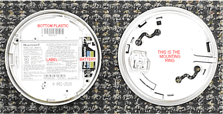
Click to zoom
Application Details
- Equipment Class
- DSR - Part 15 Remote Control/Security Device Transceiver
- Date of Grant
- Mar 08, 2010
- Application Purpose
- Original Equipment
- Date of Application
- Mar 07, 2010
- Equipment Note
- Wireless Carbon Monoxide Transmitter
- Frequency Range
- 344.94000000 - 344.94000000
- Company
- Ademco Inc.
- Country
- United States
Documents & Files
Document Text
Text extracted from the exhibit documents filed with the FCC. Open a document above to read the original.
Users Manual
5800CO Carbon Monoxide Detector with Built-in Wireless Transmitter INSTALLATION AND SETUP GUIDE GENERAL INFORMATION The 5800CO is a 3V battery powered wireless Carbon Monoxide (CO) detector intended for use with wireless alarm systems that support 5800 series devices. Refer to control/communicator installation instructions for compatibility. The detector consists of an electrochemical carbon monoxide sensor assembly coupled to a wireless transmitter. The transmitter can send alarm, trouble, tamper, and battery condition messages to the system’s receiver. Refer to the wireless system’s instructions for the maximum number of transmitters that can be supported. NOTICE: This manual should be left with the owner/user of this equipment. IMPORTANT: This detector must be tested and maintained regularly following NFPA 72 requirements. WARNING: This product is intended for use in ordinary indoor locations of dwelling units, including homes, residential buildings, hotels, schools, dormitories, and day care centers. It is not intended for use in industrial factories or commercial parking garages. Detector Description • Listed to UL standard 2075 (pending) • Supervised • Local sounder • Dual LED’s • Test/Hush button • Surface mount to wall or ceiling • Optional drywall anchors included The 5800CO contains a piezoelectric horn which generates the ANSI S3.41 temporal 4 pattern in an alarm condition (see note below Table 1 for temporal 4 pattern). In alarm, a message is also sent to the wireless control panel and the detector’s zone number is displayed at the console. The alarm message is transmitted every 4 seconds until the carbon monoxide condition has cleared and the detector has reset. During an alarm condition, pressing the detector’s test button will silence the piezoelectric horn for 5 minutes. Once the detector has reset, a RESTORE message is transmitted to the control panel and the transmitter’s zone number can be cleared from the panel. The mounting base installation is simplified by the incorporation of features compatible with drywall fasteners or other methods that provide a method for securing the detector in place. During initial power-up, the red and green LEDs will blink together once every 10 seconds up to four times. It takess about 30 seconds for the detector’s CO sensor to stabilize (see Table 1). After power-up has completed and the detector is functioning normally within its listed sensitivity range, the green LED blinks once every 10 seconds. The LED indication must not be used in place of the tests specified under TESTING THE DETECTOR. In a trouble condition, the red LED will blink once every 10 seconds (refer to Table 1). If the detector senses a low battery condition, the red LED blinks once every 45 seconds. Two LEDs and a sounder on the detector provide local visual and audible indication of the detector’s status as listed in Table 1. Table 1: Detector LED Modes Green LED Red LED Sounder Normal (standby) Blinks every 10 seconds Off Off Alarm/Test Off Blinks every 1 second Temporal 4 Pattern † Low Battery Off Blinks every 45 seconds Chirp every 45 sec after LED blinks for 7 days Communication Fail Off Blinks every 5 seconds Off Trouble Off Blinks every 5 seconds One chirp every 45 seconds Detector End-of- Life Off Blinks every 10 seconds Off Power Up Blinks every 10 secs †† (w/red LED) Blinks every 10 secs †† (w/green LED) Off † Temp 4 pattern is repeated pattern of four short beeps followed by a five second pause. When the detector has been in alarm for 30 minutes, the alarm signal will be given once every minute. If ambient conditions return to normal, the detector will self-restore out of alarm and into Normal (standby) mode. †† Red and green LEDs blink a total of four times, once every 10 seconds. Hush feature: If required, the audible alarm can be silenced for 5 minutes by pushing the button marked “Test/Hush”. The red alarm light will continue to flash in temp-4 pattern. If carbon monoxide is still present after the 5 minute hush period, the audible alarm will sound. The hush feature will not operate at levels above 350 ppm (parts per million) carbon monoxide. Trouble feature: When the sensor supervision is in a trouble condition, the detector will send a trouble signal to the panel. Trouble conditions include an open circuit, sensor removal (tamper), and sensor end of life. End of Life Timer feature: When the detector has reached the end of its life, the trouble contact will open. This indicates that the CO sensor inside the detector has passed the end of its life and must be replaced. This detector’s lifespan is approximately six years from the date of manufacture. Refer to Detector Replacement section Low Battery Detection: The 5800CO is powered by a single 3- volt CR123A or DL123A Lithium battery (included). The detector checks for a low battery at least every 65 minutes. If a low battery is detected, the transmitter sends a low battery message to the control panel, which beeps and displays the detector’s zone number. In addition, the red LED of the detector will blink every 45 seconds and the test button will be disabled. This condition will exist for a minimum of 7 days, and then the detector’s horn will “chirp” about every 45 seconds. Pressing the test button during this time will silence the chirps for 12 hours. The battery should be replaced BEFORE the chirps begin. Be sure to replace the battery with a fresh one. – 2 – BATTERY INSTALLATION AND REPLACEMENT To replace the battery: 1. Remove the detector from its mounting base by twisting the detector counterclockwise. Remove the battery, and dispose properly. 2. To ensure proper power-down sequence, wait a minimum of 20 seconds before installing new battery. 3. Install a new 3-volt CR123A Lithium battery in the battery compartment. Follow the polarity diagram inside the compartment. 4. Reinstall the detector onto the mounting base by turning the detector clockwise. 5. Test the detector as described in the TESTI…
Text truncated - open the document above for the full version.
External Photos
EXHIBIT 4-1 EXTERNAL PICTURES CFS8DL5800COXTLF / 573F-5800COXTLF TOP PLASTIC: BOTTOM PLASTIC:
ID Label/Location Info
EXHIBIT 8 LABEL INFORMATION CFS8DL5800COXTLF / 573F-5800COXTLF SECTION 2.1033 (c) and Part 15.21 SECTION 2.1033 (c) Label and label location - A photo showing the identification label clearly (you must be able to see the name and FCC ID number), and the location on the device. In lieu of a photo for this, you may submit a engineer’s drawing. Part 15.21 Statement - for all intentional and unintentional radiators is also printed on the label. All devices shall bear the following statement in a conspicuous location on the device: “ This device complies with Part 15 of the FCC Rules Operation is subject to the following two conditions: (1) this device may not cause harmful interference, and (2) this device must accept any interference received, including interference that may cause undesired operation. “ ENGINEERS DRAWING: EXACT PHYSICAL LOCATION ON THE UNIT:
Internal Photos
EXHIBIT 4-2 INTERNAL PICTURES CFS8DL5800COXTLF / 573F-5800COXTLF PCB IN PLASTIC: TOP OF PCB: BOTTOM OF PCB:
Test Setup Photos
EXHIBIT 5-2 CFS8DL5800COXTLF / 573F-5800COXTLF PICTURES OF THE TEST SETUP SECTION 2.1093 (c) SECTION 2.1093 (c) Photo of the test setup shall be provided. THE UUT: OBLIQUE SENSE VERTICAL OBLIQUE SENSE HORIZONTAL .HORIZONTAL SENSE VERTICAL HORIZONTAL SENSE HORIZONTAL VERTICAL SENSE VERTICAL . VERTICAL SENSE HORIZONTAL THE SITE: THE TEST EQUIPMENT THE TEST TECHNICIAN COMPLETE VIEW OF THE SITE
Contact Information
Applicant
Christian Fouth(Sr. Wireless Certification Engineer)
Technical Contact
Honeywell International Inc.Kenneth Eskildsen
[email protected]516-577-5878
2 Corporate Center Drive · Melville, New York · United States
Test Firm
Honeywell International Inc.Mark Schmidt
Technical Specifications
| # | Rule Parts | Frequency Range | Power Output |
|---|---|---|---|
| 1 | 15.231 | 344.94 MHz - 344.94 MHz | - |
Other Applications from Ademco Inc.

CFS8DL5800MINIV
Jan 28, 2026Wireless Alarm Transmitter
Equipment Class
DXX - Part 15 Low Power Communication Device Transmitter
CFS8DLWTS800
Jan 12, 2026Wireless Alarm Transmitter
Equipment Class
DTS - Digital Transmission SystemCFS8DLCAMWEWI1
Jul 25, 2024VX5 HD Indoor Camera
Equipment Class
DTS - Digital Transmission System
CFS8DLCAMWEWO1
Sep 17, 2023VX3 HD Outdoor Camera
Equipment Class
NII - Unlicensed National Information Infrastructure TX
CFS8DLLMD500A
Jul 20, 2023Wireless door/window contact
Equipment Class
DTS - Digital Transmission System