CFS8DL5800PIRRES1Wireless Motion Sensor
Ademco Inc.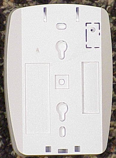
Click to zoom
Application Details
- Equipment Class
- DSC - Part 15 Security/Remote Control Transmitter
- Date of Grant
- Mar 11, 2012
- Application Purpose
- Original Equipment
- Date of Application
- Mar 11, 2012
- Equipment Note
- Wireless Motion Sensor
- Frequency Range
- 344.94000000 - 344.94000000
- Company
- Ademco Inc.
- Country
- United States
Documents & Files
Document Text
Text extracted from the exhibit documents filed with the FCC. Open a document above to read the original.
Users Manual
5800PIR-RES Wireless Motion Sensor - Installation Instructions PRELIMINARY DRAFT 8/24/09 - 1 - CONNECT THE BATTERY, ENROLL THE SENSOR, CONDUCT GO / NO GO TEST, AND PERFORM WALK TEST / METTRE LES PILES EN PLACE , ENROLL THE SENSOR, CONDUCT GO / NO GO TEST, AND PERFORM WALK TEST ACCESSORIES / ACCESSOIRES TOP OPEN / OUVERTURE LOCATION / EMPLACEMENT 1 2 7.5 - 8 ft MOUNT / INSTALLATION 4 3 2 Recommended Screws: #6 (3.5 mm) DETECTION PATTERNS / COUVERTURE DE DETECTION A B (2.3 - 2.4 m) 35' / 11m Wide Angle Animal Immune Lens (P/N 5-532-719-00) Top View / Vue de Dessus Side View / Vue de Cote 1 2 0 7' 2m 20' 6m 27' 8m 35' 11m 0 7' 2m 20' 6m 13' 4m 13' 4m 7' 2m 20' 6m 13' 4m 1 2 3 4 5 10 9 8 7 6 11 12 13 14 15 16 17 18 19 20 0 7' 2m 20' 6m 27' 8m 35' 11m 13' 4m 7'6" (2.3m) 0 1 Panasonic CR123A / Duracell DL123A / Honeywell 466 Observe correct polarity / Observe correct polarity See page 2 for more information / See page 2 for more information Satisfactory / Satisfaisant / Satisfactorio No / Non / No - Use only left OR right side corner mounting holes. SMB-10 1 (P/N 0-000-110-01) Swivel Mount Bracket SMB-10C (P/N 0-000-111-01) Swivel Mount Ceiling Bracket SMB-10T 1 (P/N 0-000-155-01) Swivel Mount Bracket w/Tamper IS2500-HSLK 1 35’ x 40’ (11 m x 12 m) High Security Lens Kit IS2500-PALK 2 35’ x 40’ (11 m x 12 m) Pet Alley Lens Kit 1 Not verified by ETL. Mounting Height: Hauteur de montage: Altura de la instalación: 1 7 – 9 ft (2.1 m – 2.7 m). 2 4 ft (1.2 m). 5800PIR-RES Wireless Motion Sensor - Installation Instructions PRELIMINARY DRAFT 8/24/09 - 2 - ENROLL THE SENSOR Enroll the sensor in the control panel prior to its usage in the system. Refer to the control panel instructions for programming details. Program the sensor as an “RF” type (supervised RF) device. To enroll: connect the battery and wait for power up to end (see LED Indications table). When prompted for the serial number, activate the sensor (wave a hand in front of the lens) to enroll the sensor. Loop 1 Pulse count 2; Up to 80 lbs. Animal Immunity LED INDICATIONS Power UpBlinks once per second (for < 45 seconds) Indicator LED Walk TestON for 3 seconds = Loop 1 / Low Sensitivity Alarm Flickers rapidly for 3 seconds = walk test period ended Condition MOUNT THE SENSOR (See page 1) Before mounting the transmitter permanently, conduct Go/No Go tests (see control panel manual) to verify adequate signal strength and reorient or relocate the sensor if necessary. For Animal (Pet) Immunity: • Install the sensor where animals cannot come within 6 ft (1.8 m) of the sensor by climbing on furniture or other objects. • Aim the sensor away from stairways, furniture or other objects that can be climbed on by animals. • Do not use optional swivel mount brackets. WALK TESTING The 10 minute walk test mode begins after power up, and can be restarted by removing and replacing the battery. As you walk through the detection pattern, the sensor LED will light for 3 seconds to indicate each alarm detection. Note: In walk test mode all transmissions will be sent as they occur. During normal operation, only one transmission sequence will occur within a 3-minute period to conserve battery life. TROUBLESHOOTING Problem: The system displays a “low battery” message. Solution: Replace the battery within 7 days. SPECIFICATIONS Power: Battery* (included). 1 x 3 V, Lithium; CR123A / DL 123A / 466 Battery Life, years (typical): 5 RF Frequency: 345 MHz Operating Temperature: (for indoor use environment) 14° to 131° F (-10° to 55° C) Relative Humidity, no condensation: 95% max. Detectable Walk Rate: 0.7 – 7ft/Sec. (0.2 – 2.0m/Sec.) Temperature Compensation: Advanced Dual Slope APPROVALS / LISTINGS • FCC part 15, Class B verified • IC, ICES-003, Class B verified • C-Tick • CE • SIA-PIR-01 Passive Infrared detector standard features for false alarm immunity. • cETLus Listed COMPLIANCE NOTES • Product must be tested at least once each year. • Product must be installed within the protected area only. FCC NOTICE: This equipment has been tested and found to comply with the limits for a Class B digital device, pursuant to Part 15 of the FCC Rules. These limits are designed to provide reasonable protection against harmful interference in a residential installation. This equipment generates, uses and can radiate radio frequency energy and, if not installed and used in accordance with the instructions, may cause harmful interference to radio communications. However, there is no guarantee that interference will not occur in a particular installation. If this equipment does cause harmful interference to radio or television reception, which can be determined by turning the equipment off and on, the user is encouraged to try to correct the interference by one or more of the following measures: − Reorient or relocate the receiving antenna. − Increase the separation between the equipment and receiver. − Connect the equipment into an outlet on a circuit different from that to which the receiver is connected. − Consult the dealer or an experienced radio/television technician for help. The user is cautioned that changes or modifications not expressly approved by Honeywell could void the user’s authority to operate this equipment. IC NOTICE : This Class B digital device complies with the Canadian ICES-003. Cet appareil numérique de la Classe B est conforme à la norme NMB-003 du Canada. This device complies with Part 15 of the FCC Rules and RSS-210 of the IC rules. Operation is subject to the following two conditions: (1) this device may not cause harmful interference, and (2) this device must accept any interference received, including interference that may cause undesired operation. Cet appareil est conforme à la partie 15 des règles de la FCC & la norme CNR-210 des règles d’IC. L’utilisation de ce dispositif est autorisée seulement aux deux conditions suivantes ; (1) il ne doit pas produire de brouillage, et (2) l’utilisateur du dispositif doit être prêt à accepter tout brouillage radioéle…
Text truncated - open the document above for the full version.
External Photos
EXHIBIT 4-1 CFS8DL5800PIRRES1 / 573F-5800PIRRES1 EXTERNAL PHOTOS TOP PLASTIC: BOTTOM PLASTIC:
ID Label/Location Info
EXHIBIT 8 CFS8DL5800PIRRES1 / 573F-5800PIRRES1 LABEL INFORMATION BECAUSE OF LIMITED LABEL SIZE THE PART 15 STATEMENT IS IN THE USERS MANUAL ("II") ENGINEERS DRAWING OF THE LABEL: ACTUAL PHYSICAL LOCATION OF THE LABEL:
Internal Photos
EXHIBIT 4-2 CFS8DL5800PIRRES1 / 573F-5800PIRRES1 INTERNAL PHOTOS PCB IN PLASTIC: TOP OF PCB: BOTTOM OF PCB:
Test Report
EXHIBIT 5-1 CFS8DL5800PIRRES1 / 573F-5800PIRRES1 Report of Measurements . Measurements for the Intentional Radiator,and OBW were made in accordance with the procedures and reporting requirements at: Honeywell's OATS ( FCC No: 152762 & IC No:573F-1 ) which is located at: 2 Corporate Center Drive, Melville, NY 11747. Measurements were made in accordance with the procedure and reporting requirements of ANSI C63.4-2003. The Test Set-Up (C63.4 section 10.1.3) is shown in EXHIBIT 5-2; "Test Setup Photos". The sequence of testing (C63.4 section 10.1.7) for radiated emissions is as follows: A preliminary scan was conducted with the receiver antenna close to the EUT in order to identify the emission characteristics of the EUT (C63.4 section 8.3.1.1). The antenna and EUT were then placed at the proper separation ( 3 Meters) with the EUT positioned at 80 cm on a non-conducting turntable. The EUT was rotated on the turntable to maximize the received signal strength, then the receiver antenna height was varied between one (1) and four (4) Meters to further maximize the received reading. Thereafter, the device was again rotated to a peak output position and the antenna height wa s re-adjusted for maximum received signal. This procedure was re-iterated until there was no fu rther increase in signal level. This procedure was performed with the EUT rotating in three orthogonal planes (C63.4 section 13.1.4.1) to generate a final maximum reading which is recorded on the radiated emissions result sheet. Similar measurements were made on the receiver to ensure compliance as an unintentional radiator. Note, The Spectrum Analyzer resolution bandwidths set as follows; (Video Bandwidth is always set 3X greater than RBW) For occupied bandwidth measurements, RBW = 30KHz and VBW = 100KHz. For radiated emissions below 1 GHz, the RBW = 100kHz. Detector function set to peak. For radiated emissions above 1 GHz, the RBW = 1MHz. Detector function set to peak. TRANSMITTER RADIATED EMISSIONS are recorded in "EXHIBIT 5-3". OCCUPIED BANDWIDTH is recorded in "EXHIBIT 5-4". TEST EQUIPMENT ( per C63.4 section 10.1.4) is recorded in "EXHIBIT 6".
Test Report
HONEYWELL SECURITY & CUSTOM ELECTRONICSREV 2011D 2 Corporate Center Drive Melville, NY 11747 EXHIBIT 5-3FCC ID: CFS8DL PIR-RES1 Date :4-Aug 2011Tested by:Approved by K. Eskildsen 5800PIRRES1 Notes: (1)Fo:344.94 (2) Detector = Peak (3) Frequency range scanned to 4 GHz. Emissions not reported were more than 20dB below the specified unit. [(Meter reading + Cable/Amp factor + Antenna factor) / 20 )] (4) Conv. Reading = 10 (5) Corr. Reading = Conv. Reading X Duty Cycle (6) Six Highest Emissions Recorded Freq. (MHz): Sense Antenna Polarity (V/H): THE ORENTATION OF THE UUT Meter Reading (dB uV): Cable/Amp Factor (dB): Antenna Factor (dB/m): Conv. Reading (uV/M): Duty Cycle (%): Corr. Reading (uV/M): Limit @ 3M (uV/M): HV 344.94VV79.292.314.64 64,788.8 10.0% 6478.97292 689.88VV21.593.219.91171.810.0%17.2729 1034.82VH17.384.424.40203.710.0%20.4500 1379.76VV16.074.927.84275.710.0%27.6500 1724.70VO16.295.529.10350.310.0%35.0729 2069.64VV16.376.433.92683.110.0%68.3729 2414.58VV16.566.931.64568.910.0%56.9729 2759.52 VV 16.377.4 33.16702.310.0%70.2500 3104.46VV16.447.934.03828.910.0%82.9729 3449.40VV16.159.232.12747.310.0%74.7729 4000 LAST CAL 05 FEB 11 CABLE C LAST CAL 17-MAY-11 BICONILOG S/N:00029390 G. BARBATO Test Sample (model): Test specification: FCC Part 15, Sub-part C and RSS 210 , Issue 8 Test method: ANSI C63.4 - 2003
Test Report
EXHIBIT 5-4 CFS8DL5800PIRRES1 / 573F-5800PIRRES1 OCCUPIED BANDWIDTH MAXIMUM OCCUPIED BANDWIDTH = 862.35 KHz 5800PIRRES1 OCCUPIED BANDWIDTH: 212.4 KHz
Test Report
EXHIBIT 6 TEST EQUIPMENT USED CFS8DL5800PIRRES1 / 573F-5800PIRRES1 Part 15.231, ANSI C63.4 , RSS 210 This is a list of all test equipment used. Test Equipment list for Honeywell OATS & Conducted Line: Equipment Mfg Model Cal Date Cal Due Spectrum Analyzer Rohde & Schwarz FSEA20 10/19/10 10 /19/11 Antenna (‘Biconilog’) ETS (EMCO)Lindgren 3149 09/09/10 09/09/11 PLEASE SEE PAGE 2-7 FOR TEST EQUIPMENT TRACEABILITY If you need any additional i nformation from Honeywell please contact: Greg Barbato RF Engineer (Acting for Ken Eskildsen) Phone (Direct): (516) 577-5863 Email: [email protected]
Test Setup Photos
EXHIBIT 5-2 TEST SETUP PHOTOS CFS8DL5800PIR1 / 573F-5800PIR1 UUT VERT , SENSE HORZ: UUT HORZ , SENSE HORZ: UUT OBLQ , SENSE HORZ: UUT VERT , SENSE VERT: UUT HORZ , SENSE VERT: UUT OBLQ , SENSE VERT: PICTURE OF THE HONEYWELL OATS AT: 2 CORPORATE CENTER DRIVE MELVILLE, NY 11747
Contact Information
Applicant
Christian Fouth(Sr. Wireless Certification Engineer)
Technical Contact
Honeywell International Inc.Kenneth Eskildsen
[email protected]516 577 5878
2 Corporate Center Drive · Melville, New York · United States
Test Firm
Honeywell International Inc.Mark Schmidt
Technical Specifications
| # | Rule Parts | Frequency Range | Power Output |
|---|---|---|---|
| 1 | 15.231 | 344.94 MHz - 344.94 MHz | - |
Other Applications from Ademco Inc.

CFS8DL5800MINIV
Jan 28, 2026Wireless Alarm Transmitter
Equipment Class
DXX - Part 15 Low Power Communication Device Transmitter
CFS8DLWTS800
Jan 12, 2026Wireless Alarm Transmitter
Equipment Class
DTS - Digital Transmission SystemCFS8DLCAMWEWI1
Jul 25, 2024VX5 HD Indoor Camera
Equipment Class
DTS - Digital Transmission System
CFS8DLCAMWEWO1
Sep 17, 2023VX3 HD Outdoor Camera
Equipment Class
NII - Unlicensed National Information Infrastructure TX
CFS8DLLMD500A
Jul 20, 2023Wireless door/window contact
Equipment Class
DTS - Digital Transmission System