CFS8DL5800RRRelay Receiver
Ademco Inc.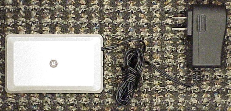
Click to zoom
Application Details
- Equipment Class
- CYY - Communications Receiver used w/Pt 15 Transmitter
- Date of Grant
- Mar 25, 2012
- Application Purpose
- Original Equipment
- Date of Application
- Mar 25, 2012
- Equipment Note
- Relay Receiver
- Frequency Range
- 344.94000000 - 344.94000000
- Company
- Ademco Inc.
- Country
- United States
Documents & Files
Document Text
Text extracted from the exhibit documents filed with the FCC. Open a document above to read the original.
Users Manual
5877 Relay Receiver / Relay Receiver / Relay Receiver / Relay Receiver Installation Instructions / Instructions de montage (FRC) / Installation Instructions(LAES) / Installation Instructions (LAPT) INTRODUCTION / INTRODUCTION / INTRODUCTION / INTRODUCTION The 5877 wireless relay module allows control of non-security system devices from compatible 5800 series wireless keys. The module also includes an LED that can provide panel system status information. The 5877 wireless relay module allows control of non-security system devices from compatible 5800 series wireless keys. The module also includes an LED that can provide panel system status information. The 5877 wireless relay module allows control of non-security system devices from compatible 5800 series wireless keys. The module also includes an LED that can provide panel system status information. The 5877 wireless relay module allows control of non-security system devices from compatible 5800 series wireless keys. The module also includes an LED that can provide panel system status information. OPEN OPEN – FR-C OPEN – LA-ES OPEN – LA-PT 5877-OPEN-V0 1 2 3 MOUNT MOUNT – FR-C MOUNT – LA-ES MOUNT – LA-PT • Use the double-sided tape (supplied) to mount the sensor. • Optional screws (supplied) are recommended. • Use the double-sided tape (supplied) to mount the sensor. • Optional screws (supplied) are recommended. • Use the double-sided tape (supplied) to mount the sensor. • Optional screws (supplied) are recommended. • Use the double-sided tape (supplied) to mount the sensor. • Optional screws (supplied) are recommended. NOTE: Mounting screws must be used in installations where temperatures drop to freezing 32° F (0° C). NOTE: Mounting screws must be used in installations where temperatures drop to freezing 32° F (0° C). NOTE: Mounting screws must be used in installations where temperatures drop to freezing 32° F (0° C). NOTE: Mounting screws must be used in installations where temperatures drop to freezing 32° F (0° C). PLUG IN 12VDC TRANSFORMER PLUG IN 12VDC TRANSFORMER – FR-C PLUG IN 12VDC TRANSFORMER – LA-ES PLUG IN 12VDC TRANSFORMER – LA-PT SPECIFICATIONS SPECIFICATIONS – FR-C SPECIFICATIONS - LA-ES SPECIFICATIONS –LS-PT Electrical: 12VDC Power Supply; Operating Current 29- 31mA / Electrical: 12VDC Power Supply; Operating Current 29- 31mA / Electrical: 12VDC Power Supply; Operating Current 29- 31mA / Electrical: 12VDC Power Supply; Operating Current 29- 31mA / Environmental Conditions: 14° to 122° F (-10° to 50° C); < 90% RH (non-condensing) Environmental Conditions: 14° to 122° F (-10° to 50° C); < 90% RH (non-condensing) Environmental Conditions: 14° to 122° F (-10° to 50° C); < 90% RH (non-condensing) Environmental Conditions: 14° to 122° F (-10° to 50° C); < 90% RH (non-condensing) Frequency: 345 MHz Frequency: 345 MHz Frequency: 345 MHz Frequency: 345 MHz Dimensions: 4.5” H x 2.75” W x 0.25” D; (114.3mm x 69.85mm x 6.351mm) Dimensions: 4.5” H x 2.75” W x 0.25” D; (114.3mm x 69.85mm x 6.351mm) Dimensions: 4.5” H x 2.75” W x 0.25” D; (114.3mm x 69.85mm x 6.351mm) Dimensions: 4.5” H x 2.75” W x 0.25” D; (114.3mm x 69.85mm x 6.351mm) Compatibility: Honeywell LYNX Series Controls, 5883H, 6160RF and 6150RF Keypads produced after March 2007 (P/NSA6150RFAS-T3 Printed Circuit Board). 5800 series Encrypted remotes not supported. Compatibility: Honeywell LYNX Series Controls, 5883H, 6160RF and 6150RF Keypads produced after March 2007 (P/NSA6150RFAS-T3 Printed Circuit Board). 5800 series Encrypted remotes not supported. Compatibility: Honeywell LYNX Series Controls, 5883H, 6160RF and 6150RF Keypads produced after March 2007 (P/NSA6150RFAS-T3 Printed Circuit Board). ). 5800 series Encrypted remotes not supported. Compatibility: Honeywell LYNX Series Controls, 5883H, 6160RF and 6150RF Keypads produced after March 2007 (P/NSA6150RFAS-T3 Printed Circuit Board). ). 5800 series Encrypted remotes not supported. APPROVALS / LISTINGS • FCC part 15, Class B verified • IC, ICES-003, Class B verified COMPLIANCE NOTES Product must be tested at least once each year. Product must be tested at least once each year. Product must be tested at least once each year. Product must be tested at least once each year. REFER TO THE INSTALLATION INSTRUCTIONS FOR THE RECEIVER/CONTROL WITH WHICH THIS DEVICE IS USED FOR DETAILS REGARDING LIMITATIONS OF THE ENTIRE ALARM SYSTEM. <FR-C> REFER TO THE INSTALLATION INSTRUCTIONS FOR THE RECEIVER/CONTROL WITH WHICH THIS DEVICE IS USED FOR DETAILS REGARDING LIMITATIONS OF THE ENTIRE ALARM SYSTEM. <LA-ES> REFER TO THE INSTALLATION INSTRUCTIONS FOR THE RECEIVER/CONTROL WITH WHICH THIS DEVICE IS USED FOR DETAILS REGARDING LIMITATIONS OF THE ENTIRE ALARM SYSTEM. <LA-PT> REFER TO THE INSTALLATION INSTRUCTIONS FOR THE RECEIVER/CONTROL WITH WHICH THIS DEVICE IS USED FOR DETAILS REGARDING LIMITATIONS OF THE ENTIRE ALARM SYSTEM. 5877-MOUNTING-V0 Mounting Screws Mounting Screws Mounting Screws Mounting Screws Double-sided Tape Double-sided Tape Double-sided Tape Double-sided Tape Mounting Surface Mounting Surface Mounting Surface Mounting Surface Relay Terminals Relay Terminals Relay Terminals Relay Terminals Mounting Holes (2) Mounting Holes (2) Mounting Holes (2) Mounting Holes (2) 12 Vdc Power Supply Connector 12 Vdc Power Supply Connector 12 Vdc Power Supply Connector 12 Vdc Power Supply Connector 12 Vdc Power Supply Receptacle 12 Vdc Power Supply Receptacle 12 Vdc Power Supply Receptacle 12 Vdc Power Supply Receptacle LED LED LED LED Program Button Program Button Program Button Program Button Jumper Jumper Jumper Jumper 5877-PARTS-LBLD-V0 NO NC COM 1 2 3 5877 Relay Receiver / Relay Receiver / Relay Receiver / Relay Receiver Installation Instructions / Instructions de montage (FRC) / Installation Instructions(LAES) / Installation Instructions (LAPT) CONFIGURE THE 5877 TO USE WITH 5800 SERIES WIRELESS KEYS, ENROLL WIRELESS KEYS INTO MODULE 1. Press (one second) and release the Program button; the LED will start flashing GREEN. 2. Press…
Text truncated - open the document above for the full version.
Users Manual
5877 Relay Receiver / Relay Receiver / Relay Receiver / Relay Receiver Installation Instructions / Instructions de montage (FRC) / Installation Instructions(LAES) / Installation Instructions (LAPT) INTRODUCTION / INTRODUCTION / INTRODUCTION / INTRODUCTION The 5877 wireless relay module allows control of non-security system devices from compatible 5800 series wireless keys. The module also includes an LED that can provide panel system status information. The 5877 wireless relay module allows control of non-security system devices from compatible 5800 series wireless keys. The module also includes an LED that can provide panel system status information. The 5877 wireless relay module allows control of non-security system devices from compatible 5800 series wireless keys. The module also includes an LED that can provide panel system status information. The 5877 wireless relay module allows control of non-security system devices from compatible 5800 series wireless keys. The module also includes an LED that can provide panel system status information. OPEN OPEN – FR-C OPEN – LA-ES OPEN – LA-PT 5877-OPEN-V0 1 2 3 MOUNT MOUNT – FR-C MOUNT – LA-ES MOUNT – LA-PT • Use the double-sided tape (supplied) to mount the sensor. • Optional screws (supplied) are recommended. • Use the double-sided tape (supplied) to mount the sensor. • Optional screws (supplied) are recommended. • Use the double-sided tape (supplied) to mount the sensor. • Optional screws (supplied) are recommended. • Use the double-sided tape (supplied) to mount the sensor. • Optional screws (supplied) are recommended. NOTE: Mounting screws must be used in installations where temperatures drop to freezing 32° F (0° C). NOTE: Mounting screws must be used in installations where temperatures drop to freezing 32° F (0° C). NOTE: Mounting screws must be used in installations where temperatures drop to freezing 32° F (0° C). NOTE: Mounting screws must be used in installations where temperatures drop to freezing 32° F (0° C). PLUG IN 12VDC TRANSFORMER PLUG IN 12VDC TRANSFORMER – FR-C PLUG IN 12VDC TRANSFORMER – LA-ES PLUG IN 12VDC TRANSFORMER – LA-PT SPECIFICATIONS SPECIFICATIONS – FR-C SPECIFICATIONS - LA-ES SPECIFICATIONS –LS-PT Electrical: 12VDC Power Supply; Operating Current 29- 31mA / Electrical: 12VDC Power Supply; Operating Current 29- 31mA / Electrical: 12VDC Power Supply; Operating Current 29- 31mA / Electrical: 12VDC Power Supply; Operating Current 29- 31mA / Environmental Conditions: 14° to 122° F (-10° to 50° C); < 90% RH (non-condensing) Environmental Conditions: 14° to 122° F (-10° to 50° C); < 90% RH (non-condensing) Environmental Conditions: 14° to 122° F (-10° to 50° C); < 90% RH (non-condensing) Environmental Conditions: 14° to 122° F (-10° to 50° C); < 90% RH (non-condensing) Frequency: 345 MHz Frequency: 345 MHz Frequency: 345 MHz Frequency: 345 MHz Dimensions: 4.5” H x 2.75” W x 0.25” D; (114.3mm x 69.85mm x 6.351mm) Dimensions: 4.5” H x 2.75” W x 0.25” D; (114.3mm x 69.85mm x 6.351mm) Dimensions: 4.5” H x 2.75” W x 0.25” D; (114.3mm x 69.85mm x 6.351mm) Dimensions: 4.5” H x 2.75” W x 0.25” D; (114.3mm x 69.85mm x 6.351mm) Compatibility: Honeywell LYNX Series Controls, 5883H, 6160RF and 6150RF Keypads produced after March 2007 (P/NSA6150RFAS-T3 Printed Circuit Board). 5800 series Encrypted remotes not supported. Compatibility: Honeywell LYNX Series Controls, 5883H, 6160RF and 6150RF Keypads produced after March 2007 (P/NSA6150RFAS-T3 Printed Circuit Board). 5800 series Encrypted remotes not supported. Compatibility: Honeywell LYNX Series Controls, 5883H, 6160RF and 6150RF Keypads produced after March 2007 (P/NSA6150RFAS-T3 Printed Circuit Board). ). 5800 series Encrypted remotes not supported. Compatibility: Honeywell LYNX Series Controls, 5883H, 6160RF and 6150RF Keypads produced after March 2007 (P/NSA6150RFAS-T3 Printed Circuit Board). ). 5800 series Encrypted remotes not supported. APPROVALS / LISTINGS • FCC part 15, Class B verified • IC, ICES-003, Class B verified COMPLIANCE NOTES Product must be tested at least once each year. Product must be tested at least once each year. Product must be tested at least once each year. Product must be tested at least once each year. REFER TO THE INSTALLATION INSTRUCTIONS FOR THE RECEIVER/CONTROL WITH WHICH THIS DEVICE IS USED FOR DETAILS REGARDING LIMITATIONS OF THE ENTIRE ALARM SYSTEM. <FR-C> REFER TO THE INSTALLATION INSTRUCTIONS FOR THE RECEIVER/CONTROL WITH WHICH THIS DEVICE IS USED FOR DETAILS REGARDING LIMITATIONS OF THE ENTIRE ALARM SYSTEM. <LA-ES> REFER TO THE INSTALLATION INSTRUCTIONS FOR THE RECEIVER/CONTROL WITH WHICH THIS DEVICE IS USED FOR DETAILS REGARDING LIMITATIONS OF THE ENTIRE ALARM SYSTEM. <LA-PT> REFER TO THE INSTALLATION INSTRUCTIONS FOR THE RECEIVER/CONTROL WITH WHICH THIS DEVICE IS USED FOR DETAILS REGARDING LIMITATIONS OF THE ENTIRE ALARM SYSTEM. 5877-MOUNTING-V0 Mounting Screws Mounting Screws Mounting Screws Mounting Screws Double-sided Tape Double-sided Tape Double-sided Tape Double-sided Tape Mounting Surface Mounting Surface Mounting Surface Mounting Surface Relay Terminals Relay Terminals Relay Terminals Relay Terminals Mounting Holes (2) Mounting Holes (2) Mounting Holes (2) Mounting Holes (2) 12 Vdc Power Supply Connector 12 Vdc Power Supply Connector 12 Vdc Power Supply Connector 12 Vdc Power Supply Connector 12 Vdc Power Supply Receptacle 12 Vdc Power Supply Receptacle 12 Vdc Power Supply Receptacle 12 Vdc Power Supply Receptacle LED LED LED LED Program Button Program Button Program Button Program Button Jumper Jumper Jumper Jumper 5877-PARTS-LBLD-V0 NO NC COM 1 2 3 5877 Relay Receiver / Relay Receiver / Relay Receiver / Relay Receiver Installation Instructions / Instructions de montage (FRC) / Installation Instructions(LAES) / Installation Instructions (LAPT) CONFIGURE THE 5877 TO USE WITH 5800 SERIES WIRELESS KEYS, ENROLL WIRELESS KEYS INTO MODULE 1. Press (one second) and release the Program button; the LED will start flashing GREEN. 2. Press…
Text truncated - open the document above for the full version.
External Photos
EXHIBIT 4-1 CFS8DL5800RR EXTERNAL PHOTOS TOP PLASTIC: BOTTOM PLASTIC:
ID Label/Location Info
EXHIBIT 8 CRS8DL5800RR LABEL INFORMATION ENGINEERS DRAWING OF THE LABEL: EXACT LOCATION OF THE LABEL ON THE BACK PLASTIC:
Internal Photos
EXHIBIT 4-2 CFS8DL5800RR / 573F-5800RR INTERNAL PHOTOS PCB IN PLASTIC: TOP OF PCB: BOTTOM OF PCB:
Test Report
EXHIBIT 5-1 CFS8DL5800RR Report of Measurements . Measurements for the Unintentional Radiator were made in accordance with the procedures and reporting requirements at: Honeywell's OATS ( FCC No: 152762 & IC No:573F-1 ) which is located at: 2 Corporate Center Drive, Melville, NY 11747. Measurements were made in accordance with the procedure and reporting requirements of ANSI C63.4-2003. The Test Set-Up (C63.4 section 10.1.3) is shown in EXHIBIT 5-2; "Test Setup Photos". The sequence of testing (C63.4 section 10.1.7) for radiated emissions is as follows: A preliminary scan was conducted with the receiver antenna close to the EUT in order to identify the emission characteristics of the EUT (C63.4 section 8.3.1.1). The antenna and EUT were then placed at the proper separation ( 3 Meters) with the EUT positioned at 80 cm on a non-conducting turntable. The EUT was rotated on the turntable to maximize the received signal strength, then the receiver antenna height was varied between one (1) and four (4) Meters to further maximize the received reading. Thereafter, the device was again rotated to a peak output position and the antenna height wa s re-adjusted for maximum received signal. This procedure was re-iterated until there was no further increase in signal level. This procedure was performed with the EUT rotating in three orthogonal planes (C63.4 section 13.1.4.1) to generate a final maximum reading which is recorded on the radiated emissions result sheet. Similar measurements were made on the receiver to ensure compliance as an unintentional radiator. Note, The Spectrum Analyzer resolution bandwidths set as follows; (Video Bandwidth is always set 3X greater than RBW) For radiated emissions below 1 GHz, the RBW = 100kHz. Detector function set to peak. For radiated emissions above 1 GHz, the RBW = 1MHz. Detector function set to peak. TEST EQUIPMENT ( per C63.4 section 10.1.4) is recorded in "EXHIBIT 6".
Test Report
EXHIBIT 5-1 CFS8DL5800RR Report of Measurements . Measurements for the Unintentional Radiator were made in accordance with the procedures and reporting requirements at: Honeywell's OATS ( FCC No: 152762 & IC No:573F-1 ) which is located at: 2 Corporate Center Drive, Melville, NY 11747. Measurements were made in accordance with the procedure and reporting requirements of ANSI C63.4-2003. The Test Set-Up (C63.4 section 10.1.3) is shown in EXHIBIT 5-2; "Test Setup Photos". The sequence of testing (C63.4 section 10.1.7) for radiated emissions is as follows: A preliminary scan was conducted with the receiver antenna close to the EUT in order to identify the emission characteristics of the EUT (C63.4 section 8.3.1.1). The antenna and EUT were then placed at the proper separation ( 3 Meters) with the EUT positioned at 80 cm on a non-conducting turntable. The EUT was rotated on the turntable to maximize the received signal strength, then the receiver antenna height was varied between one (1) and four (4) Meters to further maximize the received reading. Thereafter, the device was again rotated to a peak output position and the antenna height wa s re-adjusted for maximum received signal. This procedure was re-iterated until there was no further increase in signal level. This procedure was performed with the EUT rotating in three orthogonal planes (C63.4 section 13.1.4.1) to generate a final maximum reading which is recorded on the radiated emissions result sheet. Similar measurements were made on the receiver to ensure compliance as an unintentional radiator. Note, The Spectrum Analyzer resolution bandwidths set as follows; (Video Bandwidth is always set 3X greater than RBW) For radiated emissions below 1 GHz, the RBW = 100kHz. Detector function set to peak. For radiated emissions above 1 GHz, the RBW = 1MHz. Detector function set to peak. TEST EQUIPMENT ( per C63.4 section 10.1.4) is recorded in "EXHIBIT 6".
Test Report
EXHIBIT 5-5 CLASS B RADIATED EMISSIONS CFS8DL5800RR / 573F-5800RR Honeywell EMC Radiated Emissions Class B vertical and horizontal 10.00M100.00M1.00G Frequency MHz 0 5.0 10.0 15.0 20.0 25.0 30.0 35.0 40.0 45.0 50.0 55.0 60.0 65.0 70.0 Amplitude dBμV Control #: GARAGE DOOR03:06:59 PM, Tuesday, February 28, 2012 C:\Tile4\Greg_B\GARAGE DOOR.TIL Operator: GREG Control # - GARAGE DOOR Product type - Model # - GARAGE DOOR Sample # - 02-28-2012 Aux equipment - CISPR 22 Class B Horizontal Peak Vertical Peak Horizontal QP Vertical QP
Test Report
EXHIBIT 5-6 CFS8DL5800RR CLASS B CONDUCTED EMISSIONS Honeywell EN 55022, Class B Line 1 Peak Readings 100.0K1.0M10.0M100.0M Frequency MHz 10.0 20.0 30.0 40.0 50.0 60.0 70.0 80.0 90.0 Amplitude dBμV Project #: GARAGE DOOR03:21:33 PM, Tuesday, February 28, 2012 C:\Tile4\Greg_B\GARAGE DOOR COND.TIL Operator: Greg B GARAGE DOOR GARAGE DOOR CISPR Class B QP Limit CISPR Class B Avg Limit Peak Scan CISPRA_QP CISPRA_AV LINE 1 FREQUENCY MHZ: CISPR B QP LIMIT DBuV QP READING DBuV QP MARGIN DB CISPR B AVG LIMIT DBuV AVG READING DBuV AVG MARGIN DB 150.0 KHz 66 NAN NAN 56 NAN NAN 500.0 KHz 56 NAN NAN 46 NAN NAN 725.52 KHz 56 42.3 -13.7 46 29.218 -16.782 5.0 MHz 56 NAN NAN 46 NAN NAN 5.0001 MHz 60 NAN NAN 50 NAN NAN 30.0 MHz 60 NAN NAN 50 NAN NAN Honeywell EN 55022, Class B Neutral Peak Readings 100.0K1.0M10.0M100.0M Frequency 0 10.0 20.0 30.0 40.0 50.0 60.0 70.0 80.0 90.0 Amplitude Project #: GARAGE DOOR03:29:26 PM, Tuesday, February 28, 2012 C:\Tile4\Greg_B\GARAGE DOOR COND.TIL Operator: Greg B GARAGE DOOR GARAGE DOOR CISPRB_QP CISPRB_AV C_Neutral CISPRA_QP CISPRA_AV LINE 2 (NEUT) FREQUENCY MHZ: CISPR B QP LIMIT DBuV QP READING DBuV QP MARGIN DB CISPR B AVG LIMIT DBuV AVG READING DBuV AVG MARGIN DB 150.0 KHz 66 NAN NAN 56 NAN NAN 463.28 KHz 57.05 41.63 -15.419 47.049 24.118 -22.932 500.0 KHz 56 NAN NAN 46 NAN NAN 723.77 KHz 56 42.82 -13.18 46 24.697 -21.303 965.81 KHz 56 40.82 -15.18 46 22.803 -23.197 1.4363 MHz 56 36.81 -19.19 46 19.448 -26.552 1.6623 MHz 56 38.54 -17.46 46 20.547 -25.453 1.4363 MHz 56 36.81 -19.19 46 19.448 -26.552 965.81 KHz 56 40.82 -15.18 46 22.803 -23.197 723.77 KHz 56 42.82 -13.18 46 24.697 -21.303 463.28 KHz 57.05 41.63 -15.419 47.049 24.118 -22.932 5.0 MHz 56 NAN NAN 46 NAN NAN 5.0001 MHz 60 NAN NAN 50 NAN NAN 30.0 MHz 60 NAN NAN 50 NAN NAN
Test Report
EXHIBIT 6 TEST EQUIPMENT USED . Part 15.231 , ANSI C63.4 , RSS 210 This is a list of all test equipment used. Test Equipment list for Honeywell OATS & Conducted Line: Equipm ent Mfg Model Cal Date Cal Due Spectrum Analyzer Rohde & Schwarz FSEA20 10/19/11 10/19/12 Antenna (‘Bi conilog’) ETS (EMCO)Lindgren 3149 08/22/11 08/22/12 Surge Suppressor Agilent (HP) HP11947A 05/12/11 05/12/12 LISN Com-Power LI-115 10/20/11 10/20/12 PLEASE SEE PAGE 2-7 FOR TEST EQUIPMENT TRACEABILITY If you need any additional information from Honeywell please contact: Greg Barbato RF Engineer (Acting for Ken Eskildsen) Phone (Direct): (516) 577-5863 Email: [email protected] Cert l.D.: 86798 An ESCO Technologies Company 1301 Arrow Point Drive Cedar Park, Texas 78613 (512) 531-6498 Operating Range: 80 MHz - 6 GHz Instrument Type: Biconilog (Type 5) Date Code: Afternate lD: 11242 Customer: HONEYWELL (NY) 26 - 1000 MHz, +/-0.9 dB; 1000 - 2000 MHz, +L0.8 dB; 2000 - 6000 MHz, +l-1 .2 dB 26 - 1000 MHz, +/-0.9 dB; 1000 - 2000 MHz, +10.8 dB; 2000 - 6000 MHz, +f l .3 dB 26 - 1000 MHz, +/-'1 .0 dB; 1000 - 2000 MHz, +l-1 .4 dgi 2000 - 6000 MHz, +12.3 dB Manufacturer: Model Number: ETS-Lindgren 31 49. s 000023192 22-Aug-11 3 meter, Horizontal and Vertical N'Jl,,r. K S\ETS.LINDGREIU- ;.:::;lii,-:,..,; *ffil"+ IACCREDITEDI Calibr.tlon taboreio.y Codltlc.to 1207,01 Certificate of Cal i bration Conformance Page I of 5 The instrument identifed below has been individually calibrated in compliance with the following standard(s): SAE, ARP-958 - 2003, Electromagnetic lnterference Measurement Antennas; Standard Calibration Method, Society of Automotive Engineers, Aerospace Recommended Practice. Fixed height, three antenna rotation, 1 meter separation. 3 meter separation performed per Annex C. Vertical calibration performed per above listed methodology. Environment: Laboratory MTE is maintained in a temperature controlled environment with ambient conditions from 18 to 28 C, relative humidity less than 90%. The instrument under test has been calibrated on an open air test site (OATS) with environment temperature conditions ranging from 0 to 40 C which has no known influences on measurement quality. Serial Number/ lD: 00045682 Tracking Number: Date Completed: Test Type: CalibrationUncertainty: 01m k=2, (95ok Confidence Level) 03m Test Remarks: Calibrated down to 26 MHz per customer request. Calibration Traceability: All Measuring and Test Equipment (MffE) identified below are traceable to the Sl units through the National lnstitute for Standards and Technology (NIST). Calibraiion Laboratory and Quality System controls are compliant with ISO/lEC 17025-2005 and ANSI/NCSL 2540-1 -1994. Standards and Equipment Used: Make / Model / Name / S/N / Recall Date Condition of Instrument Upon Receipt: In Tolerance to Internal Qualitv Standards On Release: In Tolerance to Internal Qualitv Standards Anritsu MS4623A Network Analyzer 99220119-Mar-12 This document provides traceability of measurements to recognized national standards using contrblled processes at the ETS-L|ndgren Calibration Laboratory. UncertaintieslistedarederivedfromthemethodsdescribedbyNlSTTechNotel29T. Thiscertificateandreportmaynotbereproduced,exceptinfull,withoutthe written approval of ETS-Lindgren Calibration Laboratory in accordance with ISO/IEC 1 7025-2005 and ANSI/NCSL 2540-1 -1994. QAF 1 1 27 (03/1 1 ) Calibration and fssued on 22-Aug-1 fssue Date:5l11l2AU General Calibration, Inc. 2 Mars Court, Boonton, New Jersey 07005 Phone (973)299-2950 Fax (973) 2994595 Certificate g; MR-18671 Purchase Order: 524758'2 Work Order #: MR450 Customer #: 0014,64 GENERAL CALIBMTION, INC. 2 MARS COURT 096188 Manufacturer: HP Description: TRANSIENTLIMITER D-epe rtm.enl;_".," "." T-epp,/RH;...." "_ ca],.lnlerya|.'- . c^af.-Qatp; ,- .,05"l1ila9j1 HONEYWELL SECURTTY (001464) 2 CORPORATE CENTER DRIVE MELVILLE. NY 11747 Asset Tag No.: 10131 ModelNumber: 119474 SerialNumber: 3107402782 22Ct45% tnspsetsd.Pyr .* *" UBl Jgb-Ide,..... --_ " _".[ilEnAmgSI 9slihrpli-o:Ssgu.lf; .** PA$"$HP -QaL,Due P"etp-;--^ ". -**0 111?3"12 12 MONTHS BOONTON. NJ O7OO5 Found In Tolerance and Left In 04t06t2012 GENERALCALIBRATION 503 SPECTRUM ANALYZER 04t1212012 GENERAL CALIBMTION 688 LEVEL GENEMTOR 03t14t2012 The above instrument has been checked and calibrated against the above working standard(s) which are,traceable to the NIST. The test limits stated in the report correspond to the published specifications of the equipment, at the points tested. Also, the collective uncertainties of measurement standards do not exceed 25olo of the tolerance- oj tle gngFqtgristics being^caljlgle_d, wheg,possible. The metrology procedures utitized conform to and satisry the requirements set forth in ANSI/NCSL 2540-1-1994, 10 CFR part 21, ISO 9001-2008, ISO 10012-2003, and M|L-STD 456624. Approved By t&do*na",& tWM:*"."*.,^-** General Calibration, Inc. - Q. A. Manager // .lilii.i(sffi s&lnnrrrrlS$s.N:uittl GENERAL CALIBRANON, INC. 2MARS COURT BOONTONNJOTOO5 ,,.:,.r;'f ll.tt,i.llWi Job No.: 076905 Manufaclu1gr: COM-POWER GENERAL CALIBRATION GENERAL CALIBRATION General Calibration, Inc. 2 Mars Court, Boonton, New Jersey 07005 Phone (973) 299-2950 Fax (973) 299-0595 DIGITAL MULTIMETER DIGITAL MULTIMETER Certihcate #: MR-19821 Work Order#: MR504 Customer #z 001464 :s.i.;lllt|l': wl r; (001464) #iiiiiiiilililliii.l 2 CORPORATE CENTER DRTVE MELVILLE,NY I1747 t.rlltrltit,tttuluuti,llliiliiiiliiiiilliii l||lllll$ffi b:i6$ssi*lltl'rl$tift{ ilrr,,,,,,rrtrt,tttitii::iiiiiiiitilltiiiiiliil* Asset Tag No.: Model Number: LI-l15 r1262 cal.Interval: 12 MONTH$_ . calibration Re_sull: ._PASSED 418 700 ',liilililltiiliiiiiiliiiliiitilitillllllllllllill$i'r;'..,',,l1'r'llllltlllllllltrlrl'rl.lii$i.lriiidiliffi*d,Ds!. 0211012012 This is to certif' that General Calibration, Inc. is A2LA accredited and that its calibration system is in compliance with ISO/1EC17025-2005" ANSI NCSL 2540- 1, ANSI NCSL 2540'3,andISO900l:2008. Thetestlimitsstatedinthereportcor…
Text truncated - open the document above for the full version.
Test Report
EXHIBIT 5-5 CLASS B RADIATED EMISSIONS CFS8DL5800RR / 573F-5800RR Honeywell EMC Radiated Emissions Class B vertical and horizontal 10.00M100.00M1.00G Frequency MHz 0 5.0 10.0 15.0 20.0 25.0 30.0 35.0 40.0 45.0 50.0 55.0 60.0 65.0 70.0 Amplitude dBμV Control #: GARAGE DOOR03:06:59 PM, Tuesday, February 28, 2012 C:\Tile4\Greg_B\GARAGE DOOR.TIL Operator: GREG Control # - GARAGE DOOR Product type - Model # - GARAGE DOOR Sample # - 02-28-2012 Aux equipment - CISPR 22 Class B Horizontal Peak Vertical Peak Horizontal QP Vertical QP
Test Report
EXHIBIT 5-6 CFS8DL5800RR CLASS B CONDUCTED EMISSIONS Honeywell EN 55022, Class B Line 1 Peak Readings 100.0K1.0M10.0M100.0M Frequency MHz 10.0 20.0 30.0 40.0 50.0 60.0 70.0 80.0 90.0 Amplitude dBμV Project #: GARAGE DOOR03:21:33 PM, Tuesday, February 28, 2012 C:\Tile4\Greg_B\GARAGE DOOR COND.TIL Operator: Greg B GARAGE DOOR GARAGE DOOR CISPR Class B QP Limit CISPR Class B Avg Limit Peak Scan CISPRA_QP CISPRA_AV LINE 1 FREQUENCY MHZ: CISPR B QP LIMIT DBuV QP READING DBuV QP MARGIN DB CISPR B AVG LIMIT DBuV AVG READING DBuV AVG MARGIN DB 150.0 KHz 66 NAN NAN 56 NAN NAN 500.0 KHz 56 NAN NAN 46 NAN NAN 725.52 KHz 56 42.3 -13.7 46 29.218 -16.782 5.0 MHz 56 NAN NAN 46 NAN NAN 5.0001 MHz 60 NAN NAN 50 NAN NAN 30.0 MHz 60 NAN NAN 50 NAN NAN Honeywell EN 55022, Class B Neutral Peak Readings 100.0K1.0M10.0M100.0M Frequency 0 10.0 20.0 30.0 40.0 50.0 60.0 70.0 80.0 90.0 Amplitude Project #: GARAGE DOOR03:29:26 PM, Tuesday, February 28, 2012 C:\Tile4\Greg_B\GARAGE DOOR COND.TIL Operator: Greg B GARAGE DOOR GARAGE DOOR CISPRB_QP CISPRB_AV C_Neutral CISPRA_QP CISPRA_AV LINE 2 (NEUT) FREQUENCY MHZ: CISPR B QP LIMIT DBuV QP READING DBuV QP MARGIN DB CISPR B AVG LIMIT DBuV AVG READING DBuV AVG MARGIN DB 150.0 KHz 66 NAN NAN 56 NAN NAN 463.28 KHz 57.05 41.63 -15.419 47.049 24.118 -22.932 500.0 KHz 56 NAN NAN 46 NAN NAN 723.77 KHz 56 42.82 -13.18 46 24.697 -21.303 965.81 KHz 56 40.82 -15.18 46 22.803 -23.197 1.4363 MHz 56 36.81 -19.19 46 19.448 -26.552 1.6623 MHz 56 38.54 -17.46 46 20.547 -25.453 1.4363 MHz 56 36.81 -19.19 46 19.448 -26.552 965.81 KHz 56 40.82 -15.18 46 22.803 -23.197 723.77 KHz 56 42.82 -13.18 46 24.697 -21.303 463.28 KHz 57.05 41.63 -15.419 47.049 24.118 -22.932 5.0 MHz 56 NAN NAN 46 NAN NAN 5.0001 MHz 60 NAN NAN 50 NAN NAN 30.0 MHz 60 NAN NAN 50 NAN NAN
Test Report
EXHIBIT 6 TEST EQUIPMENT USED . Part 15.231 , ANSI C63.4 , RSS 210 This is a list of all test equipment used. Test Equipment list for Honeywell OATS & Conducted Line: Equipm ent Mfg Model Cal Date Cal Due Spectrum Analyzer Rohde & Schwarz FSEA20 10/19/11 10/19/12 Antenna (‘Bi conilog’) ETS (EMCO)Lindgren 3149 08/22/11 08/22/12 Surge Suppressor Agilent (HP) HP11947A 05/12/11 05/12/12 LISN Com-Power LI-115 10/20/11 10/20/12 PLEASE SEE PAGE 2-7 FOR TEST EQUIPMENT TRACEABILITY If you need any additional information from Honeywell please contact: Greg Barbato RF Engineer (Acting for Ken Eskildsen) Phone (Direct): (516) 577-5863 Email: [email protected] Cert l.D.: 86798 An ESCO Technologies Company 1301 Arrow Point Drive Cedar Park, Texas 78613 (512) 531-6498 Operating Range: 80 MHz - 6 GHz Instrument Type: Biconilog (Type 5) Date Code: Afternate lD: 11242 Customer: HONEYWELL (NY) 26 - 1000 MHz, +/-0.9 dB; 1000 - 2000 MHz, +L0.8 dB; 2000 - 6000 MHz, +l-1 .2 dB 26 - 1000 MHz, +/-0.9 dB; 1000 - 2000 MHz, +10.8 dB; 2000 - 6000 MHz, +f l .3 dB 26 - 1000 MHz, +/-'1 .0 dB; 1000 - 2000 MHz, +l-1 .4 dgi 2000 - 6000 MHz, +12.3 dB Manufacturer: Model Number: ETS-Lindgren 31 49. s 000023192 22-Aug-11 3 meter, Horizontal and Vertical N'Jl,,r. K S\ETS.LINDGREIU- ;.:::;lii,-:,..,; *ffil"+ IACCREDITEDI Calibr.tlon taboreio.y Codltlc.to 1207,01 Certificate of Cal i bration Conformance Page I of 5 The instrument identifed below has been individually calibrated in compliance with the following standard(s): SAE, ARP-958 - 2003, Electromagnetic lnterference Measurement Antennas; Standard Calibration Method, Society of Automotive Engineers, Aerospace Recommended Practice. Fixed height, three antenna rotation, 1 meter separation. 3 meter separation performed per Annex C. Vertical calibration performed per above listed methodology. Environment: Laboratory MTE is maintained in a temperature controlled environment with ambient conditions from 18 to 28 C, relative humidity less than 90%. The instrument under test has been calibrated on an open air test site (OATS) with environment temperature conditions ranging from 0 to 40 C which has no known influences on measurement quality. Serial Number/ lD: 00045682 Tracking Number: Date Completed: Test Type: CalibrationUncertainty: 01m k=2, (95ok Confidence Level) 03m Test Remarks: Calibrated down to 26 MHz per customer request. Calibration Traceability: All Measuring and Test Equipment (MffE) identified below are traceable to the Sl units through the National lnstitute for Standards and Technology (NIST). Calibraiion Laboratory and Quality System controls are compliant with ISO/lEC 17025-2005 and ANSI/NCSL 2540-1 -1994. Standards and Equipment Used: Make / Model / Name / S/N / Recall Date Condition of Instrument Upon Receipt: In Tolerance to Internal Qualitv Standards On Release: In Tolerance to Internal Qualitv Standards Anritsu MS4623A Network Analyzer 99220119-Mar-12 This document provides traceability of measurements to recognized national standards using contrblled processes at the ETS-L|ndgren Calibration Laboratory. UncertaintieslistedarederivedfromthemethodsdescribedbyNlSTTechNotel29T. Thiscertificateandreportmaynotbereproduced,excepti…
Text truncated - open the document above for the full version.
Contact Information
Applicant
Christian Fouth(Sr. Wireless Certification Engineer)
Technical Contact
Honeywell International Inc.Kenneth Eskildsen
[email protected]516 577 5878
2 Corporate Center Drive · Melville, New York · United States
Test Firm
Honeywell International Inc.Mark Schmidt
Technical Specifications
| # | Rule Parts | Frequency Range | Power Output |
|---|---|---|---|
| 1 | 15B | 344.94 MHz - 344.94 MHz | - |
Other Applications from Ademco Inc.

CFS8DL5800MINIV
Jan 28, 2026Wireless Alarm Transmitter
Equipment Class
DXX - Part 15 Low Power Communication Device Transmitter
CFS8DLWTS800
Jan 12, 2026Wireless Alarm Transmitter
Equipment Class
DTS - Digital Transmission SystemCFS8DLCAMWEWI1
Jul 25, 2024VX5 HD Indoor Camera
Equipment Class
DTS - Digital Transmission System
CFS8DLCAMWEWO1
Sep 17, 2023VX3 HD Outdoor Camera
Equipment Class
NII - Unlicensed National Information Infrastructure TX
CFS8DLLMD500A
Jul 20, 2023Wireless door/window contact
Equipment Class
DTS - Digital Transmission System