CFS8DL5800STATSecurity accessory
Ademco Inc.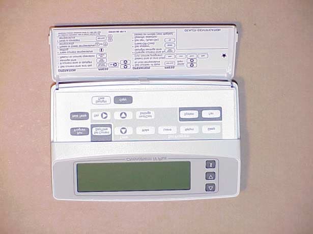
Click to zoom
Application Details
- Equipment Class
- DSC - Part 15 Security/Remote Control Transmitter
- Date of Grant
- Sep 26, 2001
- Application Purpose
- Original Equipment
- Date of Application
- Aug 06, 2001
- Equipment Note
- Security accessory
- Frequency Range
- 345.00000000 - 345.00000000
- Company
- Ademco Inc.
- Country
- United States
Documents & Files
Document Text
Text extracted from the exhibit documents filed with the FCC. Open a document above to read the original.
Users Manual
® U.S. Registered Trademark Copyright © 2001 Honeywell • •All Rights Reserved INSTALLATION INSTRUCTIONS 69- 1535 T8665A Chronotherm ® IV Deluxe Programmable Wireless Thermostat APPLICATION The T8665 Chronotherm® IV Wireless Thermostat provides electronic control of 24 Vac heating and cooling systems. It must be used with a W8665 Receiver Module. Refer to Table 1 for a general description of the thermostat. The T8665A Thermostats are battery- powered. MERCURY NOTICE If this control is replacing a control that contains mercury in a sealed tube, do not place your old control in the trash. Contact your local waste management authority for instructions regarding recycling and the proper disposal of the old thermostat. INSTALLATION Accessory Required (Not Included) Select one of the receiver modules for your application: — W8665A Receiver Module (RM) for single zone applications. — W8665E RF Zone™ Panel for up to three zones. When Installing this Product... 1. Read these instructions carefully. Failure to follow the instructions can damage the product or cause a hazardous condition. 2. Check the ratings given in the instructions and on the product to make sure the product is suitable for your application. 3. Installer must be a trained, experienced service technician. 4. After completing installation, use these instructions to check out the product operation. Location Install the thermostat about 5 ft (1.5m) above the floor in an area with good air circulation at average temperature. See Fig. 1. Do not install the thermostat where it can be affected by: — drafts, or dead spots behind doors and in corners. — hot or cold air from ducts. — radiant heat from sun or appliances. — concealed pipes and chimneys. — unheated (uncooled) areas such as an outside wall behind the thermostat. Wallplate Installation The thermostat can be mounted horizontally on the wall or on a 2 in. x 4 in. wiring box. Position wallplate horizontally on the wall or on a 2 in. x 4 in. wiring box. 1. Position and level the wallplate (for appearance only). The thermostat functions correctly even when not level. 2. Use a pencil to mark the mounting holes. See Fig. 2. 3. Remove the wallplate from the wall and drill two 3/16 in. holes in the wall (if drywall) as marked. For firmer material such as plaster, drill two 7/32 in. holes. 4. Gently tap anchors (provided) into the drilled holes until flush with the wall. 5. Position the wallplate over the holes. 6. Loosely insert the mounting screws into the holes. 7. Tighten the mounting screws. Table 1. T8665A Thermostat Description. T8665SystemChangeoverSystem SelectionFan SelectionComments AHeat-CoolAutomaticHeat-Off-Cool-AutoOn-AutoSystem and fan selections are entered at keyboard. WIRELESS THERMOSTAT 69-15352 Fig. 1. Typical thermostat location. Fig. 2. Mounting the wallplate. Mounting Thermostat 1. Engage tabs at the top of the thermostat and wall- plate. See Fig. 3. 2. Press lower edge of case to close and latch. NOTE: To remove the thermostat from the wall, first pull out at the bottom of the thermostat; remove top last. Fig. 3. Mounting thermostat on wallplate. Using Thermostat Keys The thermostat keys are used to: •set current day and time. •program times and setpoints for heating and cooling. •temporarily override program temperatures •display present setting, •configure Installer Setup, •check self-test, •set the system operation, •set the fan operation. See Fig. 4 for key locations. 5 FEET [1.5 METERS] YES NO NO NO M10106 WIRES THROUGH WALL WALL MOUNTING HOLES M15044 MOUNTING SCREWS WALL ANCHORS (2) M14628 PRESS LOWER EDGE OF CASE TO LATCH. ENGAGE TABS AT TOP OF THERMOSTAT AND WALLPLATE. A. B. WIRELESS THERMOSTAT 369-1535 Fig. 4. T8665A key locations and descriptions. Setting up T8665A to Send Signal to W8665A,E Receiver Module The T8665A Thermostat must be set up to send signals to the W8665 Receiver Module. Use the W8665A Receiver for single-zone applications. Use the W8665E RF Zone™ Panel for up to three T8665A Thermostats for multizone applications. Single Zone Applications (one T8665A/ one W8665A) 1. Place the Zone 1 DIP switch on the W8665A Receiver to the On position. NOTE: Observe that the Zone 1 LED on the W8665 flashes. 2. Press the thermostat Fan key to the On position. The receiver accepts the message, stores identity and then stops flashing the Zone 1 LED. The ther- mostat is now set up to send signals the W8665A Receiver. NOTE: The word On and a fan blade appear in the thermostat display to indicate the thermostat is calling for the fan to turn on. 3. Set the System and Fan keys to the desired loca- tions. NOTE: At any time, if you want to stop the thermostat from sending signals to the W8665 Receiver, simply turn the DIP switch to the Off position. Follow the instructions in steps above to set up the thermostat again to send signals to the W8665A Receiver. Multizone Applications (Up to three T8665A/ one W8665E) IMPORTANT The thermostats must be set up one zone at a time to ensure a unique address is used for each zone. 1. Place the Zone 1 DIP switch on the W8665E Receiver to the On position. NOTE: Observe that the Zone 1 LED on the W8665 flashes. 2. Press the thermostat Fan key to the On position. The Receiver accepts the message, stores the identity of that zone, and stops flashing the Zone 1 LED. The thermostat is now set up to send signals to Zone 1 of the W8665E Receiver. NOTE: The word On and a fan blade appear in the thermostat display to indicate the thermostat is calling for the fan to turn on. 3. Set the System and Fan keys to the desired loca- tions. NOTE: At any time, if you want to stop the thermostat from sending signals to the W8665 Receiver, simply turn the DIP switch to the Off position. Follow the instructions in steps above to set up the thermostat again to send signals to the W8665E Receiver. 4. Repeat steps 1-3 for zones two and three. 5. Attach the zone number stickers, included with the thermostat, onto the thermostat case on the inside o…
Text truncated - open the document above for the full version.
Operational Description
EXHIBIT 1-1 CFS8DL5800STAT Functional Description. The 5800STAT is a battery powered portable transmitter and is part of a wireless control system which complies with 15.231(e). It is used in conjunction with a receiver to control a residential heating, ventilation and air conditioning system. The transmitter does NOT send actual temperature data, it simply sends a control message to the receiver when the temperature reaches a certain internally preset temperature The messages are transmitted at 345Mhz +/-82Khz using on-off keyed AM modulation. The 5800STAT sends a regular supervision "or check-in" message, no more often than once every 7.5 minutes. It also sends control messages initiated by manual override switches on the thermostat and at preset operating set points.
Operational Description
EXHIBIT 3 CFS8DL5800STAT 5800STAT - Duty Cycle Calculation Message protocol, timing and duty cycle calculation. The data output is phase-encoded Manchester that has inherent 50% duty cycle and consists of 64 bits per word A supervision transmission is six identical words separated by (start to start) by nominal 125mSec (100 mSec min, 150 mSec max). Each message has a nominal data rate of 3.7 kb/s (3.2kb/s min to 4.2kb/s max). Therefore the duty cycle is calculation is as follows: The word format consists of 64 bits, The duration of each bit is 312.5 uSec max. The duty cycle over a 100 mSec measuring period is calculated as follows: Duty cycle = Actual RF transmission ON time / 100 mSec Actual transmission ON time = 64 bits X 50% X 312.5 uSec = 10 mSec Therefore duty cycle = 10 / 100 mSec = .10 = 10%, and peak to average field strength is 20 db. Total on-air time for a supervision transmission is: 64 X 312.5 uSec + (5 X 150 mSec) = 0.77 seconds In the case of an alarm transmission, the group of six transmissions is repeated twice, with the second group delayed from the first by a max time of 2 seconds. The worst case on-air time is 2 X (supervision time) + 2 = 3.54 seconds Summary: - Duty cycle = 10% On airtime = 3.54 seconds
Operational Description
EXHIBIT 2-1 CFS8DL5800STAT Operational Description The 5800STAT uses a single chip transmitter which contains a: reference oscillator, a divide by 32 divider, phase detector, and carrier oscillator, these all combine to form a phase locked loop .the carrier oscillator is fed into the PA stage, which is also part of the chip.There are a minimum of external components used. C2 is the bypassing for the chip,.crystal Y1 is the frequency determining element of the reference oscillator ( 10.78125 Mhz. X 32 = 345.00 Mhz. ). C6 and L2 tune the PA, while C11 bypasses the tank circuit. L1 and C14 serve to further reduce harmonics, while C3 couples energy into the printed antenna. the network R1, R3 / C1, shapes the input data. The TX gate and Data come from the standard ADEMCO encoder chip. It should be reiterated, that the 5800STAT only sends COMANDS to run a heating, cooling system, or fan and NOT the actual temperature data itself.
Test Report
EXHIBIT 5-1 CFS8DL5800STAT Report of Measurements. Measurements were made at Ademco 's Measurement Facility at 160 Eileen Way , Syosset , NY 11791 , FCC Registration number : 90421. Measurements were made in accordance with the procedures and reporting requirements of ANSI C63.4-1992. The Test Set-Up (C63.4 section 10.1.3) is shown in the attached drawing. The sequence of testing (C63.4 section 10.1.7) for radiated emissions is as follows: A preliminary scan was conducted with the receiver antenna close to the EUT in order to identify the emission characteristics of the EUT (C63.4 section 8.3.1.1). The antenna and EUT were then placed at the proper separation with the EUT positioned on a non-conducting turntable. The EUT was rotated on the turntable to maximize the received signal strength, then the receiver antenna height was varied to further maximize the received reading. Thereafter, the device was again rotated to a peak output position and the antenna height was re-adjusted for maximum received signal. This procedure was re-iterated until there was no further increase in signal level. This procedure was performed with the EUT rotating in three orthogonal planes (C63.4 section 13.1.4.1) to generate a final maximum reading which is recorded on the radiated emissions result sheet. Similar measurements were made on the receiver to ensure compliance as an unintentional radiator. See Exhibit 6 for list of test equipment (C63.4 section 10.1.4). Note, Spectrum Analyzer resolution bandwidths set as follows; (Video Bandwidth set greater than RBW) - For occupied bandwidth measurements, RBW = 100kHz, (This is in accordance with the minimum RBW allowed by C63.4, which requires RBW greater than 5% of the FCC required occupied bandwidth spec of 0.25% of center frequency). - For radiated emissions below 1 GHz, the RBW = 100kHz. Detector function set to peak. - For radiated emissions above 1 GHz, the RBW = 1MHz. Detector function set to peak. OCCUPIED BANDWIDTH is shown on attached plot. RADIATED EMISSIONS are recorded on attached sheet.
Test Report
Frequency (MHz) Antenna Polarity ( V-H ) Meter Reading (dB uV) Cable/Amp Factor ( dB ) Antenna Factor (dB/M) Converted Reading ( uV/M ) Duty Cycle ( % ) Corrected Reading ( uV/M ) Limit @ 3 Meter ( uV/M ) 30 H 10 291 345 V 72.33 1.7 15.1 28,608.8 10 2,860.9 2,910 690 V 43.0 2.3 20.6 1,972.4 10 197.2 291 1035 H 30.0 3.2 24.0 724.4 10 72.4 291 1380 H 32.0 3.5 27.9 1,479.1 10 147.9 291 1725 V 22.0 3.8 30.0 616.6 10 61.7 291 2070 H 25.0 4.3 28.0 732.8 10 73.3 291 2415 H 22.0 4.5 28.8 582.1 10 58.2 291 2760 H 22.0 4.6 30.0 676.1 10 67.6 291 3105 H 22.0 4.6 30.7 732.8 10 73.3 291 3450 H 22.0 5.1 31.1 812.8 10 81.3 291 4000 H 22.0 10 291 JULY, 10, 2001 GREG BARBATO KEN ADDY DATE:____________________ TESTED BY:_________________________APPROVED BY:________________________ ADEMCO 5800STAT (TRANSMITTER) TEST SAMPLE (model): _______________________________________________________________________________ TEST METHOD: ANSI C63.4-1992 TEST SPECIFICATION: FCC PART 15, SUBPART C. NOTES: 1) Fo= 345 MHZ 2) DETECTOR = PEAK. 3) FREQUENCY RANGE SCANNED TO 4 GHz. (METER READING +CABLE /AMP FACTOR +ANTENNA FACTOR) 20 4) CONVERTED READING = 10 5) CORRECTED READING = CONVERTED READING X DUTY CYCLE 6) SIX HIGHEST EMISSIONS RECORDED. ALARM DEVICE MANUFACTURING COMPANY 165 EILEEN WAY CFS8DL5800STAT SYOSSET, NY 11791 FCC ID#____________________
Test Report
EXHIBIT 6 CFS8DL5800STAT Test Equipment list 1. Antenna: RGA-60 S/N: 6127 Cal. on: 10/19/00 Cal. due: 10/19/01 2. Antenna: Log Periodic S/N:365 Cal. on: 07/28/00 Cal. due: 07/28/01 3. Spectrum Analyzer H. P. 8563E S/N:3246A00232 Cal. on: 03/01/01 Cal. due: 03/01/02
Contact Information
Applicant
Christian Fouth(Sr. Wireless Certification Engineer)
Technical Contact
Alarm Device Manufacturing CompanyKen L Addy
[email protected]516-921-6704
A Division of Pittway Corporation · Syosset, New York · United States
Non-Technical Contact
Alarm Device Manufacturing CompanyKen L Addy
[email protected]516-921-6704
Test Firm
AdemcoKenneth Addy
Technical Specifications
| # | Rule Parts | Frequency Range | Power Output |
|---|---|---|---|
| 1 | 15C | 345 MHz - 345 MHz | - |
Other Applications from Ademco Inc.

CFS8DL5800MINIV
Jan 28, 2026Wireless Alarm Transmitter
Equipment Class
DXX - Part 15 Low Power Communication Device Transmitter
CFS8DLWTS800
Jan 12, 2026Wireless Alarm Transmitter
Equipment Class
DTS - Digital Transmission SystemCFS8DLCAMWEWI1
Jul 25, 2024VX5 HD Indoor Camera
Equipment Class
DTS - Digital Transmission System
CFS8DLCAMWEWO1
Sep 17, 2023VX3 HD Outdoor Camera
Equipment Class
NII - Unlicensed National Information Infrastructure TX
CFS8DLLMD500A
Jul 20, 2023Wireless door/window contact
Equipment Class
DTS - Digital Transmission System